EP0366155B1 - Logarithmic function arithmetic unit including means for separately processing pseudo division and multiplication - Google Patents
Logarithmic function arithmetic unit including means for separately processing pseudo division and multiplication Download PDFInfo
- Publication number
- EP0366155B1 EP0366155B1 EP89120128A EP89120128A EP0366155B1 EP 0366155 B1 EP0366155 B1 EP 0366155B1 EP 89120128 A EP89120128 A EP 89120128A EP 89120128 A EP89120128 A EP 89120128A EP 0366155 B1 EP0366155 B1 EP 0366155B1
- Authority
- EP
- European Patent Office
- Prior art keywords
- value
- adder
- subtracter
- register
- held
- Prior art date
- Legal status (The legal status is an assumption and is not a legal conclusion. Google has not performed a legal analysis and makes no representation as to the accuracy of the status listed.)
- Expired - Lifetime
Links
Images
Classifications
-
- G—PHYSICS
- G06—COMPUTING OR CALCULATING; COUNTING
- G06F—ELECTRIC DIGITAL DATA PROCESSING
- G06F1/00—Details not covered by groups G06F3/00 - G06F13/00 and G06F21/00
- G06F1/02—Digital function generators
- G06F1/03—Digital function generators working, at least partly, by table look-up
- G06F1/0307—Logarithmic or exponential functions
-
- G—PHYSICS
- G06—COMPUTING OR CALCULATING; COUNTING
- G06F—ELECTRIC DIGITAL DATA PROCESSING
- G06F7/00—Methods or arrangements for processing data by operating upon the order or content of the data handled
- G06F7/38—Methods or arrangements for performing computations using exclusively denominational number representation, e.g. using binary, ternary, decimal representation
- G06F7/48—Methods or arrangements for performing computations using exclusively denominational number representation, e.g. using binary, ternary, decimal representation using non-contact-making devices, e.g. tube, solid state device; using unspecified devices
- G06F7/544—Methods or arrangements for performing computations using exclusively denominational number representation, e.g. using binary, ternary, decimal representation using non-contact-making devices, e.g. tube, solid state device; using unspecified devices for evaluating functions by calculation
- G06F7/556—Logarithmic or exponential functions
-
- G—PHYSICS
- G06—COMPUTING OR CALCULATING; COUNTING
- G06F—ELECTRIC DIGITAL DATA PROCESSING
- G06F7/00—Methods or arrangements for processing data by operating upon the order or content of the data handled
- G06F7/38—Methods or arrangements for performing computations using exclusively denominational number representation, e.g. using binary, ternary, decimal representation
- G06F7/48—Methods or arrangements for performing computations using exclusively denominational number representation, e.g. using binary, ternary, decimal representation using non-contact-making devices, e.g. tube, solid state device; using unspecified devices
- G06F7/483—Computations with numbers represented by a non-linear combination of denominational numbers, e.g. rational numbers, logarithmic number system or floating-point numbers
- G06F7/4833—Logarithmic number system
Definitions
- the present invention relates to a scientific computing machine and, in particular, to a logarithmic function arithmetic unit for use in the machine.
- STL Simential Table Lookup
- a known logarithmic function arithmetic unit using the STL method comprises a single barrel shifter and a single adder/subtractor and effects loop processes of the STL method under the microprogram control.
- the arithmetic result is not of high precision since, for example, the number of significant digits is reduced.
- the present invention is defined in claim 1.
- the STL method will be described below for computing a logarithmic function log e (1 + x) with a precision of n digits in the binary system.
- a known logarithmic function arithmetic unit shown therein uses the STL algorithm as described above.
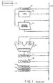
- the arithmetic unit comprises w, x, y, and z registers 11, 12, 13 and 14 for holding w, x k , y k and z k , respectively, an adder/subtracter 15 for effecting addition/subtraction of two inputs A and B, a read-only memory (ROM) 16 for generating r k , a barrel shifter 17 for shifting an input value by desired digits rightwardly, k counter 18 for providing k to read-only memory 16 and a digit number to be shifted at the barrel shifter 17, and a loop number control counter or n counter 19 for controlling the STL loop number.
- Those registers 11-14, adder/subtracter 15, read-only memory 16, barrel shifter 17, and counters 18 and 19 are connected through a data bus 20.
- the unit comprises a micro controller 10 for controlling those blocks 11-19.
- the arithmetic unit executes the STL loop of Process III as follows.
- Equation (9) is obtained.
- Equation (4) since r k of Equation (4) is reduced by increase of k, significant digits are reduced so that rounding errors are accumulated at the least significant bit.
- Equations of (7), (8), (9), (11), (12) and (13) are computed with use of fixed-point numbers, conversion must be made between the fixed-point system and the floating-point system when x and log e (1 + x) are represented by use of the floating-point system. In conversion of x of a small number from the floating-point system to the fixed-point system, the significant digits are considerably reduced. Therefore, the known unit is low in the precision.
- the present invention attempts to use a modified STL method so as to separately perform the pseudo division and the pseudo multiplication by use of hardware such as a single barrel shifter, two adder/subtracters, a stack of a first-in last-out type and a divider without use of the microprogram control.
- Equation (1) ⁇ ⁇ 2 n . Therefore, in order to achieve 2n-digit precision in the binary system according to the modified STL method, the pseudo multiplication is executed by use of approximation log e (1 + ⁇ ) ⁇ ⁇ which is accepted according to the Taylor expansion. Accordingly, the total step number of the pseudo division and the pseudo multiplication is about n which is equal to the step number in the conventional STL method.
- y k is shifted to a lower digit at one step of the pseudo division in order to improve the precision.
- x k is shifted to a higher digit in the pseudo multiplication.
- the arithmetic unit shown therein comprises a first and a second register 41 and 42 for holding two variables Y k and 2X k , a read-only memory 43 for generating a constant ⁇ k given by Equation (24), a barrel shifter 44 for shifting a value of a variable supplied from the second register 42, an exponential circuit 45 for executing Process II and for controlling a digit number to be shifted at the barrel shifter 44 and an address of the read-only memory 43, a first adder/subtracter 46 for effecting addition/subtraction of two inputs A and B so as to execute Equations (17) and (18), a second adder/subtracter 47 for effecting addition/subtraction of two inputs C and D so as to execute Equation (15), a first shifter 48 for shifting an output value from the first adder/subtracter 46 to produce a half value, a second shifter 49 for shifting an output value from the second adder/subtractor 47 to produce a twice value, a stack of
- a sign indication digit of the value in the second register 42 is pushed out and supplied to the stack 50.
- Y k is supplied from the first register 41 to the first adder/subtractor 46 as input A through the data bus 53 and is also supplied to the barrel shifter 44 through the data bus 52.
- the barrel shifter 44 shifts Y k by the digit number indicated by the exponential circuit 45 to produce 2 -k ⁇ Y k which is supplied to the first adder/subtracter 46 as input B.
- Equation (17) is obtained.
- Equation (25) is obtained.
- Each of Operations 4 and 7 is executed by one clock. Therefore, the entire processing time is 2(m - i) clocks which is equal to or smaller than n clocks.
Landscapes
- Engineering & Computer Science (AREA)
- Physics & Mathematics (AREA)
- General Physics & Mathematics (AREA)
- Theoretical Computer Science (AREA)
- General Engineering & Computer Science (AREA)
- Computational Mathematics (AREA)
- Mathematical Analysis (AREA)
- Pure & Applied Mathematics (AREA)
- Computing Systems (AREA)
- Mathematical Optimization (AREA)
- Complex Calculations (AREA)
Description
- The present invention relates to a scientific computing machine and, in particular, to a logarithmic function arithmetic unit for use in the machine.
- As a known logarithmic function arithmetic method, the so called STL (Sequential Table Lookup) method is disclosed in IRE Transactions on Electronic Computers, vol. 11, no. 2, April 1962, pages 155-164; Cantor et al.: "Logarithmic and Exponential Function Evaluation in a Variable Structure Digital Computer". The STL Method is known to be suitable for a computing machine of a microprogram control type, and is efficient, especially, for a computing machine having no high speed multiplier.
- A known logarithmic function arithmetic unit using the STL method comprises a single barrel shifter and a single adder/subtractor and effects loop processes of the STL method under the microprogram control.
- However, the known arithmetic unit suffers from the following problems.
- When it is provided that b (b is an integer) clocks are required for processing one loop process of the STL, (n x b) clocks (n being an integer) are required for processing n loop processes of the STL to compute a logarithmic function. This means that it takes a long time for computing a logarithmic function.
- Further, the arithmetic result is not of high precision since, for example, the number of significant digits is reduced.
- Therefore, it is an object of the present invention to provide a logarithmic function arithmetic unit which has hardware for effecting the STL method to thereby considerably reduce the computing time in comparison with use of the microprogram control.
- It is another object of the present invention to provide a logarithmic function arithmetic unit which can produce a computed result with precision and with an increased number of significant digits.
- The present invention is defined in
claim 1. -
- Fig. 1 is a block diagram view of a known logarithmic function arithmetic unit using the microprogram control;
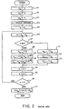
- Fig. 2 is a flow chart for illustrating the arithmetic processes in the known unit of Fig. 1; and
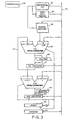
- Fig. 3 is a block circuit diagram view of a logarithmic function arithmetic unit according to an embodiment of the present invention.
- Prior to description of preferred embodiment of the present invention, description is made as to the STL method and a known logarithmic function arithmetic unit using the microprogram control in order to help better understanding of the present invention.
- The STL method will be described below for computing a logarithmic function loge(1 + x) with a precision of n digits in the binary system.
- A given value x is represented by the following equation (1) by use of a sequence of numbers {ak}, as is known in the art:


- Now, the algorithm of the STL method will be described below.
- Process I. x₀ = x (1/2 ≦ x < 1), y₀ = 1, and z₀= 0 are given as initial values.
- Process II. For k = 0, 1, 2, ..., (n - 1), the following process III are repeated.
-


- Process IV. loge(1 + x₀/y₀) = loge(1 + x₀) = Zn is obtained.
- Referring to Fig. 1, a known logarithmic function arithmetic unit shown therein uses the STL algorithm as described above. The arithmetic unit comprises w, x, y, and
z registers barrel shifter 17 for shifting an input value by desired digits rightwardly,k counter 18 for providing k to read-only memory 16 and a digit number to be shifted at thebarrel shifter 17, and a loop number control counter orn counter 19 for controlling the STL loop number. Those registers 11-14, adder/subtracter 15, read-onlymemory 16,barrel shifter 17, andcounters data bus 20. The unit comprises a micro controller 10 for controlling those blocks 11-19. - Now, operation of the arithmetic unit will be described below with reference to Fig. 2.
-
Operation 1. According to Process I, initial values x₀, y₀ and z₀ are set in the x, y andz counters steps number control counter 19 andk counter 18 atsteps 24 and 25 in Fig. 2. -
Operation 2. According to Process II, the following operation 3 is repeated until content of the loopnumber control counter 19 becomes 1. - Operation 3. The arithmetic unit executes the STL loop of Process III as follows.
- Contents xk and yk in x and
y registers data bus 20 under control of the micro controller 10. The adder/subtracter 15 makes (xk - yk) which is supplied to thew register 11. Thew register 11 holds (xk - yk) as w. Thus, Equation (5) is given at astep 26 as shown in Fig. 2. - When w ≧ 0 at a
step 27 in Fig. 2, that is, a sign digit in thew register 11 indicates positive, the following operation is effected under control of the micro controller 10. The content w in thew register 11 is transferred to thex register 12 at astep 28. Thus, Equation (7) is obtained. Then, yk is transferred from y register 13 to the adder/subtracter 15 as the A input and to thebarrel shifter 17. The yk is shifted by the shifted digit number supplied from thek counter 18 to produce yk·2-k which is supplied to the adder/subtracter 15 as the B input. Then, the adder/subtracter 15 makes (A + B) = (yk + yk2-k) which is transferred to the y register 13 at astep 29 shown in Fig. 2. Thus, Equation (8) is obtained. Then, zk in thez register 14 is transferred to the adder/subtracter 15 as the A input, while a constant indicated by thek counter 18, that is, rk is read from the read-only memory 16 and is supplied to the adder/subtracter 15 as the B input. The adder/subtracter 15 makes (A + B) = (zk + rk) which is transferred to thez register 14 at astep 30. Thus, Equation (9) is obtained. - When w < 0, that is, a sign digit in the
w register 11 indicates negative atstep 27, the arithmetic unit does nothing as shown atsteps - After a loop of
steps 26 to 30 or 33 is completed, the content ofk counter 18 is increased by one (1) atstep 34 and the content of loopnumber control counter 19 is reduced by one (1) atstep 35 as shown in Fig. 2. The loop is repeated until the content of loopnumber control counter 19 becomes 0. - Operation 4. When the content of loop
number control counter 19 is 0 at thestep 36, the operation 3 is completed. Then, the content of thez register 14 provides an arithmetic result of loge (1 + x₀) as shown atstep 37 in Fig. 2. - In the known arithmetic unit, the above-described operation is executed under the microprogram control. Providing that b clocks are required for processing the STL loop in operation 3 one time, (n x b) clocks are required for obtaining the arithmetic result. Therefore, it takes a long time to compute the logarithmic function.
- Further, since rk of Equation (4) is reduced by increase of k, significant digits are reduced so that rounding errors are accumulated at the least significant bit. Moreover, since Equations of (7), (8), (9), (11), (12) and (13) are computed with use of fixed-point numbers, conversion must be made between the fixed-point system and the floating-point system when x and loge(1 + x) are represented by use of the floating-point system. In conversion of x of a small number from the floating-point system to the fixed-point system, the significant digits are considerably reduced. Therefore, the known unit is low in the precision.
- In order to resolve those problems of the known arithmetic unit using the STL method under the microprogram control, the present invention attempts to use a modified STL method so as to separately perform the pseudo division and the pseudo multiplication by use of hardware such as a single barrel shifter, two adder/subtracters, a stack of a first-in last-out type and a divider without use of the microprogram control.
- Although the pseudo division and the pseudo multiplication are executed simultaneously or corelatively in the conventional STL method, the former is at first executed and then the latter is done in the modified STL method.
- In the conventional STL method, ε (pseudo remainder) in Equation (1) is ignored and the pseudo multiplication is executed using y₀ = 1 as the initial value. Therefore, n-times of the STL loop are required for achieving a n-digit precision in the binary system.
- In Equation (1), ε < 2n. Therefore, in order to achieve 2n-digit precision in the binary system according to the modified STL method, the pseudo multiplication is executed by use of approximation loge(1 + ε) ≒ ε which is accepted according to the Taylor expansion. Accordingly, the total step number of the pseudo division and the pseudo multiplication is about n which is equal to the step number in the conventional STL method.
- In the modified STL method, yk is shifted to a lower digit at one step of the pseudo division in order to improve the precision. On the contrary, xk is shifted to a higher digit in the pseudo multiplication.
- Further, using Xm = Xm/Ym as the initial value where Xm is a remainder of a pseudo division and


- Since x and y are floating-point numbers and since loge(1 + x/y) ≒ x/y for x/y<<1, the pseudo division is stated from an intermediate step while the pseudo multiplication is stopped at an intermediate step. As a result, it is prevented that the significant digits are reduced due to digit matching and, moreover performance is improved.
- Now, description is made as to the algorithm of the modified STL for computing loge(1 + x/y) with n (= 2m) digit precision.
- Process I. x and y are inputted (0 ≦ x < y < +∞).
- Process II. X, Y, i and j are determined for satisfying x = 2-i X (1 ≦ X < 2, i being an integer) and y = 2-j·Y (1 ≦ Y < 2, j being an integer), X and Y are mantissa portions of x and y, respectively, while i and j are exponential portions of x and y, respectively. Values xi = X, yj = Y and i = (j - i) are selected as initial values.
- Process III. For k = i, (i + 1), (i + 2), ..., (m - 1), the following process IV is repeated, that is, pseudo division is executed. Herein, m is an integer larger than (i+1).
- Process IV. The following equation (15) is given:

- When W ≧ 0, the following equations (16) to (18) are obtained:


- When W< 0, the following equations (19) to (21) are obtained:


- Process V. Ym given by the following equation (22) is selected as an initial level for the pseudo multiplication:

- Process VI. For k = m, (m - 1), (m - 2), ..., (i + 1), the following process VII is repeated, that is, the pseudo multiplication is executed.
- Process VII. For ak = +1,


- Process VIII. loge(1 + x/y) = Xi is obtained.
- The algorithm of modified STL method described above is disclosed, as pseudo division and pseudo multiplication processes, in IBM Journal, April 1962, pages 210-226; Meggitt: "Pseudo Division and Pseudo Multiplication Processes". In the IBM journal, the arithmetic is performed with not binary base 10. There is none of units implemented for performing the algorithm.
- Now, a logarithmic function arithmetic unit using the above algorithm of the modified STL method will be described with reference to Fig. 3.
- Referring to Fig. 3, the arithmetic unit shown therein comprises a first and a second register 41 and 42 for holding two variables Yk and 2Xk, a read-only memory 43 for generating a constant Γk given by Equation (24), a barrel shifter 44 for shifting a value of a variable supplied from the second register 42, an exponential circuit 45 for executing Process II and for controlling a digit number to be shifted at the barrel shifter 44 and an address of the read-only memory 43, a first adder/subtracter 46 for effecting addition/subtraction of two inputs A and B so as to execute Equations (17) and (18), a second adder/subtracter 47 for effecting addition/subtraction of two inputs C and D so as to execute Equation (15), a first shifter 48 for shifting an output value from the first adder/subtracter 46 to produce a half value, a second shifter 49 for shifting an output value from the second adder/subtractor 47 to produce a twice value, a stack of a first-in last-out type 50 for holding an inversion of a sign indication bit of a value in the second register 42 so as to control the addition, subtraction or transferring in the first and the second adder/subtractors 46 and 47, and a divider 51 for executing Process V, which are connected to one another through a data bus 52. An output of the
first register 41 is connected to the first and the second adder/subtractors data bus 53. The unit further comprises acontroller 54 for controlling the blocks 41-51. - Now, description will be made as to the operation of the arithmetic unit of Fig. 3 below, according to the Algorithm of the modified STL method.
-
Operation 1. According to Process I, binary floating-point numbers x and y are supplied onto thebus 52. Where 0 ≦ x < y < + ∞ . -
Operation 2. Theexponential circuit 45 receives the numbers x and y and executes Process II to obtain the mantissa portions X and Y and the index portions i and j and j = (i - j). Y and 2·X are transferred under control of thecontroller 54 to the first and the second registers 41 and 42, respectively, through thebus 52. - Operation 3. According to Process III, the following operation 4 is repeated with k being incremented by 1 from k = i to k =(m - 1), that is, the pseudo division is executed. The incrementation is performed by the
exponential circuit 45. - Operation 4. At first, Yk is supplied from the
first register 41 to the second adder/subtractor 47 as an input C through thedata bus 53, while 2Xk is supplied from thesecond register 42 to the second adder/subtractor 47 as another input D. The adder/subtractor 47 subtracts the input C from the input D to produce W = 2Xk - Yk which is shifted by theshifter 49 and written as 2Xk+1 = 2W into thesecond register 42. Thus, Equation (15) is completed. - Then, a sign indication digit of the value in the
second register 42 is pushed out and supplied to thestack 50. Yk is supplied from thefirst register 41 to the first adder/subtractor 46 as input A through thedata bus 53 and is also supplied to thebarrel shifter 44 through thedata bus 52. Thebarrel shifter 44 shifts Yk by the digit number indicated by theexponential circuit 45 to produce 2-k·Yk which is supplied to the first adder/subtracter 46 as input B. When the sign indication bit indicates positive in thesecond register 42, that is, ak = +1, the first adder/subtractor 46 makes (A + B) = (Yk + 2-k·Yk) which is supplied to thefirst register 41. As a result, Equation (17) is obtained. - On the other hand, when the sign indication bit is negative, the second adder/
subtractor 47 makes (0 + D) = 2Xk which is shifted at thesecond shifter 49 to produce a twice value of 2·2·Xk. Thevalue 2·2·Xk is held in thesecond register 42. Thus, Equation (21) is obtained. - Operation 5. According to Process V, the
divider 51 divides Xm held in thesecond register 42 by Ym held in thefirst register 41 to form Xm = Xm/Ym which is supplied to thefirst register 41 as an initial value for the pseudo multiplication. - Operation 6. According to Process VI, the following operation 7 is repeated with k being decremented by 1 from k = m to k =(i + 1), that is, the pseudo multiplication is executed. The decrementation is also performed by the
exponential circuit 45. - Operation 7. Xk is supplied from the
first register 41 to the first adder/subtractor 46 as input A through thedata bus 53. Simultaneously, Γk is supplied from the read-only memory 43 to the first adder/subtractor 46 as input B. At that time, when a positive number is popped from thestack 50, that is ak = +1, the first adder/subtractor 46 makes (A + B) = (Xk + Γk) which is shifted at thefirst shifter 48 to produce (Xk + Γk)/2. Then, (Xk + Γk)/2 is held as Xk+1 in thefirst register 41. Thus, Equation (23) is obtained. On the other hand, a negative number is popped from thestack 50, that is ak = 0, the first adder/subtractor 46 makes (A+0) to produce Xk. The Xk is shifted by thefirst shifter 48 to produce Xk/2 which is held as Xk+1 in thefirst register 41. Thus, Equation (25) is obtained. - Operation 8. As a result, the content X in the
first register 41 provides a mantissa portion of loge(1 + x/y). - Each of Operations 4 and 7 is executed by one clock. Therefore, the entire processing time is 2(m - i) clocks which is equal to or smaller than n clocks.
- The operation has been described in connection with use of floating-point numbers but the arithmetic unit of the present invention can use fixed-point numbers by fixing the index portion i to be 0.
Claims (3)
- A logarithmic function arithmetic unit for computing a function of loge (1 + x/y) by use of the algorithm of pseudo division and pseudo multiplication processes, which comprises:means (45) responsive to input numbers x and y with 0≤x<y< +∞, for computing mantissa portions X and Y, with 1≤X<2, 1≤Y<2 and exponential portions i and j, i and j being integers, of x and y respectively, to satisfy x=2-i ·X and y = 2-j ·Y, said computing means producing constants of k=0, 1, ..., i, i + 1, i + 2, ..., m-1 and m, m being an integer greater than i + 1;coefficient producing means (43) coupled with said computing means (45) for producing a coefficient of Γk =2k log(1 + 2-k) for k = m-1 to k=0;first register means (41) for holding a first held value, said first register means (41) coupled to said computing means (45) and initially holding Yk = Yi = Y as said first held value;second register means (42) for holding a second held value, said second register means (42) coupled to said computing means (45) and initially holding 2Xk = 2Xi = 2X as said second held value;barrel shifter means (44) coupled to said computing means (45) and said first register means (41) for shifting said first held value by k digits to produce a shifted value 2-k ·Yk;first adder/subtracter means (46) having a first primary input means (A) coupled to said first register means (41) and a first secondary input means (B), said first primary input means (A) receiving said first held value as a first primary input value, said first secondary input means (B) receiving a first secondary input value, said first adder/subtracter means (46) adding said first primary and secondary input values to produce a first sum;second adder/subtracter means (47) having a second primary input means (C) and a second secondary input means (D) coupled to said second register means, said second primary input means (C) receiving a second primary input value, said second secondary input means (D) receiving said second held value as a second secondary input value, said second adder/subtracter means (47) adding or subtracting said second primary input value to or from said second secondary input value to produce a second sum;control means (54) controlling said first and second adder/subtracter means (46, 47), and said barrel shifter means (44) for producing the following operations for k=i, i + 1, i+2, ..., m-1, m;said second adder/subtracter means (47) receiving said first held value as said second primary input value and subtracting said second primary input value from said second secondary input value to produce W = 2Xk-Yk as said second sum;said second register means (42) holding W = 2Xk-Yk as said second held value;first-in last-out stack means (50) coupled to said second register means (42) for stacking a sign indicating value, said sign indicating value being "1" when said second held value is positive or zero, said sign indicating value being "0" when said second held value is negative;said control means (54) controlling said first adder/subtracter means (46) to make the following operations for k = m, m-1, m-2, ..., i+1;said first adder/subtracter means (46) receiving said shifted value 2-k ·Yk as said first secondary input value when said second held value is positive or zero, said first adder/subtracter means (46) producing Yk+1 = Yk+2-k ·Yk as said first sum, said first sum being delivered to said first register means (41), said first register means (41) eventually holding Ym as said first held value; andsaid second adder/subtracter means (47) being set "0" as said second primary input value when said second held value is negative, said second adder/subtracter means (47) producing Xk+1 = 2Xk as said second sum;twice means (49) coupled to said second adder/subtracter means (47) for producing a value twice that of said second sum, said twice value being delivered to said second register means (42), so that said second register means (42) eventually holds 2Xm as said second held value;divider means (51) coupled to said first and second register means (41, 42) for dividing unter control of said control means (54) a half of said second held value 2Xm by said first held value Ym to produce a divided result of Xm=Xm/Ym, said divided result Xm being delivered as Xk to said first register means (41) as said first held value;said first adder/subtracter means (46) receiving, under control of said control means (54), said coefficient Γk as said first secondary input value when said sign indication value "1" is popped from said first-in last-out stack means (50), said first adder/subtracter means (46) producing Xk+Γk as said first sum, said first adder/subtracter means (46) being set "0" as said first secondary input value when said sign indication value "0" is popped from said first-in last-out stack means (50), said first adder/subtracter means (46) producing Xk as said first sum; andshifter means (48) coupled to said first adder/subtracter means (46) for shifting said first sum under control of said control means (54) to produce Xk+1 = (Xk+Γk)/2 alternatively Xk+1 = Xk/2 as a shifted value, said shifted value being delivered to said first register means (41) and being held as said first held value, said first held value finally representing a mantissa Xi of said loge (1 + x/y).
- A logarithmic function arithmetic unit as claimed in claim 1, wherein i is maintained 0, so that the arithmetic is executed by the use of fixed-point system.
- A logarithmic function arithmetic unit as claimed in claim 1, wherein said coefficient producing means (43) comprises a read only memory.
Applications Claiming Priority (2)
| Application Number | Priority Date | Filing Date | Title |
|---|---|---|---|
| JP271013/88 | 1988-10-28 | ||
| JP63271013A JP2822399B2 (en) | 1988-10-28 | 1988-10-28 | Logarithmic function arithmetic unit |
Publications (3)
| Publication Number | Publication Date |
|---|---|
| EP0366155A2 EP0366155A2 (en) | 1990-05-02 |
| EP0366155A3 EP0366155A3 (en) | 1991-11-13 |
| EP0366155B1 true EP0366155B1 (en) | 1996-05-29 |
Family
ID=17494194
Family Applications (1)
| Application Number | Title | Priority Date | Filing Date |
|---|---|---|---|
| EP89120128A Expired - Lifetime EP0366155B1 (en) | 1988-10-28 | 1989-10-30 | Logarithmic function arithmetic unit including means for separately processing pseudo division and multiplication |
Country Status (4)
| Country | Link |
|---|---|
| US (1) | US5041999A (en) |
| EP (1) | EP0366155B1 (en) |
| JP (1) | JP2822399B2 (en) |
| DE (1) | DE68926563T2 (en) |
Families Citing this family (11)
| Publication number | Priority date | Publication date | Assignee | Title |
|---|---|---|---|---|
| EP0554035B1 (en) * | 1992-01-27 | 2001-10-17 | Mitsubishi Denki Kabushiki Kaisha | Solid state color video camera |
| US6788342B1 (en) | 1992-01-27 | 2004-09-07 | Mitsubishi Denki Kabushiki Kaisha | Color video camera for generating a luminance signal with unattenuated harmonics |
| US6055553A (en) * | 1997-02-25 | 2000-04-25 | Kantabutra; Vitit | Apparatus for computing exponential and trigonometric functions |
| US6567832B1 (en) * | 1999-03-15 | 2003-05-20 | Matsushita Electric Industrial Co., Ltd. | Device, method, and storage medium for exponentiation and elliptic curve exponentiation |
| US6976043B2 (en) * | 2001-07-30 | 2005-12-13 | Ati Technologies Inc. | Technique for approximating functions based on lagrange polynomials |
| US7509363B2 (en) * | 2001-07-30 | 2009-03-24 | Ati Technologies Ulc | Method and system for approximating sine and cosine functions |
| US7606850B2 (en) * | 2005-03-30 | 2009-10-20 | Lockheed Martin Corporation | Method and apparatus for providing a base-2 logarithm approximation to a binary number |
| JP4895544B2 (en) * | 2005-07-15 | 2012-03-14 | 株式会社Shoei | Full-face helmet |
| US8510360B2 (en) * | 2010-06-04 | 2013-08-13 | International Business Machines Corporation | Calculating large precision common logarithms |
| US10838718B2 (en) * | 2017-09-28 | 2020-11-17 | Fujitsu Limited | Processing device, arithmetic unit, and control method of processing device |
| WO2020090025A1 (en) * | 2018-10-31 | 2020-05-07 | 富士通株式会社 | Arithmetic processing unit and control method of arithmetic processing unit |
Family Cites Families (2)
| Publication number | Priority date | Publication date | Assignee | Title |
|---|---|---|---|---|
| US4089060A (en) * | 1976-10-15 | 1978-05-09 | Mitchell Donald K | Digital logarithmic apparatus |
| JPS6051733B2 (en) * | 1977-11-19 | 1985-11-15 | 日本電気株式会社 | Exponential function calculation device |
-
1988
- 1988-10-28 JP JP63271013A patent/JP2822399B2/en not_active Expired - Fee Related
-
1989
- 1989-10-30 DE DE68926563T patent/DE68926563T2/en not_active Expired - Fee Related
- 1989-10-30 EP EP89120128A patent/EP0366155B1/en not_active Expired - Lifetime
- 1989-10-30 US US07/428,301 patent/US5041999A/en not_active Expired - Lifetime
Also Published As
| Publication number | Publication date |
|---|---|
| JPH02118725A (en) | 1990-05-07 |
| DE68926563T2 (en) | 1997-01-23 |
| EP0366155A3 (en) | 1991-11-13 |
| JP2822399B2 (en) | 1998-11-11 |
| DE68926563D1 (en) | 1996-07-04 |
| EP0366155A2 (en) | 1990-05-02 |
| US5041999A (en) | 1991-08-20 |
Similar Documents
| Publication | Publication Date | Title |
|---|---|---|
| EP0421092B1 (en) | Method and apparatus for performing mathematical functions using polynomial approximation and a rectangular aspect ratio multiplier | |
| US5046038A (en) | Method and apparatus for performing division using a rectangular aspect ratio multiplier | |
| US5065352A (en) | Divide apparatus employing multiplier with overlapped partial quotients | |
| US4707798A (en) | Method and apparatus for division using interpolation approximation | |
| EP0158530A2 (en) | Nonrestoring divider | |
| EP0381161A2 (en) | Modular multipication method and the system | |
| EP0356153B1 (en) | Radix-2**n divider method and apparatus using overlapped quotient bit selection and concurrent quotient rounding and correction | |
| US5659495A (en) | Numeric processor including a multiply-add circuit for computing a succession of product sums using redundant values without conversion to nonredundant format | |
| EP0472139A2 (en) | A floating-point processor | |
| US5132925A (en) | Radix-16 divider using overlapped quotient bit selection and concurrent quotient rounding and correction | |
| US5258944A (en) | High performance mantissa divider | |
| JPH0235348B2 (en) | ||
| EP0366155B1 (en) | Logarithmic function arithmetic unit including means for separately processing pseudo division and multiplication | |
| EP0297588B1 (en) | Trigonometric function arithmetic processor using pseudo-division | |
| US5144576A (en) | Signed digit multiplier | |
| US5007009A (en) | Non-recovery parallel divider circuit | |
| US4594680A (en) | Apparatus for performing quadratic convergence division in a large data processing system | |
| US5181184A (en) | Apparatus for multiplying real-time 2's complement code in a digital signal processing system and a method for the same | |
| EP0398568A2 (en) | Multiplier circuit | |
| US4949295A (en) | Transformation of divisor and dividend in digital division | |
| US5278782A (en) | Square root operation device | |
| JP2508784B2 (en) | Exponential function calculator | |
| US5825681A (en) | Divider/multiplier circuit having high precision mode | |
| US6598065B1 (en) | Method for achieving correctly rounded quotients in algorithms based on fused multiply-accumulate without requiring the intermediate calculation of a correctly rounded reciprocal | |
| US4716538A (en) | Multiply/divide circuit for encoder PCM samples |
Legal Events
| Date | Code | Title | Description |
|---|---|---|---|
| PUAI | Public reference made under article 153(3) epc to a published international application that has entered the european phase |
Free format text: ORIGINAL CODE: 0009012 |
|
| 17P | Request for examination filed |
Effective date: 19891117 |
|
| AK | Designated contracting states |
Kind code of ref document: A2 Designated state(s): DE FR GB |
|
| PUAL | Search report despatched |
Free format text: ORIGINAL CODE: 0009013 |
|
| AK | Designated contracting states |
Kind code of ref document: A3 Designated state(s): DE FR GB |
|
| 17Q | First examination report despatched |
Effective date: 19940830 |
|
| GRAH | Despatch of communication of intention to grant a patent |
Free format text: ORIGINAL CODE: EPIDOS IGRA |
|
| GRAH | Despatch of communication of intention to grant a patent |
Free format text: ORIGINAL CODE: EPIDOS IGRA |
|
| GRAA | (expected) grant |
Free format text: ORIGINAL CODE: 0009210 |
|
| AK | Designated contracting states |
Kind code of ref document: B1 Designated state(s): DE FR GB |
|
| REF | Corresponds to: |
Ref document number: 68926563 Country of ref document: DE Date of ref document: 19960704 |
|
| ET | Fr: translation filed | ||
| PLBE | No opposition filed within time limit |
Free format text: ORIGINAL CODE: 0009261 |
|
| STAA | Information on the status of an ep patent application or granted ep patent |
Free format text: STATUS: NO OPPOSITION FILED WITHIN TIME LIMIT |
|
| 26N | No opposition filed | ||
| REG | Reference to a national code |
Ref country code: GB Ref legal event code: IF02 |
|
| REG | Reference to a national code |
Ref country code: GB Ref legal event code: 732E |
|
| REG | Reference to a national code |
Ref country code: FR Ref legal event code: TP |
|
| PGFP | Annual fee paid to national office [announced via postgrant information from national office to epo] |
Ref country code: FR Payment date: 20041008 Year of fee payment: 16 |
|
| PGFP | Annual fee paid to national office [announced via postgrant information from national office to epo] |
Ref country code: GB Payment date: 20041027 Year of fee payment: 16 |
|
| PGFP | Annual fee paid to national office [announced via postgrant information from national office to epo] |
Ref country code: DE Payment date: 20041028 Year of fee payment: 16 |
|
| PG25 | Lapsed in a contracting state [announced via postgrant information from national office to epo] |
Ref country code: GB Free format text: LAPSE BECAUSE OF NON-PAYMENT OF DUE FEES Effective date: 20051030 |
|
| PG25 | Lapsed in a contracting state [announced via postgrant information from national office to epo] |
Ref country code: DE Free format text: LAPSE BECAUSE OF NON-PAYMENT OF DUE FEES Effective date: 20060503 |
|
| GBPC | Gb: european patent ceased through non-payment of renewal fee |
Effective date: 20051030 |
|
| PG25 | Lapsed in a contracting state [announced via postgrant information from national office to epo] |
Ref country code: FR Free format text: LAPSE BECAUSE OF NON-PAYMENT OF DUE FEES Effective date: 20060630 |
|
| REG | Reference to a national code |
Ref country code: FR Ref legal event code: ST Effective date: 20060630 |