EP0365904A1 - Safety locking device - Google Patents
Safety locking device Download PDFInfo
- Publication number
- EP0365904A1 EP0365904A1 EP89118705A EP89118705A EP0365904A1 EP 0365904 A1 EP0365904 A1 EP 0365904A1 EP 89118705 A EP89118705 A EP 89118705A EP 89118705 A EP89118705 A EP 89118705A EP 0365904 A1 EP0365904 A1 EP 0365904A1
- Authority
- EP
- European Patent Office
- Prior art keywords
- cover
- base
- hatch
- flap
- plug
- Prior art date
- Legal status (The legal status is an assumption and is not a legal conclusion. Google has not performed a legal analysis and makes no representation as to the accuracy of the status listed.)
- Granted
Links
Images

Classifications
-
- F—MECHANICAL ENGINEERING; LIGHTING; HEATING; WEAPONS; BLASTING
- F16—ENGINEERING ELEMENTS AND UNITS; GENERAL MEASURES FOR PRODUCING AND MAINTAINING EFFECTIVE FUNCTIONING OF MACHINES OR INSTALLATIONS; THERMAL INSULATION IN GENERAL
- F16P—SAFETY DEVICES IN GENERAL; SAFETY DEVICES FOR PRESSES
- F16P3/00—Safety devices acting in conjunction with the control or operation of a machine; Control arrangements requiring the simultaneous use of two or more parts of the body
- F16P3/08—Safety devices acting in conjunction with the control or operation of a machine; Control arrangements requiring the simultaneous use of two or more parts of the body in connection with the locking of doors, covers, guards, or like members giving access to moving machine parts
-
- H—ELECTRICITY
- H04—ELECTRIC COMMUNICATION TECHNIQUE
- H04M—TELEPHONIC COMMUNICATION
- H04M1/00—Substation equipment, e.g. for use by subscribers
- H04M1/02—Constructional features of telephone sets
-
- H—ELECTRICITY
- H04—ELECTRIC COMMUNICATION TECHNIQUE
- H04M—TELEPHONIC COMMUNICATION
- H04M1/00—Substation equipment, e.g. for use by subscribers
- H04M1/64—Automatic arrangements for answering calls; Automatic arrangements for recording messages for absent subscribers; Arrangements for recording conversations
-
- H—ELECTRICITY
- H05—ELECTRIC TECHNIQUES NOT OTHERWISE PROVIDED FOR
- H05K—PRINTED CIRCUITS; CASINGS OR CONSTRUCTIONAL DETAILS OF ELECTRIC APPARATUS; MANUFACTURE OF ASSEMBLAGES OF ELECTRICAL COMPONENTS
- H05K5/00—Casings, cabinets or drawers for electric apparatus
- H05K5/02—Details
- H05K5/0208—Interlock mechanisms; Means for avoiding unauthorised use or function, e.g. tamperproof
-
- Y—GENERAL TAGGING OF NEW TECHNOLOGICAL DEVELOPMENTS; GENERAL TAGGING OF CROSS-SECTIONAL TECHNOLOGIES SPANNING OVER SEVERAL SECTIONS OF THE IPC; TECHNICAL SUBJECTS COVERED BY FORMER USPC CROSS-REFERENCE ART COLLECTIONS [XRACs] AND DIGESTS
- Y10—TECHNICAL SUBJECTS COVERED BY FORMER USPC
- Y10S—TECHNICAL SUBJECTS COVERED BY FORMER USPC CROSS-REFERENCE ART COLLECTIONS [XRACs] AND DIGESTS
- Y10S439/00—Electrical connectors
- Y10S439/911—Safety, e.g. electrical disconnection required before opening housing
Landscapes
- Engineering & Computer Science (AREA)
- General Engineering & Computer Science (AREA)
- Signal Processing (AREA)
- Mechanical Engineering (AREA)
- Computer Security & Cryptography (AREA)
- Microelectronics & Electronic Packaging (AREA)
- Telephone Set Structure (AREA)
- Centrifugal Separators (AREA)
- Medical Preparation Storing Or Oral Administration Devices (AREA)
- Helmets And Other Head Coverings (AREA)
- Connector Housings Or Holding Contact Members (AREA)
- Control Of Vending Devices And Auxiliary Devices For Vending Devices (AREA)
Abstract
Description
La présente invention concerne la sécurité électrique des appareillages téléphoniques.The present invention relates to the electrical safety of telephone equipment.
Les normes de sécurité imposent qu'aucune partie d'un appareillage téléphonique accessible à la main, sans l'utilisation d'outil, ne soit susceptible d'être portée à un potentiel électrique dangereux pour l'usager. Dans les postes téléphoniques simples, cette condition est respectée en enfermant les parties métalliques réputées dangereuses dans des boîtiers isolants qui ne peuvent être ouverts sans outil, grâce à l'utilisation de vis ou tétons de blocage nécessitant un tournevis pour leur déblocage. Pour certains appareillages téléphoniques ayant des boîtiers avec des trappes, par exemple de logement de pile ou de cassette de bande magnétique dans le cas de répondeur téléphonique, on utilise des couvercles de trappe bloqués par des verrous sans tête de préhension manoeuvrables uniquement à l'aide de tournevis ou d'une pointe d'outil. Cela est cependant malcommode pour un usager qui n'a pas toujours un outil à portée de la main lorsqu'il doit changer une pile ou une cassette de bande magnetique.Safety standards require that no part of a telephone apparatus accessible by hand, without the use of a tool, is likely to be brought to an electrical potential dangerous for the user. In simple telephone sets, this condition is met by enclosing the metal parts deemed dangerous in insulating boxes which cannot be opened without tools, thanks to the use of locking screws or nipples requiring a screwdriver to unlock them. For some telephone equipment having housings with hatches, for example battery compartment or magnetic tape cassette in the case of telephone answering machine, use is made of hatch covers blocked by latches without gripping head which can be operated only using screwdriver or tool tip. This is however inconvenient for a user who does not always have a tool at hand when he has to change a battery or a tape cassette.
La présente invention a pour but d'assurer la sécurité électrique d'un appareillage téléphonique ayant un boîtier avec trappe pour le logement d'un composant amovible tout en préservant la commodité de manipulation cela, en obligeant l'usager à déconnecter l'appareillage téléphonique avant et pendant l'ouverture de la trappe.The present invention aims to ensure the electrical safety of a telephone device having a housing with hatch for housing a removable component while preserving the convenience of handling this, by forcing the user to disconnect the telephone device before and during the opening of the hatch.
Elle a pour objet un dispositif de verrouillage de sécurité pour un couvercle de trappe d'un socle d'appareillage téléphonique raccordé à une ligne téléphonique par un connecteur à deux parties embrochables constituées d'une embase fixée dans le socle et d'une fiche fixée à l'extrémité d'un cordon de raccordement. Ce dispositif de verrouillage comporte des moyens de contrôle d'accès pour empêcher l'accès de la fiche à l'embase lorsque le couvercle est ouvert, pour obliger à déconnecter le cordon de raccordement du socle avant de pouvoir ouvrir le couvercle de la trappe, et pour n'autoriser l'accès de la fiche à l'embase et ne permettre son embrochage pour le raccordement du cordon que lorsque le couvercle de la trappe est fermé.It relates to a safety locking device for a hatch cover of a base of telephone equipment connected to a telephone line by a connector with two plug-in parts consisting of a base fixed in the base and a fixed plug. at the end of a connection cord. This locking device includes access control means to prevent access of the plug to the base when the cover is open, to force the connection cord to be disconnected from the base before the cover can be opened, and to allow access from the plug to the base and allow it to be plugged in for cord connection only when the hatch cover is closed.
Avantageusement, les moyens de contrôle d'accès sont constitués d'un volet qui coulisse dans le socle de l'appareillage téléphonique devant l'embase du connecteur entre une position de fermeture au cours de laquelle il dégage l'accès de l'embase à la fiche du connecteur et maintient le couvercle de la trappe fermé, et une position d'ouverture au cours de laquelle il obstrue l'accès de l'embase à la fiche du connecteur et autorise l'ouverture du couvercle de la trappe. Ce volet peut être constitué d'une pièce distincte du couvercle de trappe ou faire partie de celui-ci.Advantageously, the access control means consist of a flap which slides in the base of the telephone equipment in front of the connector base between a closed position during which it clears access from the base to the connector plug and keeps the hatch cover closed, and an open position during which it obstructs access from the base to the connector plug and allows the hatch cover to open. This flap may consist of a separate part of the hatch cover or be part of it.
D'autres caractéristiques et avantages de l'invention ressortiront de la description ci-après de deux modes de réalisation donnés à titre d'exemple. Cette description sera faite en regard du dessin dans lequel :
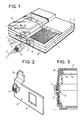
- - une figure 1 montre une vue en perspective d'un socle de répondeur téléphonique avec un couvercle de trappe de logement de cassette de bande magnétique coulissant et un connecteur de raccordement de ligne téléphonique débrochable dans l'axe de coulissement du couvercle,
- - une figure 2 montre une vue en perspective d'un volet d'obturation utilisé dans le socle de répondeur téléphonique représenté à la figure 1 pour condamner l'accès à l'embase du connecteur de raccordement de ligne pendant l'ouverture du couvercle de trappe de logement de cassette de bande magnétique,
- - une figure 3 est une vue en coupe verticale partielle selon la ligne III de la figure 1 et
- - des figures 4 et 5 montrent en perspective un autre socle de répondeur téléphonique ayant un couvercle de trappe de logement de cassette de bande magnétique coulissant et un connecteur de raccordement de ligne téléphonique débrochable dans une direction perpendiculaire de l'axe de coulissement du couvercle, l'une des figures correspondant à une position fermée et l'autre à une position ouverte.
- FIG. 1 shows a perspective view of a telephone answering machine base with a sliding magnetic tape cassette cover flap cover and a withdrawable telephone line connection connector in the sliding axis of the cover,
- - Figure 2 shows a perspective view of a shutter used in the telephone answering machine base shown in Figure 1 to prevent access to the base of the line connection connector during the opening of the cover. magnetic tape cassette housing hatch,
- - Figure 3 is a partial vertical sectional view along line III of Figure 1 and
- FIGS. 4 and 5 show in perspective another telephone answering machine base having a sliding magnetic tape cassette housing cover and a withdrawable telephone line connection connector in a direction perpendicular to the sliding axis of the cover, one of the figures corresponding to a closed position and the other to an open position.
Le socle de répondeur téléphonique représenté à la figure 1 a une forme rectangulaire plate. Formé de deux demi-coquilles 1, 2 en matière plastique moulée il présente sur le dessus, côté droit, un mécanisme de lecteur enregistreur de cassette de bande magnétique recouvert par un couvercle 3 en surépaisseur et, côté gauche, une grille 4 cache haut-parleur. Une ouverture 5 dans la paroi latérale du socle donne accès à l'embase d'un connecteur débrochable dont la fiche 6 est fixée à l'extrémité d'un cordon 7 de raccordement à une ligne téléphonique.The telephone answering machine base shown in Figure 1 has a flat rectangular shape. Made up of two half-
Le couvercle 3 représenté en position de fermeture coulisse selon l'axe F à la manière d'un tiroir grâce à un système de glissières non représenté. Il est prisonnier du socle et s'arrête en bout de course d'ouverture dans une position de butée dès que la cassette de bande magnétique devient accessible.The cover 3 shown in the closed position slides along the axis F in the manner of a drawer thanks to a system of slides not shown. It is trapped in the base and stops at the end of the opening stroke in a stop position as soon as the magnetic tape cassette becomes accessible.
Le mouvement d'ouverture du couvercle 3 est contrôlé à l'aide d'un volet 8 visible en transparence à travers la paroi latérale 15 qui est présentée à l'avant du socle sur la figure 1 et qui correspond à la face arrière du répondeur pour l'utilisateur. Ce volet 8 est situé derrière cette paroi latérale 15 du socle au niveau de l'ouverture 5 donnant accès à l'embase du connecteur de ligne téléphonique et coulisse horizontalement entre une position de fermeture et une position d'ouverture. Il est percé d'une fenêtre 9 aux dimensions de l'ouverture 5 et comporte un doigt latéral déporté 10 de blocage du couvercle 3 et une tirette d'actionnement 11 accrochée à son flanc et saillant hors de la paroi latérale 15 du socle au travers d'une fente de glissière horizontale 12.The opening movement of the cover 3 is controlled using a
En position de fermeture, le volet 8 présente sa fenêtre 9 devant l'ouverture 5 et dégage l'accès de l'embase du connecteur à la fiche pour permettre le raccordement du répondeur à une ligne téléphonique tandis que son doigt 10 vient sous le couvercle 3 à l'encontre d'une butée 13 pour maintenir le couvercle 3 fermé.In the closed position, the
En position d'ouverture, le volet 8 dégage sa fenêtre 9 de l'ouverture 5 qu'il obstrue pour interdire l'accès de l'embase du connecteur à la fiche 6 et obliger à déconnecter le répondeur de la ligne téléphonique tandis que son doigt 10 s'efface latéralement de la butée 13 et autorise l'ouverture du couvercle 3.In the open position, the
La butée 13 est formée sur la paroi interne du couvercle 3 par l'extrémité d'une nervure 14 qui est disposée parallèlement à la direction de coulissement du couvercle 3 et qui vient frotter latéralement sur le doigt 10 du volet 8 pour empêcher le retour du volet 8 en position de fermeture pendant l'ouverture du couvercle 3 et interdire un raccordement du répondeur à une ligne téléphonique tant que le couvercle 3 n'est pas fermé.The
La coupe de la figure 3 qui montre le volet 8 et le couvercle 3 en position de fermeture, illustre plus particulièrement la position du doigt 10 derrière la butée 13 constituée de l'extrémité de la nervure 14 en relief sur la face inférieure du couvercle 3.The section of Figure 3 which shows the
La figure 4 illustre un autre mode de réalisation de répondeur téléphonique dans lequel le volet obturant le connecteur de raccordement à une ligne téléphonique fait partie de l'un des flancs du couvercle coulissant recouvrant la trappe du mécanisme de lecteur enregistreur de cassette de bande magnétique.FIG. 4 illustrates another embodiment of a telephone answering machine in which the shutter closing the connector for connection to a telephone line forms part of one of the sides of the sliding cover covering the door of the magnetic tape cassette player-recorder mechanism.
Ce couvercle coulissant 20 s'étend sur une partie de la surface supérieure du socle 21 d'un bord à l'autre, avec des flancs recouvrant en partie les parois avant et latérales du socle 21 où ce couvercle s'accroche, par exemple par l'intermédiaire de deux rainures latérales 28, réalisées longitudinalement chacune sur un flanc de couvercle de manière à venir coiffer des plots de maintien 29 disposés latéralement de part et d'autre du socle. Comme précédemment, le couvercle 20 coulisse vers l'avant du socle 21, ou vers l'arrière, à la manière d'un tiroir et s'arrête en bout de course d'ouverture dans une position de butée où la cassette de bande magnétique devient accessible. La limitation de course du couvercle par rapport au socle est ici obtenue par coopération d'une butée en saillie 27 située sur le socle de manière à coulisser dans une rainure longitudinale complémentaire 26, fermer à ses extrémités du couvercle. Le flanc latéral gauche du couvercle coulissant 21 recouvre entièrement une ouverture 22 du socle 21 donnant accès à l'embase d'un connecteur débrochable dont la fiche 23 est fixée à l'extrémité d'un cordon 24 de raccordement à une ligne téléphonique et présente une fenêtre 25 aux dimensions de l'ouverture 22. En position de fermeture du couvercle 20 cette fenêtre 25 vient encadrer l'ouverture 22 et permet le raccordement du répondeur à une ligne téléphonique. Dès le début d'un mouvement à l'ouverture du couvercle coulissant 20, elle se dégage de l'ouverture 22 du socle 21 qui est progressivement occultée par le flanc latéral gauche du couvercle 20 pour interdire l'accès à l'embase du connecteur. La poursuite du mouvement à l'ouverture du couvercle coulissant 20 impose un retrait de la fiche 23 du connecteur et par conséquent le débranchement de la ligne téléphonique qui ne peut être rebranchée que le couvercle 20 fermé.This
On peut, sans sortir du cadre de l'invention modifier certaines dispositions ou remplacer certains moyens par des moyens équivalents. Il est bien évident par exemple, que lorsque l'appareillage téléphonique doit être également relié au secteur, il le sera par un connecteur débrochable dont l'accès sera condamné lors de l'ouverture du couvercle de trappe au moyen du couvercle de trappe lui-même ou d'un volet auxiliaire comme cela a été décrit pour le connecteur de ligne téléphonique.Without departing from the scope of the invention, it is possible to modify certain provisions or to replace certain means by equivalent means. It is quite obvious, for example, that when the telephone equipment must also be connected to the sector, it will be by a withdrawable connector, access to which will be blocked when the hatch cover is opened by means of the hatch cover itself. same or an auxiliary shutter as described for the telephone line connector.
Claims (5)
Priority Applications (1)
| Application Number | Priority Date | Filing Date | Title |
|---|---|---|---|
| AT89118705T ATE96962T1 (en) | 1988-10-13 | 1989-10-09 | SAFETY LOCKING DEVICE. |
Applications Claiming Priority (2)
| Application Number | Priority Date | Filing Date | Title |
|---|---|---|---|
| FR8813478A FR2638039B1 (en) | 1988-10-13 | 1988-10-13 | SECURITY LOCKING DEVICE |
| FR8813478 | 1988-10-13 |
Publications (2)
| Publication Number | Publication Date |
|---|---|
| EP0365904A1 true EP0365904A1 (en) | 1990-05-02 |
| EP0365904B1 EP0365904B1 (en) | 1993-11-03 |
Family
ID=9370985
Family Applications (1)
| Application Number | Title | Priority Date | Filing Date |
|---|---|---|---|
| EP89118705A Expired - Lifetime EP0365904B1 (en) | 1988-10-13 | 1989-10-09 | Safety locking device |
Country Status (6)
| Country | Link |
|---|---|
| US (1) | US5050211A (en) |
| EP (1) | EP0365904B1 (en) |
| AT (1) | ATE96962T1 (en) |
| DE (1) | DE68910466T2 (en) |
| ES (1) | ES2046427T3 (en) |
| FR (1) | FR2638039B1 (en) |
Cited By (6)
| Publication number | Priority date | Publication date | Assignee | Title |
|---|---|---|---|---|
| EP0463791A2 (en) * | 1990-06-22 | 1992-01-02 | Electrolux Northern Limited | Enclosure for electrical device |
| EP0673804A1 (en) * | 1994-03-16 | 1995-09-27 | Mannesmann Kienzle GmbH | Arrangement for fixing an electronic registering device |
| WO2007135016A2 (en) * | 2006-05-18 | 2007-11-29 | Continental Automotive Gmbh | Device housing in particular for a sensor for motor vehicles |
| GB2444752A (en) * | 2006-12-15 | 2008-06-18 | Motorola Inc | Locking a power supply module in place whilst in use |
| WO2008079477A2 (en) * | 2006-12-20 | 2008-07-03 | Sony Ericsson Mobile Communications Ab | Memory card power disrupt system |
| CN106816728A (en) * | 2016-11-07 | 2017-06-09 | 广东探金电子科技有限公司 | A kind of new data connection device |
Families Citing this family (15)
| Publication number | Priority date | Publication date | Assignee | Title |
|---|---|---|---|---|
| US5292259A (en) * | 1990-04-12 | 1994-03-08 | Nokia Mobile Phones (U.K.) Limited | Electrical connector |
| US5606598A (en) * | 1992-11-24 | 1997-02-25 | Casio Phonemate, Inc. | Telephone answering device with direct telephone line interface |
| USD388054S (en) * | 1996-01-12 | 1997-12-23 | DEFA Group, A.S. | Plug for apparatus intake |
| US5924878A (en) * | 1998-03-17 | 1999-07-20 | Compal Electronics, Inc. | Protection device for expansion device of portable computer |
| US6424097B1 (en) * | 2000-05-12 | 2002-07-23 | Infocus Corporation | Projection lamp safety interlock apparatus and method |
| US6964576B2 (en) * | 2001-03-08 | 2005-11-15 | Intel Corporation | Enabling components to be removed without hot swap circuitry |
| TW547902U (en) * | 2002-12-24 | 2003-08-11 | Delta Electronics Inc | Structure capable of receiving the lifting lid for an electronic device |
| EP1455260A1 (en) * | 2003-03-06 | 2004-09-08 | Hewlett-Packard Development Company, L.P. | Access control devices relating to data-processing systems, housings and sub-assemblies |
| US7207812B1 (en) * | 2005-10-24 | 2007-04-24 | Hewlett-Packard Development Company, L.P. | Locking mechanism |
| CN201000984Y (en) * | 2007-01-31 | 2008-01-02 | 香港顺成兴业发展有限公司 | Multipurpose plug adapter |
| CN101807760A (en) * | 2009-02-17 | 2010-08-18 | 深圳富泰宏精密工业有限公司 | Cover structure of connector and electronic device provided with same |
| CN201781135U (en) * | 2010-07-27 | 2011-03-30 | 国基电子(上海)有限公司 | Electronic device |
| DE102011083244B4 (en) * | 2011-09-22 | 2015-07-02 | Gardner Denver Thomas Gmbh | Leak detection device |
| DE102013201674A1 (en) * | 2013-02-01 | 2014-08-07 | Robert Bosch Gmbh | High-voltage arrangement |
| CN203631759U (en) * | 2013-11-20 | 2014-06-04 | 富士康(昆山)电脑接插件有限公司 | Data line |
Citations (5)
| Publication number | Priority date | Publication date | Assignee | Title |
|---|---|---|---|---|
| DE1096974B (en) * | 1959-06-18 | 1961-01-12 | Deutsche Elektronik Gmbh | Mode switch for an electrical or electronic device |
| GB1260288A (en) * | 1968-02-08 | 1972-01-12 | Victor Ronald Fenton | Electrical power points |
| DE7529370U (en) * | 1975-09-17 | 1976-01-22 | Grundig E.M.V. Elektro-Mechanische Versuchsanstalt Max Grundig, 8510 Fuerth | Plastic housings for electrical communications equipment |
| EP0176676A1 (en) * | 1984-08-28 | 1986-04-09 | International Business Machines Corporation | Electrical interlock |
| EP0237117A2 (en) * | 1986-03-07 | 1987-09-16 | Koninklijke Philips Electronics N.V. | Recording and/or reproducing apparatus |
Family Cites Families (2)
| Publication number | Priority date | Publication date | Assignee | Title |
|---|---|---|---|---|
| US4091246A (en) * | 1977-03-28 | 1978-05-23 | Burroughs Corporation | Encryption device interlock |
| US4647726A (en) * | 1985-07-05 | 1987-03-03 | Blum Richard S | Telephone security clamp |
-
1988
- 1988-10-13 FR FR8813478A patent/FR2638039B1/en not_active Expired - Lifetime
-
1989
- 1989-10-09 ES ES198989118705T patent/ES2046427T3/en not_active Expired - Lifetime
- 1989-10-09 AT AT89118705T patent/ATE96962T1/en not_active IP Right Cessation
- 1989-10-09 EP EP89118705A patent/EP0365904B1/en not_active Expired - Lifetime
- 1989-10-09 DE DE89118705T patent/DE68910466T2/en not_active Expired - Fee Related
- 1989-10-13 US US07/421,433 patent/US5050211A/en not_active Expired - Fee Related
Patent Citations (5)
| Publication number | Priority date | Publication date | Assignee | Title |
|---|---|---|---|---|
| DE1096974B (en) * | 1959-06-18 | 1961-01-12 | Deutsche Elektronik Gmbh | Mode switch for an electrical or electronic device |
| GB1260288A (en) * | 1968-02-08 | 1972-01-12 | Victor Ronald Fenton | Electrical power points |
| DE7529370U (en) * | 1975-09-17 | 1976-01-22 | Grundig E.M.V. Elektro-Mechanische Versuchsanstalt Max Grundig, 8510 Fuerth | Plastic housings for electrical communications equipment |
| EP0176676A1 (en) * | 1984-08-28 | 1986-04-09 | International Business Machines Corporation | Electrical interlock |
| EP0237117A2 (en) * | 1986-03-07 | 1987-09-16 | Koninklijke Philips Electronics N.V. | Recording and/or reproducing apparatus |
Cited By (10)
| Publication number | Priority date | Publication date | Assignee | Title |
|---|---|---|---|---|
| EP0463791A2 (en) * | 1990-06-22 | 1992-01-02 | Electrolux Northern Limited | Enclosure for electrical device |
| EP0463791A3 (en) * | 1990-06-22 | 1993-05-05 | Electrolux Northern Limited | Enclosure for electrical device |
| EP0673804A1 (en) * | 1994-03-16 | 1995-09-27 | Mannesmann Kienzle GmbH | Arrangement for fixing an electronic registering device |
| WO2007135016A2 (en) * | 2006-05-18 | 2007-11-29 | Continental Automotive Gmbh | Device housing in particular for a sensor for motor vehicles |
| WO2007135016A3 (en) * | 2006-05-18 | 2008-04-03 | Siemens Ag | Device housing in particular for a sensor for motor vehicles |
| GB2444752A (en) * | 2006-12-15 | 2008-06-18 | Motorola Inc | Locking a power supply module in place whilst in use |
| GB2444752B (en) * | 2006-12-15 | 2008-12-31 | Motorola Inc | An electrical power supply module for use in electrical equipment |
| WO2008079477A2 (en) * | 2006-12-20 | 2008-07-03 | Sony Ericsson Mobile Communications Ab | Memory card power disrupt system |
| WO2008079477A3 (en) * | 2006-12-20 | 2009-02-05 | Sony Ericsson Mobile Comm Ab | Memory card power disrupt system |
| CN106816728A (en) * | 2016-11-07 | 2017-06-09 | 广东探金电子科技有限公司 | A kind of new data connection device |
Also Published As
| Publication number | Publication date |
|---|---|
| ATE96962T1 (en) | 1993-11-15 |
| ES2046427T3 (en) | 1994-02-01 |
| US5050211A (en) | 1991-09-17 |
| EP0365904B1 (en) | 1993-11-03 |
| DE68910466T2 (en) | 1994-03-03 |
| FR2638039B1 (en) | 1990-11-23 |
| FR2638039A1 (en) | 1990-04-20 |
| DE68910466D1 (en) | 1993-12-09 |
Similar Documents
| Publication | Publication Date | Title |
|---|---|---|
| EP0365904B1 (en) | Safety locking device | |
| FR2754644A1 (en) | LOCKING DEVICE FOR PROTECTING A TAKE-OFF ON A VEHICLE PROVIDED WITH A TRACTION BATTERY | |
| FR2539907A1 (en) | Magnetic tape cassette | |
| EP1860748A1 (en) | Watertight electrical equipment to be disposed projecting or embedded in a wall | |
| FR2669008A1 (en) | COVER STRUCTURE. | |
| EP1237453A1 (en) | Gripping device for a cooking utensil | |
| FR2464573A1 (en) | BODY FOR ELECTRICAL CONNECTION PLUG | |
| FR2712257A1 (en) | Folding handle for use on electrical equipment casing | |
| FR2609304A1 (en) | Improved control system, in particular for motor vehicles | |
| EP2456021A1 (en) | Electric socket comprising translatably mobile side posts | |
| EP0524040A1 (en) | Mechanism to lock an electronic board in a chassis | |
| FR2593040A3 (en) | Visiting-card-holder structure equipped with means for extracting individual cards | |
| FR2516027A3 (en) | Ashtray mounted in vehicle dashboard - comprises spring biassed tray controlled by pivoting lever mounted in casing | |
| FR2753475A1 (en) | Handle for motor vehicle door lock | |
| FR2931351A1 (en) | Electrical vacuum cleaner i.e. sliding vacuum cleaner, has adjustment knob connected with cover, where connection between knob and potentiometer exists in same direction as displacement direction of cover with respect to housing | |
| EP1139537B1 (en) | Electrical apparatus box to be placed alongside a cable duct | |
| FR2761567A3 (en) | Handle flap for door or cover of switch-cabinet of electric installation body plane carrying locking projection working with board frame part for giving closed position of door or cover | |
| FR2667647A1 (en) | Manoeuvrable system for stopping a shutter leaf and assembly for hooking the said leaf | |
| FR2670353A1 (en) | COVERING ARRANGEMENT FOR CLOSING A HOUSING FITTED IN AN ELECTRICAL APPLIANCE HOUSING. | |
| EP1137897B1 (en) | Protective connection box for lamp post | |
| FR2486317A1 (en) | Retractable power socket for domestic appliances - has sprung hinge with integral cover plate with seal and is held by locking hook with self release mechanism | |
| FR2885637A1 (en) | Electrical padlock, has battery cover with cover forming unit movably mounted on case for selectively closing hole, and retaining unit movably mounted on cover forming unit in order to be engaged in groove when it is in retaining position | |
| FR2760721A1 (en) | Gripping handle | |
| EP0600785B1 (en) | Enclosure, with lock mechanism, for pay telephone | |
| EP4108856A1 (en) | Device for controlling a system for locking/unlocking a door leaf, and joinery comprising same |
Legal Events
| Date | Code | Title | Description |
|---|---|---|---|
| PUAI | Public reference made under article 153(3) epc to a published international application that has entered the european phase |
Free format text: ORIGINAL CODE: 0009012 |
|
| AK | Designated contracting states |
Kind code of ref document: A1 Designated state(s): AT BE CH DE ES FR GB IT LI NL SE |
|
| RAP1 | Party data changed (applicant data changed or rights of an application transferred) |
Owner name: ALCATEL BUSINESS SYSTEMS |
|
| 17P | Request for examination filed |
Effective date: 19901029 |
|
| 17Q | First examination report despatched |
Effective date: 19930105 |
|
| GRAA | (expected) grant |
Free format text: ORIGINAL CODE: 0009210 |
|
| AK | Designated contracting states |
Kind code of ref document: B1 Designated state(s): AT BE CH DE ES FR GB IT LI NL SE |
|
| REF | Corresponds to: |
Ref document number: 96962 Country of ref document: AT Date of ref document: 19931115 Kind code of ref document: T |
|
| REF | Corresponds to: |
Ref document number: 68910466 Country of ref document: DE Date of ref document: 19931209 |
|
| GBT | Gb: translation of ep patent filed (gb section 77(6)(a)/1977) |
Effective date: 19931116 |
|
| ITF | It: translation for a ep patent filed |
Owner name: JACOBACCI CASETTA & PERANI S.P.A. |
|
| REG | Reference to a national code |
Ref country code: ES Ref legal event code: FG2A Ref document number: 2046427 Country of ref document: ES Kind code of ref document: T3 |
|
| PLBE | No opposition filed within time limit |
Free format text: ORIGINAL CODE: 0009261 |
|
| STAA | Information on the status of an ep patent application or granted ep patent |
Free format text: STATUS: NO OPPOSITION FILED WITHIN TIME LIMIT |
|
| 26N | No opposition filed | ||
| EAL | Se: european patent in force in sweden |
Ref document number: 89118705.6 |
|
| PGFP | Annual fee paid to national office [announced via postgrant information from national office to epo] |
Ref country code: GB Payment date: 19990913 Year of fee payment: 11 |
|
| PGFP | Annual fee paid to national office [announced via postgrant information from national office to epo] |
Ref country code: CH Payment date: 19990915 Year of fee payment: 11 |
|
| PGFP | Annual fee paid to national office [announced via postgrant information from national office to epo] |
Ref country code: SE Payment date: 19990920 Year of fee payment: 11 Ref country code: FR Payment date: 19990920 Year of fee payment: 11 |
|
| PGFP | Annual fee paid to national office [announced via postgrant information from national office to epo] |
Ref country code: NL Payment date: 19990923 Year of fee payment: 11 Ref country code: AT Payment date: 19990923 Year of fee payment: 11 |
|
| PGFP | Annual fee paid to national office [announced via postgrant information from national office to epo] |
Ref country code: DE Payment date: 19990927 Year of fee payment: 11 |
|
| PGFP | Annual fee paid to national office [announced via postgrant information from national office to epo] |
Ref country code: BE Payment date: 19990929 Year of fee payment: 11 |
|
| PGFP | Annual fee paid to national office [announced via postgrant information from national office to epo] |
Ref country code: ES Payment date: 19991020 Year of fee payment: 11 |
|
| PG25 | Lapsed in a contracting state [announced via postgrant information from national office to epo] |
Ref country code: GB Free format text: LAPSE BECAUSE OF NON-PAYMENT OF DUE FEES Effective date: 20001009 Ref country code: AT Free format text: LAPSE BECAUSE OF NON-PAYMENT OF DUE FEES Effective date: 20001009 |
|
| PG25 | Lapsed in a contracting state [announced via postgrant information from national office to epo] |
Ref country code: ES Free format text: LAPSE BECAUSE OF NON-PAYMENT OF DUE FEES Effective date: 20001010 |
|
| PG25 | Lapsed in a contracting state [announced via postgrant information from national office to epo] |
Ref country code: SE Free format text: THE PATENT HAS BEEN ANNULLED BY A DECISION OF A NATIONAL AUTHORITY Effective date: 20001030 |
|
| PG25 | Lapsed in a contracting state [announced via postgrant information from national office to epo] |
Ref country code: LI Free format text: LAPSE BECAUSE OF NON-PAYMENT OF DUE FEES Effective date: 20001031 Ref country code: CH Free format text: LAPSE BECAUSE OF NON-PAYMENT OF DUE FEES Effective date: 20001031 Ref country code: BE Free format text: LAPSE BECAUSE OF NON-PAYMENT OF DUE FEES Effective date: 20001031 |
|
| BERE | Be: lapsed |
Owner name: ALCATEL BUSINESS SYSTEMS Effective date: 20001031 |
|
| PG25 | Lapsed in a contracting state [announced via postgrant information from national office to epo] |
Ref country code: NL Free format text: LAPSE BECAUSE OF NON-PAYMENT OF DUE FEES Effective date: 20010501 |
|
| GBPC | Gb: european patent ceased through non-payment of renewal fee |
Effective date: 20001009 |
|
| REG | Reference to a national code |
Ref country code: CH Ref legal event code: PL |
|
| EUG | Se: european patent has lapsed |
Ref document number: 89118705.6 |
|
| PG25 | Lapsed in a contracting state [announced via postgrant information from national office to epo] |
Ref country code: FR Free format text: LAPSE BECAUSE OF NON-PAYMENT OF DUE FEES Effective date: 20010629 |
|
| NLV4 | Nl: lapsed or anulled due to non-payment of the annual fee |
Effective date: 20010501 |
|
| PG25 | Lapsed in a contracting state [announced via postgrant information from national office to epo] |
Ref country code: DE Free format text: LAPSE BECAUSE OF NON-PAYMENT OF DUE FEES Effective date: 20010703 |
|
| REG | Reference to a national code |
Ref country code: FR Ref legal event code: ST |
|
| REG | Reference to a national code |
Ref country code: ES Ref legal event code: FD2A Effective date: 20011113 |
|
| PG25 | Lapsed in a contracting state [announced via postgrant information from national office to epo] |
Ref country code: IT Free format text: LAPSE BECAUSE OF NON-PAYMENT OF DUE FEES;WARNING: LAPSES OF ITALIAN PATENTS WITH EFFECTIVE DATE BEFORE 2007 MAY HAVE OCCURRED AT ANY TIME BEFORE 2007. THE CORRECT EFFECTIVE DATE MAY BE DIFFERENT FROM THE ONE RECORDED. Effective date: 20051009 |