EP0365585B1 - Anordnung von längen offener profile - Google Patents
Anordnung von längen offener profile Download PDFInfo
- Publication number
- EP0365585B1 EP0365585B1 EP88906166A EP88906166A EP0365585B1 EP 0365585 B1 EP0365585 B1 EP 0365585B1 EP 88906166 A EP88906166 A EP 88906166A EP 88906166 A EP88906166 A EP 88906166A EP 0365585 B1 EP0365585 B1 EP 0365585B1
- Authority
- EP
- European Patent Office
- Prior art keywords
- arrangement
- flange
- profile
- accordance
- channel structure
- Prior art date
- Legal status (The legal status is an assumption and is not a legal conclusion. Google has not performed a legal analysis and makes no representation as to the accuracy of the status listed.)
- Expired - Lifetime
Links
- 230000003993 interaction Effects 0.000 claims abstract description 4
- 239000004020 conductor Substances 0.000 claims description 3
- 238000004519 manufacturing process Methods 0.000 description 2
- 239000004411 aluminium Substances 0.000 description 1
- 229910052782 aluminium Inorganic materials 0.000 description 1
- XAGFODPZIPBFFR-UHFFFAOYSA-N aluminium Chemical compound [Al] XAGFODPZIPBFFR-UHFFFAOYSA-N 0.000 description 1
- 230000004888 barrier function Effects 0.000 description 1
- 230000000295 complement effect Effects 0.000 description 1
- 230000001143 conditioned effect Effects 0.000 description 1
- 239000000428 dust Substances 0.000 description 1
- 238000001125 extrusion Methods 0.000 description 1
- 239000000463 material Substances 0.000 description 1
- 229910052751 metal Inorganic materials 0.000 description 1
- 239000002184 metal Substances 0.000 description 1
- 238000000034 method Methods 0.000 description 1
- 230000035515 penetration Effects 0.000 description 1
Images


Classifications
-
- H—ELECTRICITY
- H02—GENERATION; CONVERSION OR DISTRIBUTION OF ELECTRIC POWER
- H02G—INSTALLATION OF ELECTRIC CABLES OR LINES, OR OF COMBINED OPTICAL AND ELECTRIC CABLES OR LINES
- H02G3/00—Installations of electric cables or lines or protective tubing therefor in or on buildings, equivalent structures or vehicles
- H02G3/02—Details
- H02G3/04—Protective tubing or conduits, e.g. cable ladders or cable troughs
- H02G3/0437—Channels
-
- F—MECHANICAL ENGINEERING; LIGHTING; HEATING; WEAPONS; BLASTING
- F21—LIGHTING
- F21S—NON-PORTABLE LIGHTING DEVICES; SYSTEMS THEREOF; VEHICLE LIGHTING DEVICES SPECIALLY ADAPTED FOR VEHICLE EXTERIORS
- F21S4/00—Lighting devices or systems using a string or strip of light sources
- F21S4/20—Lighting devices or systems using a string or strip of light sources with light sources held by or within elongate supports
-
- F—MECHANICAL ENGINEERING; LIGHTING; HEATING; WEAPONS; BLASTING
- F21—LIGHTING
- F21Y—INDEXING SCHEME ASSOCIATED WITH SUBCLASSES F21K, F21L, F21S and F21V, RELATING TO THE FORM OR THE KIND OF THE LIGHT SOURCES OR OF THE COLOUR OF THE LIGHT EMITTED
- F21Y2115/00—Light-generating elements of semiconductor light sources
- F21Y2115/10—Light-emitting diodes [LED]
-
- Y—GENERAL TAGGING OF NEW TECHNOLOGICAL DEVELOPMENTS; GENERAL TAGGING OF CROSS-SECTIONAL TECHNOLOGIES SPANNING OVER SEVERAL SECTIONS OF THE IPC; TECHNICAL SUBJECTS COVERED BY FORMER USPC CROSS-REFERENCE ART COLLECTIONS [XRACs] AND DIGESTS
- Y10—TECHNICAL SUBJECTS COVERED BY FORMER USPC
- Y10S—TECHNICAL SUBJECTS COVERED BY FORMER USPC CROSS-REFERENCE ART COLLECTIONS [XRACs] AND DIGESTS
- Y10S362/00—Illumination
- Y10S362/80—Light emitting diode
Definitions
- the present invention relates to an arrangement for open profile lengths intended to permit these to be connected together to produce a channel structure which is closed around its periphery.
- This known arrangement comprises two profile lenghts of identical execution which can be connected forming a closed channel.
- Each of the profile lengths has a flange and a number of connecting elements projecting from a common base, respectively.
- the respective connecting elements interlock to form a stable connection, wherein the flanges embrace the connecting elements forming a closed channel and abut against an outer edge portion of the opposed common bases in order to form a surface portion of the respective common bases broadened thereby, by means of their front side.
- said object is achieved by means of an arrangement in accordance with the present invention, which is characterized essentially in that two profile lengths of mutually identical execution, each of which has its own flange with the desired external form and a number of connecting elements projecting from a common base, are so arranged, with their channel-shaped spaces facing towards one another, as to be connected together through the interaction between said flanges and connecting elements.
- the common base with a flange part as set forth in the invention, which flange part constitutes an extension of the connection flange in the connected state of two profile lengths, a kind of receiving profile is produced for the flange which completely covers the front side of the flange and thus prevents a breaking-off of the flange in case of a frontal impact, or an unintended opening and a release of the connection caused thereby.
- a sturdy connection is produced which, moreover, offers a better protection from extensive pollution of the inner connecting elements, which is e.g. caused by the penetration of dust through a gap conditioned by production or wear, between the flange and the common base.
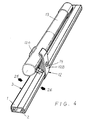
- So-called "open" profile lengths 1, 2, which can exhibit a desired length and can consist of aluminium or some other suitable metal, or even of a plastic material, and which are so arranged as to be capable of being connected together to produce a "closed" channel structure 3 along the effective external periphery of the profile lengths, comprise an arrangement 4 which permits two profile lengths 1, 2 of mutually identical execution to be connected together to produce a channel structure 3 of the aforementioned kind, thereby avoiding the need for the production and storage of profile lengths of different kinds.
- Said arrangement 4 involves each profile length 1, 2, which can be produced by a previously disclosed method, for example by extrusion, having its own flange 5 with the desired external form which it is wished to impart to the assembled closed channel structure 3 and also a number of connecting elements 7, 8, 9 projecting from a common base 6 for the profile length.
- Two mutually identical profile lengths 1, 2 are thus so arranged as to be capable of being connected together, in the positions I and II in which they are turned so that their channel-shaped spaces 10 face towards one another or at least face towards a common imaginary plane 11 situated between said two profile lengths 1, 2, through the interaction between said flanges and connecting elements 5, 7; 8, 9; 9, 8; 7,5.
- Said formed flange 5 may appropriately exhibit rounded form, as illustrated in the drawings, or may have some other angled form which deviates from straight form, intended to permit it to be connected to holders 12 so arranged as to engage around both the assembled channel structure 3 and a support 13, for example in the form of a tube, a post or a beam of some other kind.
- the holder 12 can be executed in the form of a divided holder 12A, 12B, which engages closely around the structure 3 and the support 13 to either side of a clamping bolt 14.
- One end 6A of the base 6 of the profile lengths may appropriately exhibit a flange part 15, which is so arranged as to constitute an extension of the closely-fitting connecting flange 5 on the second profile length 1, 2.
- One of said connecting elements can be constituted by an essentially straight flange 7, which can be accommodated in the space 10 within a closely-fitting connecting flange 5 in a complementary profile length 1, 2.
- each lateral flange Arranged on the side 5A, 7A of each lateral flange are connecting devices 16, 17 which are capable of interacting with one another in pairs for the purpose of retaining the two profile lengths 1, 2 in question in the positions III, IV next to one another in relation to one another, and said connecting devices can appropriately be formed from an area of greater cross-section 16, 17 projecting laterally from the associated flange 5, 7, which area of greater cross-section extends for the desired distance in the longitudinal sense of the associated profile length.
- a number of connecting elements 8, 9 on each profile length 1, 2, which project from the base 6 of each profile length, are so arranged as to divide the internal space 10 of the channel structure into a number of subsidiary spaces 10A, 10B, 10C extending in the longitudinal sense of the channel structure, the function of which will be described later.
- Connecting elements 8, 9 can also be executed respectively as female 9 and male 8, strip-shaped components, as shown in the drawings.
- the profile length is able to accommodate LEDs 18 and a casing bracket 19 for a diode lens 20 in appropriate holes 21, so that the assembled channel structure 3 can be utilized for lighting applications, primarily as decorative lighting and/or boundary lighting.
- a previously disclosed diode arrangement may be found, for example, in SE Patent Application 8501110-4.
- a wiring conductor 22 for said LEDs 18 can be arranged inside the internal space 10B of the channel structure, where it is accommodated in such a way as to extend along the structure for series and/or parallel connection as desired, and for connection to a suitable power supply and control unit, etc.
- connection of two profile lengths 1, 2 to one another is made possible either by their being moved in a direction 23, 24 towards one another and into a position in which they are turned so that their respective spaces 10A-10C face towards one another, such that the connecting devices 16, 17 engage behind one another and hold the assembled closed channel structure 3 together, or by their first being positioned slightly displaced from one another at the level at which it is intended that the two profile lengths 1, 2 should be connected together, whereupon they are displaced relative to one another in their longitudinal sense 25, 26, so that the connecting devices 16, 17 are situated behind one another without snapping, and so that the flanges 8, 9 are situated adjacent to one another in pairs.
- Dismantling of the channel structure 3 is effected in the reverse sequence to that outlined above.
- Said spaces 10A-10C in the structure 3 are able to function partly as an accommodating space for various conductors and other devices, although they also constitute an effective moisture barrier and thus effectively prevent dampness from finding its way in easily into the centre of the structure.
Landscapes
- Engineering & Computer Science (AREA)
- Architecture (AREA)
- Civil Engineering (AREA)
- Structural Engineering (AREA)
- General Engineering & Computer Science (AREA)
- Mutual Connection Of Rods And Tubes (AREA)
- Joining Of Building Structures In Genera (AREA)
- Paper (AREA)
- Breeding Of Plants And Reproduction By Means Of Culturing (AREA)
- Cartons (AREA)
- Prostheses (AREA)
- Stacking Of Articles And Auxiliary Devices (AREA)
- Outside Dividers And Delivering Mechanisms For Harvesters (AREA)
Claims (8)
- Anordnung für offene Profillängen (1, 2), die dazu vorgesehen ist, diese miteinander verbinden zu können, um eine Kanalkonstruktion (3) zu schaffen, welche rund um ihre Peripherie geschlossen ist, die zwei Profillängen (1, 2) von identischer Ausgestaltung umfaßt, von denen jede ihren eigenen Flansch (5) mit der gewünschten äußeren Gestalt und eine Anzahl von von einer gemeinsamen Basis (6) vorragenden Verbindungselementen (7 - 9) hat, wobei die genannten Profillängen (1, 2) mit ihren rinnenartigen Räumen (10) einander zugewandt angeordnet sind, so daß sie durch die Wechselwirkung zwischen an der Seite (5A, 7A) eines jeglichen seitlichen Flansches (5) sowie Verbindungselements (7) ausgestalteten Verbindungseinrichtungen, die aus hakenförmigen, seitlich herausragenden sowie längs des besagten Flansches sich erstreckenden Bereichen (16, 17) größeren Querschnitts heraus ausgebildet sind, zusammenzufügen sind, wobei die Verbindungseinrichtungen (16, 17) imstande sind, paarweise miteinander zu dem Zweck in Wechselwirkung zu kommen, um die genannten Profillängen (1, 2) mit Bezug zueinander in Position festzuhalten, dadurch gekennzeichnet, daß das eine Ende (6A) der erwähnten Basis (6) ein Wulstteil (15) aufweist, das so ausgestaltet ist, daß es eine Verlängerung des besagten Verbindungsflansches (5) der genannten gegenüberliegenden Profillänge (1, 2) bildet.
- Anordnung nach Patentanspruch 1, dadurch gekennzeichnet daß der besagte Flansch (5) eine gerundete Gestalt oder irgendeine andere abgewinkelte Gestalt, die von einer geraden Gestalt abweicht, aufweist.
- Anordnung nach irgendeinem der vorhergehenden Patentansprüche, dadurch gekennzeichnet, daß ein Flansch (7) an jeder Profillänge (1, 2) eine im wesentlichen gerade Gestalt aufweist.
- Anordnung nach irgendeinem der vorhergehenden Patentansprüche, dadurch gekennzeichnet, daß Verbindungselemente (8, 9), die von der Basis (6) einer jeden Profillänge vorstehen, so angeordnet sind, daß sie den inneren Raum (10) der Kanalkonstruktion in eine Anzahl von sich in der Längsrichtung der Kanalkonstruktion erstreckenden Nebenkammern(10A - 10C) teilen.
- Anordnung nach Patentanspruch 4, dadurch gekennzeichnet, daß die Verbindungselemente (8, 9) jeweils als leistenförmige Aufnahme- (9) und Einsteck-(8)Bauteile ausgebildet sind.
- Anordnung nach einem der vorhergehenden Patentansprüche, dadurch gekennzeichnet, daß die Außenoberfläche (6B) der Basis der Profillänge, welche von deren Mitte abgewandt ist, im wesentlichen eine ebene Gestalt mit Löchern (21) zur Aufnahme einer Leuchtdiode (18) oder eines Gehäuseträgers (19) aufweist.
- Anordnung nach Patentanspruch 6, dadurch gekennzeichnet, daß der innere Raum (10) der derart ausgebildeten Kanalkonstruktion so eingerichtet ist, um den Drahtleiter (22) für Leuchtdioden für eine Serien- und/oder Parallelschaltung aufzunehmen.
- Anordnung nach einem der vorhergehenden Patentansprüche, dadurch gekennzeichnet, daß in passenden Löchern (21) in einer Basis (6) einer Profillänge (1, 2) Leuchtdioden (18) und Gehäuseträger (19) aufgenommen sind, so daß die zusammengebaute Kanalkonstruktion (3) für Beleuchtungszwecke primär als dekorative Beleuchtung und/oder als Grenzbeleuchtung verwendet werden kann.
Priority Applications (1)
| Application Number | Priority Date | Filing Date | Title |
|---|---|---|---|
| AT88906166T ATE86726T1 (de) | 1987-06-26 | 1988-06-15 | Anordnung von laengen offener profile. |
Applications Claiming Priority (2)
| Application Number | Priority Date | Filing Date | Title |
|---|---|---|---|
| SE8702652A SE457824B (sv) | 1987-06-26 | 1987-06-26 | Anordning vid oeppna profilstycken |
| SE8702652 | 1987-06-26 |
Publications (2)
| Publication Number | Publication Date |
|---|---|
| EP0365585A1 EP0365585A1 (de) | 1990-05-02 |
| EP0365585B1 true EP0365585B1 (de) | 1993-03-10 |
Family
ID=20368990
Family Applications (1)
| Application Number | Title | Priority Date | Filing Date |
|---|---|---|---|
| EP88906166A Expired - Lifetime EP0365585B1 (de) | 1987-06-26 | 1988-06-15 | Anordnung von längen offener profile |
Country Status (7)
| Country | Link |
|---|---|
| US (1) | US5031083A (de) |
| EP (1) | EP0365585B1 (de) |
| AT (1) | ATE86726T1 (de) |
| AU (1) | AU1988688A (de) |
| DE (1) | DE3879210D1 (de) |
| SE (1) | SE457824B (de) |
| WO (1) | WO1988010396A1 (de) |
Families Citing this family (57)
| Publication number | Priority date | Publication date | Assignee | Title |
|---|---|---|---|---|
| NL8901136A (nl) * | 1989-05-03 | 1990-12-03 | Attema Kunststoffenind | Kokerstelsel voor elektrische leidingen, en hulpstukken voor een dergelijk stelsel. |
| US5931417A (en) * | 1992-06-02 | 1999-08-03 | Mobile Communications Holdings, Inc. | Non-geostationary orbit satellite constellation for continuous coverage of northern latitudes above 25° and its extension to global coverage tailored to the distribution of populated land masses on earth |
| DE4300819A1 (de) * | 1993-01-15 | 1994-07-21 | Peter Josef Korzilius Soehne G | Verkleidungselement mit Leuchtleiste |
| USD361153S (en) | 1993-03-25 | 1995-08-08 | Mark Fernandes | Support bar for floodlights |
| US5412552A (en) * | 1993-03-25 | 1995-05-02 | Fernandes; Mark | Lighting lamp bar |
| USD359374S (en) | 1993-09-03 | 1995-06-13 | International Lighting Manufacturing Company | Light fixture |
| US5613339A (en) * | 1993-12-01 | 1997-03-25 | Heritage Vinyl Products, Inc. | Deck plank and cover |
| US5426572A (en) * | 1993-12-01 | 1995-06-20 | International Lighting Manufacturing Company | Light fixtures |
| DE9319206U1 (de) * | 1993-12-16 | 1994-11-10 | Julius & August Erbslöh GmbH & Co, 42553 Velbert | Profil für die Bildung von Gerüstkonstruktionen |
| DE4402685A1 (de) * | 1994-01-29 | 1995-08-03 | Krupp Stahl Kaltform | Bohlenartige Metallplatte |
| USD374737S (en) | 1995-07-31 | 1996-10-15 | WAC Lighting Co. | Lamp |
| US5544028A (en) * | 1995-10-16 | 1996-08-06 | A/C Enterprises, Inc. | Light system with light holder |
| US5657590A (en) * | 1996-01-24 | 1997-08-19 | Quanex Corporation | Muntin bar assembly |
| US5772312A (en) * | 1996-10-30 | 1998-06-30 | Pihl-Niederman; Susan M. | Lighted holiday ornament |
| DE29620103U1 (de) * | 1996-11-20 | 1997-01-09 | Altura Leiden Holding B.V., Vianen | Verbindungsanordnung |
| US5758456A (en) * | 1996-12-04 | 1998-06-02 | Royal Plastics Group | Deck plank |
| US6033088A (en) * | 1997-06-23 | 2000-03-07 | Contigiani; Frank | Decorative lighting systems |
| US5881508A (en) * | 1997-10-15 | 1999-03-16 | Materials International, Inc. | Decking extrusion |
| US6088967A (en) * | 1998-01-02 | 2000-07-18 | Johnson; Wayne A | Closing string light display box |
| US6385941B1 (en) * | 2000-02-17 | 2002-05-14 | America Pre-Fab, Inc. | Simple lap beam |
| DE10106961A1 (de) * | 2001-02-15 | 2002-08-29 | Happich Fahrzeug & Ind Teile | Bleuchtungseinrichtung |
| US6601362B1 (en) * | 2001-09-12 | 2003-08-05 | Richard T. Prince | Variable load capacity construction components for patio pool enclosures |
| US20050262789A1 (en) * | 2002-03-14 | 2005-12-01 | Novoa Pablo R | Modular construction assembly |
| WO2003101940A2 (de) | 2002-05-31 | 2003-12-11 | Henkel Kommanditgesellschaft Auf Aktien | Desodorierung von kationischen ammoniumacetonitrilderivaten |
| US6971196B2 (en) | 2002-07-24 | 2005-12-06 | National Signal, Inc. | Message sign |
| DE20302604U1 (de) * | 2003-02-17 | 2003-06-26 | Weiß, Helge, 24626 Groß Kummerfeld | Strahleranordnung |
| JP2006256003A (ja) * | 2005-03-16 | 2006-09-28 | Honda Motor Co Ltd | 構造板 |
| US20070211462A1 (en) * | 2006-03-07 | 2007-09-13 | Dowell Robbie A | Accessory attachment apparatus |
| ITMC20070044A1 (it) * | 2007-02-28 | 2008-09-01 | Compagnucci Holding Spa | Mobile pensile per cucine componibili. |
| USD581580S1 (en) * | 2007-03-28 | 2008-11-25 | International Growers Supply Incorporated | Ballast cover |
| US20080250737A1 (en) * | 2007-04-10 | 2008-10-16 | Brian Hall | Extruded Structural Beam |
| USD620618S1 (en) | 2008-01-16 | 2010-07-27 | Teffenhart Jr Thomas Joseph | Self-mating beam |
| US7877962B2 (en) | 2008-01-16 | 2011-02-01 | Teffenhart Jr Thomas Joseph | System and method having an improved self-mating beam |
| USD634063S1 (en) | 2008-08-05 | 2011-03-08 | Lunera Lighting, Inc. | Extrusion for a flat panel LED fixture |
| US7854527B2 (en) * | 2009-02-25 | 2010-12-21 | Anderson Kenneth E | Combination LED fixture and raceway |
| US20110308191A1 (en) * | 2010-06-16 | 2011-12-22 | Mcnamee Steve V | Panel capture frame |
| US9222645B2 (en) | 2010-11-29 | 2015-12-29 | RTC Industries, Incorporated | LED lighting assembly and method of lighting for a merchandise display |
| US11274808B2 (en) | 2010-06-17 | 2022-03-15 | Rtc Industries, Inc. | LED lighting assembly and method of lighting for a merchandise display |
| US9913083B2 (en) | 2010-07-15 | 2018-03-06 | Dean R. Rosendahl | Joint for extruded panels |
| US8333291B2 (en) | 2010-07-15 | 2012-12-18 | Rosendahl Dean R | Housing formed from extruded panels |
| DE102010042377A1 (de) * | 2010-10-13 | 2012-04-19 | Osram Ag | Profilschiene, Verbindungselement, Leuchtmodul, Leuchtsystem und Leuchtkasten |
| USD663068S1 (en) * | 2011-11-29 | 2012-07-03 | Full Throttle Films, Inc. | Linear lighting track |
| USD662653S1 (en) * | 2011-11-29 | 2012-06-26 | Full Throttle Films, Inc. | Linear lighting track mount |
| USD665123S1 (en) * | 2011-12-31 | 2012-08-07 | Q Technology, Inc. | Lighting system bracket |
| AU344167S (en) * | 2012-02-24 | 2012-09-05 | Oak Moore Pty Ltd | A fridge shelf display device |
| US9261263B2 (en) * | 2012-04-23 | 2016-02-16 | Tempo Industries, Llc | Commercial lighting integrated platform |
| USD715994S1 (en) * | 2013-07-31 | 2014-10-21 | Sylwester Klus | Housing for LED-based lighting apparatus |
| US20160169462A1 (en) * | 2014-12-13 | 2016-06-16 | James Bradford Hawkins | Track system for light emitting diode (led) fixture |
| USD812782S1 (en) | 2016-04-04 | 2018-03-13 | White Distribution, LLC | Self mating beam |
| AT15904U3 (de) * | 2018-03-05 | 2018-09-15 | Helmut Kremser Ing | Geländer |
| FR3079522B1 (fr) | 2018-03-30 | 2020-02-28 | Ascodero Productique | Dispositif configure pour le maltage de grains, a fonctionnement discontinu |
| USD919420S1 (en) | 2018-06-21 | 2021-05-18 | Thomas Joseph Teffenhart, JR. | Corner coupler |
| US10640968B2 (en) | 2018-06-21 | 2020-05-05 | Thomas Joseph Teffenhart, JR. | System and method having an improved beam and beam coupling system |
| CN113795453B (zh) * | 2019-01-22 | 2023-10-03 | 邦德派公司 | 三层车辆升降机 |
| US11715944B1 (en) | 2019-01-22 | 2023-08-01 | Titan3 Technology LLC | Expandable cord protector |
| US11149439B2 (en) * | 2019-07-29 | 2021-10-19 | Frame & Mullions LLC | Surface mounted cable and tray molding |
| USD987121S1 (en) * | 2021-04-21 | 2023-05-23 | PMK Products, LLC | Extrusion |
Family Cites Families (13)
| Publication number | Priority date | Publication date | Assignee | Title |
|---|---|---|---|---|
| US3081851A (en) * | 1961-03-17 | 1963-03-19 | Kawneer Co | Metal construction element |
| US3222841A (en) * | 1962-10-08 | 1965-12-14 | Aire Lite Ind Inc | Screen enclosure |
| US3297075A (en) * | 1964-01-28 | 1967-01-10 | Reynolds Metals Co | Snap-locking fixtures for interior decorating |
| US3332197A (en) * | 1964-06-30 | 1967-07-25 | James L Hinkle | Interlocked structural assemblies and stiffeners therefor |
| US3596427A (en) * | 1969-03-14 | 1971-08-03 | Orbit International Inc | Panel post joining means |
| US3792250A (en) * | 1970-05-05 | 1974-02-12 | Progressive Dynamics | Light fixture with removable lens |
| DE2053100A1 (de) * | 1970-10-29 | 1972-06-22 | Betonwerk München Schiedel-Kamin, 8000 München | Mehrteiliges, durch Profilstücke zusammengesetztes Bauteil |
| DK125512B (da) * | 1970-11-11 | 1973-03-05 | Kramme & Zeuthen As | Kassedrager, navnlig til lagerreoler. |
| US3934105A (en) * | 1974-05-09 | 1976-01-20 | Amp Incorporated | Miniature switch with lighted indicator |
| AU545892B2 (en) * | 1980-07-30 | 1985-08-08 | Brownbuilt Ltd. | Elongate channel section |
| DE8330300U1 (de) * | 1983-10-18 | 1984-04-12 | Semperlux Gmbh, 1000 Berlin | Leuchte mit begleitender linearer lichtquelle |
| FR2568668B3 (fr) * | 1984-08-03 | 1986-09-05 | Profilafroid Sa | Longeron de casier. |
| US4654765A (en) * | 1985-09-23 | 1987-03-31 | Laidman Jerry H | Low voltage lighting system replaceable bulb assembly |
-
1987
- 1987-06-26 SE SE8702652A patent/SE457824B/sv not_active IP Right Cessation
-
1988
- 1988-06-15 US US07/438,418 patent/US5031083A/en not_active Expired - Fee Related
- 1988-06-15 DE DE8888906166T patent/DE3879210D1/de not_active Expired - Lifetime
- 1988-06-15 EP EP88906166A patent/EP0365585B1/de not_active Expired - Lifetime
- 1988-06-15 WO PCT/SE1988/000324 patent/WO1988010396A1/en not_active Ceased
- 1988-06-15 AU AU19886/88A patent/AU1988688A/en not_active Abandoned
- 1988-06-15 AT AT88906166T patent/ATE86726T1/de not_active IP Right Cessation
Also Published As
| Publication number | Publication date |
|---|---|
| ATE86726T1 (de) | 1993-03-15 |
| SE8702652D0 (sv) | 1987-06-26 |
| AU1988688A (en) | 1989-01-19 |
| DE3879210D1 (de) | 1993-04-15 |
| EP0365585A1 (de) | 1990-05-02 |
| SE457824B (sv) | 1989-01-30 |
| US5031083A (en) | 1991-07-09 |
| WO1988010396A1 (en) | 1988-12-29 |
Similar Documents
| Publication | Publication Date | Title |
|---|---|---|
| EP0365585B1 (de) | Anordnung von längen offener profile | |
| US5752781A (en) | Fiber trough coupling | |
| US4723747A (en) | Bar hangers for recessed lighting fixtures | |
| US4323319A (en) | Structural connecting member | |
| CA2277587C (en) | Fence system with variable position rail | |
| US6189273B1 (en) | Connector clip for drywall reveal | |
| US4907767A (en) | Stackable modular duct assemblies | |
| EP0260740A2 (de) | Führung für ein biegsames Kabel mit in zwei Richtungen beweglichen Verbindungsgliedern | |
| EP2630407B1 (de) | Oled-leuchtmittel für eine leuchte | |
| EP1546604B1 (de) | Beleuchtungsvorrichtung | |
| DE102012202148A1 (de) | Lichtbandsystem | |
| USD318343S (en) | Supporting channel for wall mounted track lighting system | |
| GB2318221A (en) | A wire manager capable of being removably mounted to stand-off | |
| FR2767422B1 (fr) | Connecteur electrique a deverrouillage par traction | |
| EP3369986B1 (de) | Leuchte | |
| DE3885474T2 (de) | Baukastensystem zur Herstellung von Leitungen zur Aufnahme von elektrischen Kabeln und dergleichen. | |
| USD318139S (en) | Supporting channel for wall mounted track lighting system | |
| EP3366981B1 (de) | Leuchtenwanne zum bilden eines leuchtengehäuses | |
| CH694820A5 (de) | Modulares Lichtsystem. | |
| EP1264137B2 (de) | Leuchte, insbesondere einbauleuchte | |
| GB2144974A (en) | A support bracket for a wall mounted rack system | |
| IE921218A1 (en) | Improvements in and relating to trunking | |
| AU6171599A (en) | Support with multipart trunking cover portion for equipment to be placed along trunking | |
| GB2174783A (en) | Jointing system | |
| CN222543777U (zh) | 一种灯条扣件及灯条 |
Legal Events
| Date | Code | Title | Description |
|---|---|---|---|
| PUAI | Public reference made under article 153(3) epc to a published international application that has entered the european phase |
Free format text: ORIGINAL CODE: 0009012 |
|
| 17P | Request for examination filed |
Effective date: 19891127 |
|
| AK | Designated contracting states |
Kind code of ref document: A1 Designated state(s): AT BE CH DE FR GB IT LI LU NL SE |
|
| 17Q | First examination report despatched |
Effective date: 19910607 |
|
| GRAA | (expected) grant |
Free format text: ORIGINAL CODE: 0009210 |
|
| AK | Designated contracting states |
Kind code of ref document: B1 Designated state(s): AT BE CH DE FR GB IT LI LU NL SE |
|
| PG25 | Lapsed in a contracting state [announced via postgrant information from national office to epo] |
Ref country code: IT Free format text: LAPSE BECAUSE OF FAILURE TO SUBMIT A TRANSLATION OF THE DESCRIPTION OR TO PAY THE FEE WITHIN THE PRE;WARNING: LAPSES OF ITALIAN PATENTS WITH EFFECTIVE DATE BEFORE 2007 MAY HAVE OCCURRED AT ANY TIME BEFORE 2007. THE CORRECT EFFECTIVE DATE MAY BE DIFFERENT FROM THE ONE RECORDED.SCRIBED TIME-LIMIT Effective date: 19930310 Ref country code: SE Effective date: 19930310 Ref country code: NL Effective date: 19930310 Ref country code: AT Effective date: 19930310 Ref country code: DE Effective date: 19930310 Ref country code: FR Effective date: 19930310 Ref country code: CH Effective date: 19930310 Ref country code: BE Effective date: 19930310 Ref country code: LI Effective date: 19930310 |
|
| REF | Corresponds to: |
Ref document number: 86726 Country of ref document: AT Date of ref document: 19930315 Kind code of ref document: T |
|
| REF | Corresponds to: |
Ref document number: 3879210 Country of ref document: DE Date of ref document: 19930415 |
|
| PG25 | Lapsed in a contracting state [announced via postgrant information from national office to epo] |
Ref country code: GB Effective date: 19930615 |
|
| REG | Reference to a national code |
Ref country code: CH Ref legal event code: PL |
|
| PG25 | Lapsed in a contracting state [announced via postgrant information from national office to epo] |
Ref country code: LU Free format text: LAPSE BECAUSE OF NON-PAYMENT OF DUE FEES Effective date: 19930630 |
|
| EN | Fr: translation not filed | ||
| NLV1 | Nl: lapsed or annulled due to failure to fulfill the requirements of art. 29p and 29m of the patents act | ||
| PLBE | No opposition filed within time limit |
Free format text: ORIGINAL CODE: 0009261 |
|
| STAA | Information on the status of an ep patent application or granted ep patent |
Free format text: STATUS: NO OPPOSITION FILED WITHIN TIME LIMIT |
|
| GBPC | Gb: european patent ceased through non-payment of renewal fee |
Effective date: 19930615 |
|
| 26N | No opposition filed |