EP0365080B1 - Stacking trolley and table intended for such a trolley - Google Patents
Stacking trolley and table intended for such a trolley Download PDFInfo
- Publication number
- EP0365080B1 EP0365080B1 EP89202569A EP89202569A EP0365080B1 EP 0365080 B1 EP0365080 B1 EP 0365080B1 EP 89202569 A EP89202569 A EP 89202569A EP 89202569 A EP89202569 A EP 89202569A EP 0365080 B1 EP0365080 B1 EP 0365080B1
- Authority
- EP
- European Patent Office
- Prior art keywords
- tray
- leg
- support rod
- legs
- tables
- Prior art date
- Legal status (The legal status is an assumption and is not a legal conclusion. Google has not performed a legal analysis and makes no representation as to the accuracy of the status listed.)
- Expired - Lifetime
Links
- 238000007789 sealing Methods 0.000 claims description 7
- 230000002093 peripheral effect Effects 0.000 claims description 4
- 238000010276 construction Methods 0.000 description 3
- 229920001971 elastomer Polymers 0.000 description 3
- 230000000284 resting effect Effects 0.000 description 3
- 239000004568 cement Substances 0.000 description 1
- 239000000806 elastomer Substances 0.000 description 1
- 239000000463 material Substances 0.000 description 1
- 239000007787 solid Substances 0.000 description 1
- 238000003466 welding Methods 0.000 description 1
Images


Classifications
-
- A—HUMAN NECESSITIES
- A47—FURNITURE; DOMESTIC ARTICLES OR APPLIANCES; COFFEE MILLS; SPICE MILLS; SUCTION CLEANERS IN GENERAL
- A47B—TABLES; DESKS; OFFICE FURNITURE; CABINETS; DRAWERS; GENERAL DETAILS OF FURNITURE
- A47B7/00—Tables of rigid construction
- A47B7/02—Stackable tables; Nesting tables
-
- A—HUMAN NECESSITIES
- A47—FURNITURE; DOMESTIC ARTICLES OR APPLIANCES; COFFEE MILLS; SPICE MILLS; SUCTION CLEANERS IN GENERAL
- A47B—TABLES; DESKS; OFFICE FURNITURE; CABINETS; DRAWERS; GENERAL DETAILS OF FURNITURE
- A47B87/00—Sectional furniture, i.e. combinations of complete furniture units, e.g. assemblies of furniture units of the same kind such as linkable cabinets, tables, racks or shelf units
- A47B87/02—Sectional furniture, i.e. combinations of complete furniture units, e.g. assemblies of furniture units of the same kind such as linkable cabinets, tables, racks or shelf units stackable ; stackable and linkable
- A47B87/0207—Stackable racks, trays or shelf units
- A47B87/0223—Shelves stackable by means of poles or tubular members as distance-holders therebetween
-
- B—PERFORMING OPERATIONS; TRANSPORTING
- B62—LAND VEHICLES FOR TRAVELLING OTHERWISE THAN ON RAILS
- B62B—HAND-PROPELLED VEHICLES, e.g. HAND CARTS OR PERAMBULATORS; SLEDGES
- B62B3/00—Hand carts having more than one axis carrying transport wheels; Steering devices therefor; Equipment therefor
-
- B—PERFORMING OPERATIONS; TRANSPORTING
- B62—LAND VEHICLES FOR TRAVELLING OTHERWISE THAN ON RAILS
- B62B—HAND-PROPELLED VEHICLES, e.g. HAND CARTS OR PERAMBULATORS; SLEDGES
- B62B2202/00—Indexing codes relating to type or characteristics of transported articles
- B62B2202/70—Flowers; Pots; Plants
Definitions
- the invention relates in the first instance to a stacking trolley comprising a mobile subframe with a number of tables fitted thereon above one another, said tables each having a tray forming a table top, and legs.
- Each table of this known trolley consists of two opposite H-shaped tubular sections and a tray resting on these sections. The tables can easily be removed from the trolley.
- the object of the invention is to enable the tables to be stacked on one another at mutually different intervals.
- the stacking trolley is therefore characterized by a vertical support rod in the vicinity of each leg, of each set consisting of one leg and one support rod one projects both above and below the tray with the various portions projecting above and below the tray having different vertical lengths, such that different intervals between the trays can be obtained by different combinations of portion(s) projecting below a tray with the portion(s) above the tray of a subjacent table.
- each table is provided in the vicinity of each leg and support rod, with a tube-shaped receiving element for receiving the upper end of a portion projecting above the tray of a table stacked under it or for receiving the lower end of a portion projecting below the tray of a table stacked above it.
- the subframe is preferably provided with vertical support rods to support a lowermost table.
- the invention also relates to a stackable table, comprising a tray forming a table top, and legs.
- this table is characterized by a vertical support rod in the vicinity of each leg, of each set consisting of one leg and one support rod one projects both above and below the tray with the various portions projecting above and below the tray having different vertical lengths.
- each table is polygonal and at each corner is provided with two recesses, in one of which a table leg is secured and in the other of which a support rod is secured.
- the table also has a tube-shaped receiving element.
- the recesses at the corners are provided in a corner piece of which projecting end sections are each incorporated in a rectangular tube profile, said tube profiles forming upright side edges of the table.
- the tube profiles have an inwardly directed flange.
- the table top must rest on said flange in a watertight manner, for example by providing the flange with a sealing profile.
- Leakage can also be prevented by a substantially V-shaped sealing strip that grips a peripheral edge of the tray, which sealing strip has a fixing lip which rests on the flange underneath said peripheral edge strip.
- legs and support rods may be secured in the recesses of a corner piece by clamping pieces which are fixed with the aid of bolts.
- the legs and the support rods With at least two openings spaced apart lengthwise, the length over which the legs and support rods project with respect to the table top can be chosen.
- EP-A-024280 discloses a set of stackable tables each table having a tray forming a table top and legs. The tables can easily be removed and placed on the floor. However the tables cannot be stacked on one another at mutually different intervals.
- Figure 1 shows a stacking trolley with a first stack of a number of tables.
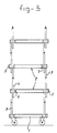
- Figure 2 shows a stacking trolley with a second stack of the said tables.
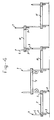
- Figure 3 shows a stacking trolley with a third stack of the said tables.
- Figure 4 shows a number of tables which are connected to one another and positioned alongside one another such that the table tops assume different heights.
- Figure 5 shows a top view of a first embodiment of a table frame.
- Figure 6 shows a perspective view of a part of the first embodiment of the table in the disassembled state.
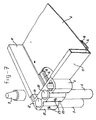
- Figure 7 shows a perspective view of the table according to Figure 6 in the assembled state.
- Figures 8 and 9 show perspective views of a corner section of a table according to a second embodiment, in the disassembled and the assembled state respectively.
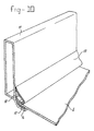
- Figure 10 shows a perspective view of a section of a table with an alternative seal of the table top with respect to the raised edge.
- the stacking trolley according to the invention is made up of a mobile sub-frame 1 and a number of tables 2 stacked thereon.
- the tables are rectangular and are provided at each corner point with a table leg 3, a support rod 4 and a pipe-piece-shaped receiving element 5.
- Each support rod 4 projects a relatively large distance above and a relatively small distance below the table top 6 of the particular table and is provided at the upper end with a conical stacking stud 7, which can be pushed into the lower end of a table leg 3, the lower end of a support rod 4 and a receiving element 5.
- each leg 4 is provided with a cap 8.
- the rectangular sub-frame 1 has a support rod 9 which projects above the supporting tray of the sub-frame over a distance which corresponds to the distance over which the support rods 4 of a table project above the table top 6.
- Figures 1 to 3 show various stable stacking possibilities for the tables 2 on an sub-frame 1.
- Figure 1 indicates that the support legs are resting on one another, the conical stacking stud 7 on the upper end of a support rod pushing into the lower end of a subsequent support rod.
- the legs 3 and the receiving elements 5 have no function with this stacking arrangement.
- Figure 2 shows that the conical stacking stud 7 at the upper end of the support rods is pushed into a receiving element 5 of a table.
- the legs 3 have no function with this stacking arrangement.
- Figure 3 indicates that each leg 3 is resting on the upper end of a support rod 4, the conical stacking stud 7 pushing into the lower end of the leg 3.
- the distance over which the support rods 4 project below a table top is less than the length of the legs 3.
- the distance over which the support rods 4 project above a table top is greater than the length of the legs 3.
- Figure 4 shows how the tables 2 and also the sub-frame 1 can be arranged alongside one another on the floor, with which arrangement the height of the table top can vary. Consequently, the flowers and plants can be presented to the public in an attractive manner without it being necessary to transfer or move the flowers and plants.
- the tables, with the flowers and plants supported thereon have been removed from the stacking trolley and positioned on the floor, they can be sprayed without being shifted, which is a not inappreciable advantage in practice.
- FIGS 5 to 10 show possible construction details.
- Each table has a frame consisting of four rectangular tube profiles 11 and four corner pieces 12. The corner pieces possess projecting sections 13 which are pushed into a tube profile 11 and welded thereto.
- Each tube profile 11 has an inwardly projecting flange 14.
- the table top 6 lies on the flanges 14 of the four tube profiles 11.
- the flanges 14 in the embodiment according to Figures 5 to 7 are provided with a sealing strip 16 of elastomer material or cement.
- a V-shaped rubber flap 17 seals the gap between the table top 6 and the tube profile 11.
- the flap 17 has a section 17' which is clamped between the flange 14 and the table top 6.
- the flap 17 is also held in place by a boss 18 of the tube profile gripping on an edge of the rubber flap.
- the corner pieces 12 comprise the receiving element 5, which is designed as a pipe piece, and two semi-cylindrical recesses 19, 20, which are intended to receive a leg 3 and a support rod 4 respectively.
- the legs 3, support rods 4 and semi-cylindrical parts 19, 20 are provided with an opening, so that each leg and each support rod can be secured in the desired position by means of a bolt 23, which projects through a clamping piece 21 and 22 respectively.
- the clamping pieces 21, 22 are in the form of semi-cylindrical dishes in the embodiment according to Figures 5-7 and in the form of semi-circular solid parts in the embodiment according to Figures 8 and 9.
- the corner pieces 12 can also be hook-shaped and project around each edge of the table.
- the height of said legs and/or rods 4 can be made adjustable.
- the legs 3, the support rods 4 and the receiving elements 5 of a table can also be secured in another manner, for example directly to the frame or to the table top, for example by welding. They must be positioned in a straight line in each unit, but can be fitted in a right-angle pattern.
- the essential feature of the inventive concept is that a number of tables provided with legs can be stacked in a stable manner on the mobile sub-frame 1 of a trolley. These tables can be placed, with the goods (flowers and plants) standing thereon, on the floor in a shop. The distance between the individual table tops is variable with the aid of support rods and receiving elements.
- the tables can also be triangular, pentagonal or hexagonal or with more sides, and can even be circular or ellipsical.
Landscapes
- Engineering & Computer Science (AREA)
- Chemical & Material Sciences (AREA)
- Combustion & Propulsion (AREA)
- Transportation (AREA)
- Mechanical Engineering (AREA)
- Handcart (AREA)
- Crushing And Grinding (AREA)
- Bending Of Plates, Rods, And Pipes (AREA)
- Rollers For Roller Conveyors For Transfer (AREA)
- Ceramic Products (AREA)
- Stacking Of Articles And Auxiliary Devices (AREA)
- Basic Packing Technique (AREA)
- Prostheses (AREA)
- Pharmaceuticals Containing Other Organic And Inorganic Compounds (AREA)
- Polysaccharides And Polysaccharide Derivatives (AREA)
- Liquid Crystal Substances (AREA)
- Bidet-Like Cleaning Device And Other Flush Toilet Accessories (AREA)
Priority Applications (1)
| Application Number | Priority Date | Filing Date | Title |
|---|---|---|---|
| AT89202569T ATE92411T1 (de) | 1988-10-18 | 1989-10-10 | Stapelwagen und tisch fuer solchen wagen. |
Applications Claiming Priority (2)
| Application Number | Priority Date | Filing Date | Title |
|---|---|---|---|
| NL8802569A NL8802569A (nl) | 1988-10-18 | 1988-10-18 | Stapelwagen en voor zo een wagen bestemde tafel. |
| NL8802569 | 1988-10-18 |
Publications (2)
| Publication Number | Publication Date |
|---|---|
| EP0365080A1 EP0365080A1 (en) | 1990-04-25 |
| EP0365080B1 true EP0365080B1 (en) | 1993-08-04 |
Family
ID=19853080
Family Applications (1)
| Application Number | Title | Priority Date | Filing Date |
|---|---|---|---|
| EP89202569A Expired - Lifetime EP0365080B1 (en) | 1988-10-18 | 1989-10-10 | Stacking trolley and table intended for such a trolley |
Country Status (9)
| Country | Link |
|---|---|
| US (1) | US5123552A (da) |
| EP (1) | EP0365080B1 (da) |
| AT (1) | ATE92411T1 (da) |
| DE (1) | DE68908072T2 (da) |
| DK (1) | DK170874B1 (da) |
| ES (1) | ES2042978T3 (da) |
| IE (1) | IE63830B1 (da) |
| NL (1) | NL8802569A (da) |
| NO (1) | NO172680C (da) |
Cited By (1)
| Publication number | Priority date | Publication date | Assignee | Title |
|---|---|---|---|---|
| KR20220155043A (ko) * | 2021-05-14 | 2022-11-22 | 정용선 | 레벨 리프트 |
Families Citing this family (13)
| Publication number | Priority date | Publication date | Assignee | Title |
|---|---|---|---|---|
| IL116377A (en) * | 1994-12-15 | 2003-05-29 | Cabot Corp | Reaction of carbon black with diazonium salts, resultant carbon black products and their uses |
| CA2214634A1 (en) * | 1995-03-10 | 1996-09-19 | Dornbierer, Andreas | Structural member unit for modular shelving |
| IT246533Y1 (it) * | 1999-02-19 | 2002-04-09 | Terry Store Age S P A | Struttura modulare componibile ad elementi modulari per la realizzazione di scaffali ed armadietti con ripiani |
| WO2004065267A2 (en) * | 2003-01-21 | 2004-08-05 | Wenger Corporation | Riser cart |
| US20060043094A1 (en) * | 2004-09-02 | 2006-03-02 | Farley Sean S | Modular machine for storage or transportation of compressed gas cylinders |
| US20060283824A1 (en) * | 2004-09-02 | 2006-12-21 | Discount Carts & Racks Inc. | Modular rack for transporting and horizontally storing gas cylinders |
| DE202005007939U1 (de) * | 2005-05-17 | 2006-09-28 | Wanzl Metallwarenfabrik Gmbh | Kommissionierwagen |
| US20080135698A1 (en) * | 2006-12-11 | 2008-06-12 | Tootsie Roll Industries, Inc. | Rack system |
| DE102009041219A1 (de) * | 2009-09-11 | 2011-03-24 | Bernd Bosch Maschinenbau | Reagenzglasgestell |
| GB2503193A (en) * | 2012-02-10 | 2013-12-25 | Belron Hungary Kft Zug Branch | Container with lifting means and securable to like containers |
| TWM469805U (zh) * | 2013-06-26 | 2014-01-11 | Ming-Chi Chen | 置物層架之組合結構 |
| KR102627355B1 (ko) * | 2021-06-25 | 2024-01-18 | 조용우 | 운반용 대차 |
| US11925154B1 (en) * | 2022-10-11 | 2024-03-12 | CGIP, Inc. | System for plant cultivation |
Family Cites Families (12)
| Publication number | Priority date | Publication date | Assignee | Title |
|---|---|---|---|---|
| NL6802097A (da) * | 1968-02-14 | 1969-08-18 | ||
| US3620176A (en) * | 1970-01-26 | 1971-11-16 | Hirsh Co | Trim fastenings for shelving unit |
| DK139747B (da) * | 1977-01-12 | 1979-04-09 | Variantsystemet As | Transportvogn med hylder og hjul. |
| DE2814422A1 (de) * | 1977-04-07 | 1979-03-01 | B C I Group Ltd Kk | Kupplungselement fuer rohrfoermige teile und mit solchen rohrteilen zusammengebaute gerueste |
| US4099472A (en) * | 1977-05-31 | 1978-07-11 | Kellogg Harlan F | Free standing shelving system |
| US4275666A (en) * | 1977-08-04 | 1981-06-30 | Dart Industries Inc. | Modular taboret kit |
| US4637324A (en) * | 1981-08-27 | 1987-01-20 | Janson Richard W | Furniture assembly and assembly device |
| US4620637A (en) * | 1985-09-09 | 1986-11-04 | Masashi Karashima | Trolley |
| US4706576A (en) * | 1986-03-27 | 1987-11-17 | Barry James | Interlocking plastic shelving system |
| GB2188691A (en) * | 1986-04-01 | 1987-10-07 | John William Stamper | Quick release plug |
| US4998023A (en) * | 1989-06-22 | 1991-03-05 | Lakeside Manufacturing, Inc. | Portable utility cart |
| US4981224A (en) * | 1989-11-15 | 1991-01-01 | The Howard Marlboro Marketing, Inc. | Stacking tray display |
-
1988
- 1988-10-18 NL NL8802569A patent/NL8802569A/nl not_active Application Discontinuation
-
1989
- 1989-10-10 AT AT89202569T patent/ATE92411T1/de not_active IP Right Cessation
- 1989-10-10 EP EP89202569A patent/EP0365080B1/en not_active Expired - Lifetime
- 1989-10-10 ES ES89202569T patent/ES2042978T3/es not_active Expired - Lifetime
- 1989-10-10 DE DE89202569T patent/DE68908072T2/de not_active Expired - Fee Related
- 1989-10-12 NO NO894068A patent/NO172680C/no unknown
- 1989-10-17 DK DK515289A patent/DK170874B1/da active
- 1989-10-17 IE IE333489A patent/IE63830B1/en not_active IP Right Cessation
-
1991
- 1991-04-08 US US07/682,258 patent/US5123552A/en not_active Expired - Fee Related
Cited By (1)
| Publication number | Priority date | Publication date | Assignee | Title |
|---|---|---|---|---|
| KR20220155043A (ko) * | 2021-05-14 | 2022-11-22 | 정용선 | 레벨 리프트 |
Also Published As
| Publication number | Publication date |
|---|---|
| EP0365080A1 (en) | 1990-04-25 |
| NO894068L (no) | 1990-04-19 |
| ES2042978T3 (es) | 1993-12-16 |
| NO172680B (no) | 1993-05-18 |
| NO172680C (no) | 1993-08-25 |
| IE893334L (en) | 1990-04-18 |
| NO894068D0 (no) | 1989-10-12 |
| ATE92411T1 (de) | 1993-08-15 |
| DK515289D0 (da) | 1989-10-17 |
| DK170874B1 (da) | 1996-02-26 |
| DE68908072T2 (de) | 1994-02-03 |
| DE68908072D1 (de) | 1993-09-09 |
| IE63830B1 (en) | 1995-06-14 |
| NL8802569A (nl) | 1990-05-16 |
| US5123552A (en) | 1992-06-23 |
| DK515289A (da) | 1990-04-19 |
Similar Documents
| Publication | Publication Date | Title |
|---|---|---|
| EP0365080B1 (en) | Stacking trolley and table intended for such a trolley | |
| USRE42988E1 (en) | Wire chafing stand | |
| US4914857A (en) | Tomato vine supporting device | |
| US4635563A (en) | Adjustable shelving system | |
| US4199069A (en) | Rack | |
| CA1054572A (en) | Mobile truck provided with improved removable racks for pans, trays and the like | |
| US2801752A (en) | Modular stacking unit | |
| US5199676A (en) | Adjustable water heater stand | |
| US4056195A (en) | Supporting base for rack | |
| US5819941A (en) | Plant pallet | |
| US5263595A (en) | Modular rack system for use with removable pans | |
| US5996948A (en) | Wire chafing stand | |
| US5259141A (en) | Tree planter | |
| US4270463A (en) | Display stand with easily adjusted shelves | |
| CA2040321A1 (en) | Stacking trolley and table intended for such a trolley | |
| GB2177889A (en) | Plant support | |
| US6085460A (en) | System for holding plant containers | |
| GB2150110A (en) | Collapsible pallets | |
| EP0073640A1 (en) | Collapsible furniture | |
| US20230082006A1 (en) | System of racks for space saving storage | |
| USRE24984E (en) | Nesting and stacking trays | |
| GB2219479A (en) | Carrier and support for plants | |
| GB2336091A (en) | Gardening apparatus | |
| JP3012556U (ja) | 植木鉢台 | |
| JP3016188U (ja) | 長尺材の収納装置 |
Legal Events
| Date | Code | Title | Description |
|---|---|---|---|
| PUAI | Public reference made under article 153(3) epc to a published international application that has entered the european phase |
Free format text: ORIGINAL CODE: 0009012 |
|
| AK | Designated contracting states |
Kind code of ref document: A1 Designated state(s): AT BE CH DE ES FR GB GR IT LI LU NL SE |
|
| 17P | Request for examination filed |
Effective date: 19900308 |
|
| 17Q | First examination report despatched |
Effective date: 19910819 |
|
| ITF | It: translation for a ep patent filed | ||
| GRAA | (expected) grant |
Free format text: ORIGINAL CODE: 0009210 |
|
| AK | Designated contracting states |
Kind code of ref document: B1 Designated state(s): AT BE CH DE ES FR GB GR IT LI LU NL SE |
|
| REF | Corresponds to: |
Ref document number: 92411 Country of ref document: AT Date of ref document: 19930815 Kind code of ref document: T |
|
| REF | Corresponds to: |
Ref document number: 68908072 Country of ref document: DE Date of ref document: 19930909 |
|
| ET | Fr: translation filed | ||
| EPTA | Lu: last paid annual fee | ||
| REG | Reference to a national code |
Ref country code: ES Ref legal event code: FG2A Ref document number: 2042978 Country of ref document: ES Kind code of ref document: T3 |
|
| REG | Reference to a national code |
Ref country code: GR Ref legal event code: FG4A Free format text: 3008951 |
|
| PLBE | No opposition filed within time limit |
Free format text: ORIGINAL CODE: 0009261 |
|
| STAA | Information on the status of an ep patent application or granted ep patent |
Free format text: STATUS: NO OPPOSITION FILED WITHIN TIME LIMIT |
|
| 26N | No opposition filed | ||
| EAL | Se: european patent in force in sweden |
Ref document number: 89202569.3 |
|
| PGFP | Annual fee paid to national office [announced via postgrant information from national office to epo] |
Ref country code: ES Payment date: 19971002 Year of fee payment: 9 |
|
| PGFP | Annual fee paid to national office [announced via postgrant information from national office to epo] |
Ref country code: GR Payment date: 19971009 Year of fee payment: 9 |
|
| PGFP | Annual fee paid to national office [announced via postgrant information from national office to epo] |
Ref country code: AT Payment date: 19971010 Year of fee payment: 9 |
|
| PGFP | Annual fee paid to national office [announced via postgrant information from national office to epo] |
Ref country code: GB Payment date: 19971013 Year of fee payment: 9 |
|
| PGFP | Annual fee paid to national office [announced via postgrant information from national office to epo] |
Ref country code: FR Payment date: 19971016 Year of fee payment: 9 |
|
| PGFP | Annual fee paid to national office [announced via postgrant information from national office to epo] |
Ref country code: SE Payment date: 19971023 Year of fee payment: 9 Ref country code: BE Payment date: 19971023 Year of fee payment: 9 |
|
| PGFP | Annual fee paid to national office [announced via postgrant information from national office to epo] |
Ref country code: LU Payment date: 19971112 Year of fee payment: 9 |
|
| PGFP | Annual fee paid to national office [announced via postgrant information from national office to epo] |
Ref country code: DE Payment date: 19971124 Year of fee payment: 9 |
|
| PGFP | Annual fee paid to national office [announced via postgrant information from national office to epo] |
Ref country code: CH Payment date: 19971204 Year of fee payment: 9 |
|
| PG25 | Lapsed in a contracting state [announced via postgrant information from national office to epo] |
Ref country code: LU Free format text: LAPSE BECAUSE OF NON-PAYMENT OF DUE FEES Effective date: 19981010 Ref country code: GB Free format text: LAPSE BECAUSE OF NON-PAYMENT OF DUE FEES Effective date: 19981010 Ref country code: AT Free format text: LAPSE BECAUSE OF NON-PAYMENT OF DUE FEES Effective date: 19981010 |
|
| PG25 | Lapsed in a contracting state [announced via postgrant information from national office to epo] |
Ref country code: SE Free format text: LAPSE BECAUSE OF NON-PAYMENT OF DUE FEES Effective date: 19981011 |
|
| PG25 | Lapsed in a contracting state [announced via postgrant information from national office to epo] |
Ref country code: ES Free format text: LAPSE BECAUSE OF THE APPLICANT RENOUNCES Effective date: 19981013 |
|
| PGFP | Annual fee paid to national office [announced via postgrant information from national office to epo] |
Ref country code: NL Payment date: 19981030 Year of fee payment: 10 |
|
| PG25 | Lapsed in a contracting state [announced via postgrant information from national office to epo] |
Ref country code: LI Free format text: LAPSE BECAUSE OF NON-PAYMENT OF DUE FEES Effective date: 19981031 Ref country code: GR Free format text: LAPSE BECAUSE OF NON-PAYMENT OF DUE FEES Effective date: 19981031 Ref country code: CH Free format text: LAPSE BECAUSE OF NON-PAYMENT OF DUE FEES Effective date: 19981031 Ref country code: BE Free format text: LAPSE BECAUSE OF NON-PAYMENT OF DUE FEES Effective date: 19981031 |
|
| BERE | Be: lapsed |
Owner name: FERALKON B.V. Effective date: 19981031 |
|
| GBPC | Gb: european patent ceased through non-payment of renewal fee |
Effective date: 19981010 |
|
| REG | Reference to a national code |
Ref country code: CH Ref legal event code: PL |
|
| EUG | Se: european patent has lapsed |
Ref document number: 89202569.3 |
|
| PG25 | Lapsed in a contracting state [announced via postgrant information from national office to epo] |
Ref country code: FR Free format text: LAPSE BECAUSE OF NON-PAYMENT OF DUE FEES Effective date: 19990630 |
|
| REG | Reference to a national code |
Ref country code: FR Ref legal event code: ST |
|
| PG25 | Lapsed in a contracting state [announced via postgrant information from national office to epo] |
Ref country code: DE Free format text: LAPSE BECAUSE OF NON-PAYMENT OF DUE FEES Effective date: 19990803 |
|
| PG25 | Lapsed in a contracting state [announced via postgrant information from national office to epo] |
Ref country code: NL Free format text: LAPSE BECAUSE OF NON-PAYMENT OF DUE FEES Effective date: 20000501 |
|
| NLV4 | Nl: lapsed or anulled due to non-payment of the annual fee |
Effective date: 20000501 |
|
| REG | Reference to a national code |
Ref country code: ES Ref legal event code: FD2A Effective date: 20001009 |
|
| PG25 | Lapsed in a contracting state [announced via postgrant information from national office to epo] |
Ref country code: IT Free format text: LAPSE BECAUSE OF NON-PAYMENT OF DUE FEES Effective date: 20051010 |