EP0363790A2 - Méthode pour la formation d'image et matériel - Google Patents
Méthode pour la formation d'image et matériel Download PDFInfo
- Publication number
- EP0363790A2 EP0363790A2 EP89118323A EP89118323A EP0363790A2 EP 0363790 A2 EP0363790 A2 EP 0363790A2 EP 89118323 A EP89118323 A EP 89118323A EP 89118323 A EP89118323 A EP 89118323A EP 0363790 A2 EP0363790 A2 EP 0363790A2
- Authority
- EP
- European Patent Office
- Prior art keywords
- group
- image forming
- light
- substituted
- forming medium
- Prior art date
- Legal status (The legal status is an assumption and is not a legal conclusion. Google has not performed a legal analysis and makes no representation as to the accuracy of the status listed.)
- Granted
Links
Images


Classifications
-
- G—PHYSICS
- G03—PHOTOGRAPHY; CINEMATOGRAPHY; ANALOGOUS TECHNIQUES USING WAVES OTHER THAN OPTICAL WAVES; ELECTROGRAPHY; HOLOGRAPHY
- G03F—PHOTOMECHANICAL PRODUCTION OF TEXTURED OR PATTERNED SURFACES, e.g. FOR PRINTING, FOR PROCESSING OF SEMICONDUCTOR DEVICES; MATERIALS THEREFOR; ORIGINALS THEREFOR; APPARATUS SPECIALLY ADAPTED THEREFOR
- G03F7/00—Photomechanical, e.g. photolithographic, production of textured or patterned surfaces, e.g. printing surfaces; Materials therefor, e.g. comprising photoresists; Apparatus specially adapted therefor
- G03F7/004—Photosensitive materials
- G03F7/027—Non-macromolecular photopolymerisable compounds having carbon-to-carbon double bonds, e.g. ethylenic compounds
- G03F7/028—Non-macromolecular photopolymerisable compounds having carbon-to-carbon double bonds, e.g. ethylenic compounds with photosensitivity-increasing substances, e.g. photoinitiators
- G03F7/0285—Silver salts, e.g. a latent silver salt image
Definitions
- the present invention relates to an image forming method that forms a polymer image by the action of light, and also to an image forming medium.
- Energy used to form or record an image include light, sound, electricity, magnetism, heat, radiations such as electron rays and X-rays, and chemical energy, among which, in particular, widely used are light, electricity, heat energy, or a combination of any of these.
- the image forming method that employs the combination of light energy with chemical energy includes a silver salt photographic process and a method in which a diazo copying paper is used.
- the method that employs the combination of light energy with electric energy includes an electrophotographic system.
- the method that utilizes heat energy includes a method in which a thermal recording paper or transfer recording paper is used.
- known as the method that utilizes electric energy is a method in which an electrostatic recording paper, electrothermal recording paper, or electrosensitive recording paper is used.
- the silver salt photographic process can obtain an image having a high resolution.
- the silver salt photographic process requires the developing and fixing that uses complicated liquid compositions, or the drying of an image (or a print).
- U.S. Patent No. 4,629,676 teaches a method in which polymerization reaction under dry (thermal) conditions is caused by the photosensitive reaction of silver halide that acts as a trigger, to form an image comprising a polymer.
- This method has the advantage that any complicated wet processing is not required, but has had the disadvantage that the polymer formation rate (i.e., polymerization rate of a polymeric compound) is so low that it takes a long time to form the polymer image.
- this disadvantage arises presumably because of a reaction intermediate (which functions as a polymerization initiator) formed in the course of heating, by the reaction between silver produced from silver halide by imagewise exposure and a reducing agent, which intermediate is so stable and has so low activity as the polymerization initiator that the polymerization reaction can not proceed so rapidly.
- Japanese Unexamined Patent Publication No. 70836/1987 discloses a method in which a thermal polymerization initiator is used.
- This method comprises forming a latent image comprising silver metal produced from silver halide by imagewise exposure, converting, under heating, a reducing agent into an oxidized product having a polymerization inhibitory power different from that of said reducing agent by utilizing a catalytic action of the above silver metal, thereby producing a difference in the polymerization inhibitory power between the reducing agent and the resulting oxidized product and also causing a thermal polymerization reaction utilizing the thermal polymerization initiator, thus forming a polymer image corresponding with the difference in the polymerization inhibitory power.
- the image formation according to this method is very unstable in that, for example, the areas on which the polymer is formed may turn into exposed areas or unexposed areas only because of a slight change in the amount of the reducing agent.
- U.S. Patent No. 4,649,098 discloses a method in which a reducing agent having a polymerization inhibitory power is brought into an oxidized product by imagewise consumption (at imagewise exposed areas) in the course of the developing of silver halide, and, after imagewise inhibition (at imagewise unexposed areas) of polymerization reaction by the action of the residual reducing agent, light energy is uniformly applied (whole areal exposure) from the outside to cause photopolymerization at the area at which the reducing agent has been consumed (imagewise exposed area), thus forming a polymer image.
- the above method has the advantages that it can achieve a high sensitivity in the writing of a latent image since the silver halide is used, and the steps from the writing for the formation of an image up to the whole areal exposure can be separated in a good efficiency. It, however, is difficult to obtain a polymer image having a sufficient contrast. This is caused for the following reason.
- the reducing agent used in the above method is in itself a reducing agent that acts as a polymerization inhibitor and turns not to act as the polymerization inhibitor after the reduction of silver halide.
- the reducing agent at the imagewise exposed area must be sufficiently converted into the oxidized product before the polymerization can be sufficiently achieved.
- the application of heat energy in an sufficient amount in carrying out the development, with the intention to sufficiently convert the reducing agent at the imagewise exposed area into the oxidized product may cause an unauthorized oxidation-reduction reaction at the imagewise unexposed areas.
- the application of heat energy in a reduced amount in carrying out the development may conversely make the conversion into the oxidized product at the imagewise exposed areas not to sufficiently proceed. Since in this instance the imagewise exposed area of an oxidation-reduction image is polymerized with difficulty, the light energy in carrying out the whole areal exposure must be applied in an increased amount. This may cause unnecessary polymerization at the unexposed areas with increase in the amount of the light energy.
- the silver metal is deposited at the area to be polymerized, the light energy of the whole areal exposure is absorbed so that the imagewise exposed area and unexposed area become different in the point of the irradiation energy. As a result, the polymerization at the unexposed area is more apt to proceed, eventually making it impossible to obtain the polymer image with a sufficient contrast.
- the polymer image to be formed according to the methods as described above is an image comprising a polymerized area and an unpolymerized area. Aiming at making this polymer image visible and further forming it into a color image, U.S. Patent No. 4,649,098 and so forth disclose various methods that utilize the difference in properties and so forth between the polymerized area and unpolymerized area.
- a treatment is made using a liquid that does not dissolve the polymerized area and dissolves the layer of the unpolymerized area, to dissolve out and remove the unpolymerized area (i.e., etching); a method in which, utilizing the difference in adhesion between the polymerized area and unpolymerized area, a sheet such as plastic film is adhered and thereafter peeled to separate the polymerized area and unpolymerized area under dry conditions (i.e., peeling-apart); in the case when the polymer image is formed into a color image, a method in which a photopolymerizable layer is previously colored with use of a pigment or dye, which is then subjected to dissolving-out (i.e, the above etching) or peeling (i.e., the above peeling-apart) to form the color image, or a method in which, utilizing the adhesion at the unpolymerized area, a coloring powder is applied to make selective
- Japanese Unexamined Patent Publication No. 55-50246 also discloses a photosensitive lithographic material that has a photopolymerizable composition layer, a transparent intermediate layer and a heat development type photosensitive composition layer, and is capable of forming a polymer image in the photopolymerizable composition layer with utilization of the light-absorption of the metallic silver which is produced a the exposed area of the heat development type photosensitive composition layer as a result of imagewise exposure and heating (a plate is finally obtained by peeling-apart).
- the metallic silver however, has so flat light-absorption characteristics that it is hard to say that the ability to absorb a particular wavelength is satisfactory. Hence, it is necessary for achieving sufficient absorption of light to make the photosensitive layer thick. This results in a lowering of the resolution of the polymer image.
- a method is employed in which the quantity of the organic silver salt per unit area is increased to achieve sufficient absorption of light, there also has been the problem that the storage stability of image forming mediums is lowered.
- An object of the present invention is to provide an image forming method, and an image forming medium, that can obtain an image having a superior resolution and contrast even with use of a small amount of organic silver salt.
- the image forming method of the present invention comprises: subjecting an image forming medium containing at least a photosensitive silver halide, an organic silver salt, a reducing agent, a polymerizable polymer precursor and a photopolymerization initiator, to imagewise exposure, followed by heating to produce a light-absorbing organic compound in said image forming medium; and subjecting said image forming medium in which said light-absorbing organic compound has been produced, to polymerization exposure to cause said polymerizable polymer precursor to polymerize; where te light-absorption characteristics of said light-absorbing organic compound are utilized to suppress the polymerization of said polymerizable polymer precursor at the area at which said light-absorbing organic compound has been produced.
- the image forming method of the present invention comprises; subjecting a photosensitive material containing at least a photosensitive silver halide, an organic silver salt and a reducing agent, to imagewise exposure, followed by heating to produce a light-absorbing organic compound in said photosensitive material; laminating a polymerization material containing at least a polymerizable polymer precursor and a photopolymerization initiator, on said photosensitive material in which said light-absorbing organic compound has been produced; and subjecting said photosensitive material and said polymerization material to polymerization exposure to cause said polymerizable polymer precursor to polymerize; where the light-absorption characteristics of said light-absorbing organic compound are utilized to suppress the polymerization of said polymerizable polymer precursor at the area at which said light-absorbing organic compound has been produced.
- the image forming medium of the present invention is characterized by containing at least i) a photosensitive silver halide, an organic silver salt and a reducing agent that react each other to produce a light-absorbing organic compound as a result of imagewise exposure and heating, ii) a polymerizable polymer precursor, and iii) a photopolymerization initiator; said light-absorbing organic compound being capable of absorbing light with wavelengths to which said photopolymerization initiator has a sensitivity.
- the image forming medium of the present invention comprises at least an image forming layer 1 provided on a support 2.
- the image forming layer 1 contains a photosensitive silver halide, an organic silver salt, a reducing agent, a polymerizable polymer precursor, and a photopolymerization initiator.
- the organic silver salt and reducing agent contained in the image forming layer 1 undergo oxidation-reduction reaction as a result of subjecting the image forming layer 1 to exposure and heating (heat development), and the oxidized product produced as a result of the reaction serves as the light-absorbing organic compound.
- the oxidized product produced as a result of the reaction between the organic silver salt and reducing agent further reacts with a coupler to produce the light-absorbing organic compound.
- the image forming layer 1 on the support 2 is, as shown in Fig. 1, first imagewise exposed to light in a desired form in the step of imagewise exposure, according to analog exposure using a mask or the like, or digital exposure in which exposure is carried out using a laser or the like according to image signals such as external electric signals or light signals (hv1).
- image signals such as external electric signals or light signals (hv1).
- silver metal 3 is produced from the photosensitive silver halide present in the imagewise exposed area 1a, and this forms a latent image.
- the silver metal 3 serves as a catalyst for the thermal reaction between the organic silver salt and reducing agent.
- conditions for the exposure to light in carrying out the writing of this latent image conditions under which the resulting polymer image can obtain the desired performance such as sufficient contrast may be used by appropriately selecting them depending on the concentration, type and so forth of the silver halide incorporated into the image forming layer.
- the image forming method of the present invention which employs the photosensitive silver halide in the step of imagewise exposure, enables highly sensitive writing.
- the image forming layer 1 in which the latent image has been formed is heated, so that as shown in Fig. 2 the silver metal 3 selectively acts as a catalyst in the imagewise exposed area 1a, where the organic silver salt reacts with the reducing agent.
- the organic silver salt is reduced to a silver atom (metallic silver) and at the same time the reducing agent is oxidized to form an oxidized product 5.
- This oxidized product 5 has light absorption.
- the oxidized product 5 further reacts with a coupler to produce an organic compound that exhibits light absorption.
- the heating in this heating step is carried out under appropriate selection of conditions necessary for the progress of oxidation-reduction reaction and the formation of the light-absorbing organic compound.
- the heating temperature depends on the composition of mediums and can not be sweepingly defined. However, the heating may preferably be carried out at a temperature of from 60°C to 200°C, and more preferably from 100°C to 150°C, for 1 second to 5 minutes, and more preferably for 3 seconds to 60 seconds. In general, high temperatures can complete the heating in a short time and low temperatures may require the heating to be carried out for a long time.
- a heating means inlcudes a method in which a hot plate, a heat roll, a thermal head or the like is used, as well as a method in which a heating element provided on the support is electrified to carry out heating, or a method in which the heating is carried out by irradiation with laser beams.
- the image forming layer 1 is subjected to polymerization exposure (hv2).
- the polymerizable polymer precursor is polymerized by the action of the photopolymerization initiator.
- the light-absorbing organic compound is present at the imagewise exposed area 1a, and therefore the light with wavelengths for the polymerization exposure is absorbed into that area, so that no polymerization proceeds there, compared with the imagewise unexposed area 1b.
- a difference in the state of polymer formation occurs between the imagewise exposed area 1a and imagewise unexposed area 1b, so that a polymer area 6 as shown in Fig. 3 is selectively formed. In other words, there is formed the polymer image.
- the light used in subjecting the image forming layer to the polymerization exposure is the light with wavelengths to which the photopolymerization initiator (in the present invention, photopolymerization initiator is defined to include a sensitizer) has a sensitivity and also which the light-absorbing organic compound can absorb (i.e., light with effective wavelengths).
- light with wavelengths other than the light with effective wavelengths may also be used in combination within the purport that the desired polymer image can be obtained.
- the exposure may be carried out using, for example, a filter that does not allow certain wavelength light to pass.
- the light-absorbing characteristics of the light-absorbing organic compound and the light-absorption characteristics of the photopolymerization initiator may preferably meet the conditions described below, in order that the light with effective wavelengths is present and an image with a good contrast can be formed.
- the light-absorption characteristics are measured using UVIDEC-650, manufactured by Nippon Bunko Kogyo K.K. Air was used as the reference.
- the light-absorption characteristics of the light-absorbing organic compound show an absorption peak in a specific wavelength.
- the absorption peak of this light-absorbing organic compound can be substantially specified by measuring the light-absorption characteristics f( ⁇ ) at the area imagewise exposed to light and heated, of an image forming medium, as shown in Fig. 4, at the time the light-absorbing organic compound has been produced in the image forming layer, in other words, at the time the imagewise exposure step and heating step have been completed.
- the light-absorption characteristic f( ⁇ ) shown in Fig. 4 not only indicates the light-absorption characteristics of the light-absorbing organic compound but also includes the light-absorption characteristics of other components, e.g., the photopolymerization initiator having an absorption peak.
- the wavelength ⁇ 1 at an absorption peak of f( ⁇ ) can not necessarily be said to be the absorption peak wavelength of the light-absorbing organic compound.
- the light-absorption characteristic g( ⁇ ) (Fig. 5) of the image forming medium which is in the state that the light-absorbing organic compound has not been produced, i.e., which has not been imagewise exposed to light nor heated is measured, and a first-difference spectrum G( ⁇ ) is found by subtracting g( ⁇ ) from f( ⁇ ) as shown in Fig. 6.
- the absorption peak wavelength ⁇ 3 of this first-difference spectrum G( ⁇ ) is found.
- the first-difference spectrum G( ⁇ ) corresponds to the light-absorption characteristics from which the influences by the photopolymerization initiator and other components have been removed, so that the absorption peak wavelength ⁇ 3 of G( ⁇ ) coincides with the absorption peak wavelength of the light-absorbing organic compound, and G( ⁇ 3) represents optical density at ⁇ 3.
- the first- difference spectrum G( ⁇ ) also includes the light-absorption characteristics of the metallic silver.
- the metallic silver shows substantially a constant light absorption and has no large absorption peak.
- the absorption peak wavelength ⁇ 3 of the first-difference spectrum G( ⁇ ) corresponds to the absorption peak wavelength of the light-absorbing organic compound.
- the light-absorption characteristics of the metallic silver is substantially constant as mentioned above.
- the flat part in G( ⁇ ) in Fig. 6 indicates the light-absorption characteristics of the metallic silver.
- the absorption (A2-A4) at a wavelength of 800 nm is regarded as the light-absorption characteristics of the metallic silver.
- A2 represents the absorption at 800 nm of f( ⁇ ), and A4, the absorption at 800 nm of g( ⁇ ).
- the difference between A2 and A4 is due to the fact that the metallic silver has been formed at the exposed area.
- a great difference between the wavelength that gives the absorption peak of the light-absorbing organic compound and the wavelength that gives the absorption peak of the photopolymerization initiator may result in a lowering of the action attributable to the light-absorbing organic compound to make it difficult to obtain a sharp image.
- Fig. 8 shows the relationship between the absorption peak wavelength ⁇ 3 of the light-absorbing organic compound and the absorption peak wavelength ⁇ 6 of the photopolymerization initiator in the present invention.
- I( ⁇ ) represents the light-absorption characteristics of the photopolymerization initiator.
- the g( ⁇ ) may be regarded as the light-absorption characteristics of a photosensitive material having not been imagewise exposed to light and heated.
- the absorption peak wavelength of the photopolymerization initiator can be specified from the absorption peak wavelength of the polymerizing layer on which the light-absorption characteristics have been determined.
- the manner by which f( ⁇ ) and g( ⁇ ) are found may be in accordance with what has been already described.
- the absorption peak wavelength of the photopolymerization initiator coincides with the absorption peak wavelength of g( ⁇ ).
- ⁇ 2 coincides with ⁇ 6.
- the O.D. value of the absorption peak (attributable to the light-absorbing organic compound) of the image forming medium (or the photosensitive layer in the instance of the separation process) may preferably be not less than 3.0 at the time the imagewise exposure step and heating step have been completed.
- the O.D value of the absorption peak of the image forming medium (or the photosensitive layer in the instance of the separation process) can be readily made to be not less than 3.0.
- f( ⁇ ) and g( ⁇ ) may be measured in a state that the support has been peeled, or may be measured in a state that it remains unremoved.
- the support is peeled to carry out the measurement.
- an anti-halation layer is provided in the layer forming medium, this anti-halation layer is peeled to carry out the measurement.
- a coloring material layer is provided in addition to the image forming layer or polymerizing layer as will be detailed later, the coloring material layer is removed to carry out the measurement.
- the exposure may be carried out using light that may give about 1 mJ/cm2 or less at the surface of the image forming medium.
- the exposure may be carried out using light that may give about 500 mJ/cm2 or less at the surface of the image forming medium.
- the image forming medium may be heated when exposed to light. This may be done by additional heating, or the thermal inertia in the step of heating may be utilized.
- the image forming medium of the present invention contains at least i) a photosensitive silver halide, an organic silver salt and a reducing agent that react each other to produce a light-absorbing organic compound as a result of imagewise exposure and heating, ii) a polymerizable polymer precursor, and iii) a photopolymerization initiator; said light-absorbing organic compound being capable of absorbing light with wavelengths to which said photopolymerization initiator has a sensitivity.
- the photosensitive silver halide used in the medium of the present invention may include silver chloride, silver bromide, silver chlorobromide, silver iodobromide, and silver chloroiodobromide. These may have been subjected to chemical sensitization and optical sensitization as done in respect of usual photographic emulsions. More specifically, the chemical sensitization that can be used includes sulfur sensitization, noble metal sensitization, and reduction sensitization. The optical sensitization that can be applied includes methods using conventionally known sensitizing coloring matters.
- the sensitizing coloring matters that may be preferably used include cyanine coloring matters, merocyanine coloring matters, and trinuclear coloring matters, as exemplified by 3,3′-dicarboxyethyl-2,2′-thiacarbocyanine iodide, 3,3′-diethyl-2,2′-thiacarbocyanine iodide, 3,3′-disulfoethyl-2,2′-thiadicarbocyanine bromide, 3,3′-diethyl-2,2′-thiatricarbocyanine iodide, and further the coloring matters having the following structural formula:
- the halogen composition in a grain may be uniform, or the grain may have a multi-layer structure with different composition. It is also possible to use simultaneously two or more kinds of silver halides having different halogen composition, grain size, grain size distribution, etc.
- the organic silver salt that can be used in the medium of the present invention includes organic acid silver salts or triazole silver salts as described in SHASHIN KOGAKU NO KISO (Basic Photographic Engineering), First Edition, published 1982, The Non-silver Salt Volume, p.247, or Japanese Unexamined Patent Publication No. 59-55429. It is preferred to use silver salts having a low photosensitivity. They include, for example, silver salts of aliphatic carboxylic acids, aromatic carboxylic acids, thiocarbonyl compounds having a mercapto group or ⁇ -hydrogen, and imino group-containing compounds.
- the aliphatic carboxylic acids include acetic acid, butyric acid, succinic acid, sebacic acid, adipic acid, oleic acid, linolic acid, linolenic acid, tartaric acid, palmitic acid, stearic acid, behenic acid and camphor acid.
- silver salts are not stabler as they have a smaller number of carbon atoms, and hence those having an appropriate number of carbon atoms (as exemplified by those having 16 to 26 carbon atoms) are preferred.
- the aromatic carboxylic acids include benzoic acid derivatives, quinolinic acid derivatives. naphthalene carboxylic acid derivatives, salicyclic acid derivatives, gallic acid, tannic acid, phthalic acid, phenyl acetic acid derivatives, and pyromellitic acid.
- the compounds having a mercapto or thiocarbonyl group include 3-mercapto-4-phenyl-1,2,4-triazole, 2-mercaptobenzoimidazole, 2-mercapto-5-aminothiadiazole, 2-mercaptobenzothiazole, s-alkylthioglycolic acid (alkyl group carbon atom number of 12 to 23), dithiocarboxylic acids such as dithioacetic acid, thioamides such as thiostearoamide, and mercapto compounds such as 5-carboxy-1-methyl-2-phenyl-4-thiopyridine, mercaptotriazine, 2-mercaptobenzoxazole, mercaptooxadiazole, and 3-amino-5-benzylthio-1,2,4-triazole, which are described in U.S. Patent No. 4,123,274.
- the compounds having an imino grou typically include benzotriazole or derivatives thereof, described in Japanese Patent Publication No. 44-30271 or No. 42-18416, as exemplified by benzotriazole and alkyl-substituted benzotriazoles such as methylbenzotriazole, halogen-substituted benzotriazoles such as 5-chlorobenzotriazole, carboimidobenzotriazoles such as butylcarboimidobenzotriazole, nitrobenzotriazoles, described in Japanese Unexamined Patent Publication No.
- the reducing agent that turns into the light-absorbing organic compound as a result of oxidation-reduction reaction includes, for example, the compound represented by the following Formula (I):
- R1 and R2 each independently represent a hydrogen atom, a hydroxyl group, a halogen atom, a substituted or unsubstituted alkyl group, a substituted or unsubstituted alkenyl group, a substituted or unsabstituted alkynyl group, a substituted or unsubstituted cycloalkyl group, a substituted or unsubstituted aralkyl group, an alkoxyl group, or a substituted or unsubstituted amino group;
- m represents an integer of 1 to 3; and
- A is a monovalent, divalent or trivalent group and represents a substituted or unsubstituted aralkyl group, a substituted or unsubstituted alkyl group, a substituted amino group, a divalent alkylidene group, a divalent aralkylidene group, or a trivalent methine group.
- the unsubstituted alkyl group represented by R1 and R2 may preferably include a straight-chain or branched alkyl having 1 to 18 carbon atoms, as exemplified by methyl, ethyl, propyl, i-propyl, butyl, t-butyl, i-butyl, amyl, i-amyl, sec-amyl, texyl, 1,1,2,2-tetramethylethyl (hereinafter called "texyl”), heptyl, octyl, nonyl, dodecyl, and stearyl.
- texyl 1,1,2,2-tetramethylethyl
- the substituted alkyl group represented by R1 and R2 may preferably include an alkoxyalkyl group having 2 to 18 carbon atoms, a halogenoalkyl group having 1 to 18 carbon atoms, a hydroxyalkyl group having 1 to 18 carbon atoms, and an aminoalkyl group having 1 to 18 carbon atoms.
- the alkoxylalkyl group includes methoxyethyl, ethoxymethyl, ethoxyethyl, ethoxypropyl, ethoxybutyl, propoxymethyl, propoxybutyl, i-propoxypentyl, t-butoxyethyl, and hexyloxybutyl.
- the halogenoalkyl group includes, for example, chloromethyl, chloroethyl, bromoethyl, chloropropyl, chlorobutyl, chlorohexyl, and chloroxyl.
- the hydroxyalkyl group includes, for example, hydroxymethyl, hydroxyethyl, hydroxypropyl, hydroxybutyl, hydroxypentyl, hydroxyhexyl, and hydroxyheptyl.
- the aminoalkyl group includes, for example, aminomethyl, acetylaminomethyl, dimethylaminomethyl, aminoethyl, acetylaminoethyl, dimethylaminoethyl, diethylaminoethyl, morpholinoethyl, piperidinoethyl, diethylaminopropyl, dipropylaminoethyl, acetylaminopropyl, aminobutyl, and morpholinobutyl.
- the alkenyl group reresented by R1 and R2 includes, for example, vinyl, allyl, pulenyl, butenyl, pentenyl, hexenyl, heptenyl, and octenyl.
- the alkynyl group includes, for example, acetyl, propargyl, butynyl, pentynyl, hexynyl, heptynyl, and octynyl.
- the cycloalkyl group includes, for example, cyclopentyl, cyclohexyl, and cycloheptyl.
- the aralkyl group represented by R1 and R2 includes, for example, benzyl, phenetyl, and tolylmethyl.
- the amino group represented by R1 and R2 include, for example, acetylamino, diemthylamino, diethylamino, and amino.
- the alkoxyl group represented by R1 and R2 includes, for example, methoxy, ethoxy, and propoxy.
- the substituents preferred as R2 are a chlorine atom, a bromine atom, methyl, ethyl, i-propyl, t-butyl, sec-amyl, texyl, ethoxymethyl, ethoxyethyl, chloromethyl, hydroxymethyl, aminomethyl, dimethyl-aminomethyl, and benzyl.
- the substituents preferred as R1 are a chlorine atom, methyl, ethyl, i-propyl, t-butyl, amyl, texyl, hydroxyl, chloromethyl, hydroxymethyl, benzyl, and cyclohexyl.
- the monovalent group substituted or unsubstituted aralkyl group includes, for example, benzyl, p-methoxybenzyl, p-N,N-dimethylaminobenzyl, p-pyrrolidinobenzyl, p-methylbenzyl, p-hydroxybenzyl, p-chlorobenzyl, 3,5-dichloro-4-hydroxybenzyl, 3-methyl-5-t-butyl-4-hydroxybenzyl, o,p-dimethylbenzyl, 3,5-dimethyl-4-hydroxybenzyl, 2-hydroxy-3-t-butyl-5-methylbenzyl, and naphthylmethyl.
- the monovalent group substituted or unsubstituted alkyl group includes, for example, methyl, ethyl, i-propyl, N,N-dimethylaminomethyl, N-benzylaminomethyl, methoxymethyl, ethoxymethyl, hydroxymethyl, methoxycarbonylethyl, methoxycarbonylmethyl, ethoxycarbonylethyl, and diethyl phosphonatomethyl.
- the monovalent group substituted amino group includes, for example, methylamino, dimethylamino, diethylamino, acetylamino, phenylamino, diphenylamino and triazinylamino.
- the divalent group alkylidene group includes, for example, methylene, ethylidene, propylidene, and butylidene.
- the divalent group aralkylidene group includes, for example, benzylidene, p-methylbenzylidene, and p-dimethylaminobenzylidene.
- preferred groups as A are a monovalent aralkyl group, a divalent alkylidene group or aralkylidene group, and a trivalent methine group.
- Particularly preferred groups are a monovalent aralkyl group and a divalent alkylidene group.
- reducing agents represented by Formula (I) examples of preferred reducing agents are set out below, but are by no means limited to these.
- particularly preferred reducing agents are 2,6-di-t-butyl-4-o-tolyltrimethylphenol, 2,6-di-t-butyl-4-benzylphenol, 2,6-di-t-butyl-4-(2-hydroxy-3-t-butyl-5-methylbenzyl)phenol, 2,6-di-t-butyl-4-(3,5-dichloro-4-hydroxybenzyl)phenol, 2-t-butyl-4-(2-hydroxy-3,5-dimethylbenzyl)-5-methylphenol, 4,4′-methylenebis(2,6-di-t-butylphenol), 4,4′-methylenebis(2-t-butyl-5-methylphenol), 4,4′-methylenebis(2-t-butyl-6-methylphenol), 4,4′-ethylidenebis(2-6-di-t-butylphenol), 4,4′-ethylidenebis(2-t-butyl-6-methylphenol), 4,4′-
- the compound represented by the following Formula (II) can also used in the image forming medium of the present invention.
- R5 represents a hydrogen atom, an alkyl group, a cycloalkyl group, or an aralkyl group
- R3, R4 and R6 each independently represent a hydrogen atom, a halogen atom, an alkyl group, an amino group, an aryl group, an aralkyl group, an alkoxyl group, a nitro group, an acyl group, or a cyano group
- R7 represents a hydrogen atom, a substituted or unsubstituted alkyl group, or a substituted or unsubstituted aryl group
- a1 represents a hydrogen atom, a hydroxyl group, a halogen atom, a substituted or unsubstituted alkyl group, a cycloalkyl group, an alkoxyl group, or a substituted or unsubstituted amino group.
- the halogen atom represented by a1, R3, R4 and R6 in the above Formula (II) includes a fluorine atom, a chlorine atom, a bromine atom, and an iodine atom.
- the alkyl group represented by a1, R3, R4, R5, R6 and R7 may preferably be a substituted or unsubstituted straight-chain or branched alkyl group having 1 to 18 carbon atoms, including, for example, a straight-chain or branched hydrocarbon group such as methyl, ethyl, propyl, i-propyl, butyl, t-butyl, amyl, i-amy, hexyl, heptyl, octyl, nonyl, dodecyl, or stearyl; a straight-chain or branched alkoxyalkyl group such as methoxyethyl, ethoxyethyl, ethoxypropyl, ethoxybutyl, propoxybutyl, i-propoxypentyl, t-butoxyethyl, or hexyloxybutyl; a hydroxylalkyl group such as hydroxymethyl
- the cycloalkyl group represented by a1, R3 and R5 may preferably be a substituted or unsubstituted cycloalkyl group having 5 to 18 carbon atoms, including, for example, cyclopentyl, cyclohexyl, cycloheptyl, cyclooctyl, methylcyclohexyl, dimethylcyclohexyl, and ethylcyclohexyl.
- the amono group represented by a1, R3, R4 and R6 may preferably be a substituted or unsubstituted amino group, including, for example, amino, acetylamino, methylamino, dimethylamino, diethylamino, pyrrolidono, morpholino, benzenesulfonamido, toluenesulfonamido, dipropylamino, and dibutylamino.
- the aryl group represented by R3, R4, R6 and R7 may preferably be a substituted or unsubstituted aryl group having 6 to 16 carbon atoms, including, for example, phenyl, naphthyl, anthryl, phenanthryl, tolyl, xylyl, cumenyl, mesityl, chlorophenyl, methoxyphenyl, and fluorophenyl.
- the alkoxy group represented by R3, R4, R6, R7 and a1 may preferably be a substituted or unsubstituted alkoxyl group having 1 to 18 carbon atoms, including, for example, methoxy, ethoxy, propoxy, i-propoxy, and butoxy.
- the aralkyl group represented by R3, R4, R5, R6 and R7 may preferably be a substituted or unsubstituted aralkyl group having 7 to 19 carbon atoms, including, for example, benzyl, phenetyl, benzhydryl, trityl, phenylpropyl, naphthylmethyl, chlorobenzyl, dichlorobenzyl, methoxybenzyl, and methylbenzyl.
- the acyl group represented by R3, R4 and R6 includes acetyl and propionyl.
- Examples of the compound represented by Formula (II) having the above substituent include 4,4′-methylenebis(2-methyl-1-naphthol), 4,4′-methylenebis(2-ethyl-1-naphthol), 4,4′-methylenebis(2-t-butyl-1-naphthol), 4,4′-methylenebis(2-cyclohexyl-1-naphthol), 4,4′-methylenebis(2-t-butyl-6-methyl-1-naphthol), 4,4′-methylenebis(2,6-diethyl-1-naphthol), 4,4′-methylenebis(2-benzyl-1-naphthol), 4,4′-methylenebis(2-t-butyl-8-methyl-1-naphthol), 4,4′-methylenebis(2-methyl-5-chloro-1-naphthol), 4,4′-methylenebis(2-methyl-8-dimethylamino-1-
- the compound represented by the following Formula (III) can also used in the image forming medium of the present invention.
- R8, R9, R10 and R11 each independently represent a substituent selected from the group consisting of a hydrogen atom, a halogen atom, a substituted or unsubstituted alkyl group, a cycloalkyl group, an alkoxyl group, a substituted or unsubstituted aralkyl group, a substituted or unsubstituted aryl group, a substituted or unsubstituted amino group, a nitro group, and an acyl group;
- Z represents a divalent group;
- a1 and a2 each represent a substituent selected from the group consisting of a hydrogen atom, a hydroxyl group, a halogen atom, a substituted or unsubstituted alkyl group, a cycloalkyl group, an alkoxyl group, and a substituted or unsubstituted amino group, provided that at least one of a1 and a2 is a hydroxy
- the halogen atom represented by R8, R9, R10, R11, a1 and a2 includes a fluorine atom, a chlorine atom, a bromine atom, and an iodine atom.
- the alkyl group represented by R8, R9, R10, R11, a1 and a2 may preferably be a straight-chain or branched alkyl group having 1 to 18 carbon atoms, including, for example, methyl, ethyl, propyl, i-propyl, butyl t-butyl, i-butyl, amyl, i-amyl, sec-amyl, hexyl, heptyl, octyl, nonyl, dodecyl, and stearyl.
- the substituted alkyl group may preferably include an alkoxyalkyl group having 2 to 18 carbon atoms, a halogenoalkyl group having 1 to 18 carbon atoms, a hydroxyalkyl group having 1 to 18 carbon atoms, and an aminoalkyl group having 1 to 18 carbon atoms, specifically including, for example, methoxyethyl, ethoxyethyl, ethoxypropyl, ethoxybutyl, propoxybutyl, i-propoxypentyl, t-butoxyethyl, hexyloxybutyl, chloromethyl, chloroethyl, bromoethyl, chloropropyl, chlorobutyl, chlorohexyl, chlorooctyl, hydroxymethyl, hydroxyethyl, hydroxypropyl, hydroxybutyl, hydroxypentyl, hydroxyhexyl, hydroxyheptyl, aminomethyl, acetylamin
- the aryl group represented by R8, R9, R10 and R11 includes, for example, phenyl, naphthyl, anthryl, and phenanthryl.
- the substituted aryl group includes, for example, tolyl, xylyl, cumenyl, mesityl, chlorophenyl, methoxyphenyl, and fluorophenyl.
- the aralkyl group represented by R8, R9, R10 and R11 includes, for example, benzyl, phenethyl, benzhydryl, trityl, phenylpropyl, and naphthylmethyl.
- the substituted aralkyl group includes, for example, chlorobenzyl, dichlorobenzyl, methoxybenzyl, and methylbenzyl.
- the cycloalkyl group represented by R8, R9, R10 and R11, a1 and a2 includes, for example, a cycloalkyl group with a ring of 5, 6 or 7 members, which may be substituted with an alkyl group.
- the alkoxyl group represented by R8, R9, R10 and R11, a1 and a2 includes, for example, methoxy, ethoxy, propoxy, butoxy, i-propoxy, benzyloxy, and 2-phenylethoxy.
- the substituted or unsubstituted amino group represented by a1 and a2 include, for example, amino, acetylamino, methylamino, isopropylamino, dimethylamino, phenylamino, diethylamino, cyclopentylamino, cyclopentylmethylamino, cyclohexylamino, piperidino, and pyrrolidono.
- Z represents a divalent group, and is exemplified by an alkylene group and an aralkylene group. Specifically, it preferably includes methylene, ethylidene, propylidene, benzylidene, cinnamylidene, p-hydroxybenzylidene, p- methylbenzylidene, and p-dimethylaminobenzylidene.
- Examples of the compound represented by Formula (III) include 2-methyl-4-(3,5-dimethyl-4-hydroxyphenyl)methyl-1-naphthol, 2-methyl-4-(3,5-di-t-butyl-4-hydroxyphenyl)methyl-1-naphthol, 2-methyl-4-(hydroxyphenyl)methyl-1-naphthol, 2-methyl-4-p-tolylmethyl-1-naphthol, 2-methyl-4-benzyl-1-naphthol, 2-t-butyl-4-(4-hydroxyphenyl)methyl-1-naphthol, 2-methyl-4-(3,5-dichloro-4-hydroxyphenyl)methyl-1-naphthol, 2-ethyl-4-(3,5-di-t-butyl-4-hydroxyphenyl)methyl-1-naphthol, 2-methyl-4-(3,5-dimethoxy-4-hydroxyphenyl)methyl-1-naphthol
- leuco compounds of coloring matters that can be reduced can be used as the reducing agent that turns into the light-absorbing organic compound.
- Preferred leuco compounds include, those of, for example, azo dyes, azomethine dyes, triarylmethane dyes, xanthene dyes, azine dyes, indigoid dyes, formazan dyes, nitro dyes, nitroso dyes, and azoxy dyes.
- Particularly preferred are leuco compounds of azomethine dyes, triarylmethane dyes, xanthene dyes, azine dyes, and indigoid dyes.
- these leuco compounds can also be used in the form in which the hydroxyl group or amino group has been acylated or sulfonated.
- Preferred examples of the leuco compounds include, for example, ⁇ -benzoyl- ⁇ -(p-diethylaminoanilino)acetanilide, ⁇ -benzoyl- ⁇ -(p-diethylamino-o-methyl-anilino)aceto-o-chloroanilide, ⁇ -benzoyl- ⁇ -(p-dimethylaminoanilino)aceto-o-methoxyanilide, Crystal Violet Hydrol, 9-phenyl-2,7-dichloro-3,6-dihydroxyxanthene, 9-phenyl, 2,4,5,7-tetrachloro-3,6-dihydroxyxanthene, 9-phenyl4,5- dimethyl-3,6-dihydroxyxanthene, and 9-
- the reducing agent participating in the case that the oxidized product produced as a result of the oxidation-reduction reaction is further react with a coupler to produce the light-absorbing organic compound may include, for example, secondary color developing agents.
- Preferred secondary color developing agents include, for example, p-aminophenols, p-phenylenediamines, and o-aminophenols.
- hydrazines as disclosed in Japanese Unexamined Patent Publication No., 56-27132, sulfonamidophenols as disclosed in U.S. Patent No. 4,021,240, and also a compound capable of producing an aromatic primary amine as a result of heating, as disclosed in Japanese Unexamined Patent Publication No. 59-53831.
- Examples of the secondary color developing agent that can be preferably used in the present invention include 4-amino-N,N-diethylaniline, 2-amino-5-diethylaminotoluene, 4-amino-N,N-diethyl-3-( ⁇ -hydroxyethyl)aniline, 4-amino-N,N-bis( ⁇ -hydroxyethyl)-3-methylaniline, p-aminophenol, p-amino-o-cresol, o-aminophenol, and o-amino-p-cresol.
- salts such as a hydrochloride, a sulfate, a phosphate, a p-toluenesulfonate, a benzenesulfonate, and a naphthalenedisulfonate.
- the coupler may preferably include ⁇ -acylacetamides, pyrazolones, phenols, and naphthols. These are described in "SHASHIN NO KAGAKU (Chemistry of Photography)", First Edition, Shashin Kogyo Shuppansha, pp.278-282, or T.H. James, "The Theory of the Photographic Process", Fourth Edition, Macmillan Publishing Co., Inc., pp.353-361.
- coupler examples include benzoylacetanilide, benzoylaceto-o-methoxyanilide, benzoylaceto-o-chloroanilide, 1-phenyl-3-(4′-nitrobenzamido)-5-pyrazolone, 1-phenyl-3-[m-(p-t-amylphenoxy)benzamido]-5-pyrazolone, 2-chloro-1-naphthol, and 5-isopropyl-o-cresol. Indazolones or cyanoacetyls can also be used as the coupler.
- a reducing agent that does not turn into the light-absorbing organic compound as a result of the oxidation-reduction reaction may also be contained in the image forming medium of the present invention so long as the object of the present invention may not be hindered.
- the reducing agent utilizable as the reducing agent that does not turn into the light-absorbing organic compound as a result of the oxidation-reduction reaction but can be contained in the image forming medium of the present invention includes, for example, phenols, hydroquinones, catechols, p-aminophenols, 3-pyrazolidones, resorcins, pyrogallols, m-aminophenols, m-phenylenediamines, 5-pyrazolones, alkylphenols, alkoxyphenols, naphthols, aminonaphthols, naphthalenediols, alkoxynaphthols, hydrazines, hydrazones, hydroxyuromane, hydroxycoumarans, sulfonamide phenols, aminonaphthols, ascorbic acids, hydroxyindanes, and orthobisphenols.
- Leuco bases obtained by reduction of coloring matters can also be used
- the photopolymerization initiator used in the image forming medium of the present invention includes, for example, carbonyl compounds, sulfur compounds, halogen compounds, photopolymerization initiators of redox type, and peroxide initiators sensitized with a dye such as pyrylium.
- the carbonyl compounds include diketones as exemplified by benzyl, 4,4′-dimethoxybenzyl, diacetyl, band camphorquinone; benzophenones as exemplified by 4,4′-bis(diethylamino)benzophenone, and 4,4′-dimethoxylbenzophenone; acetophenones as exemplified by acetophenone, and 4-methoxyacetophenone; benzoin alkyl ethers; thioxanthones as exemplified by 2-chlorothioxanthone, 2,4-dichlorothioxanthone, 2,4- diethylthioxanthone, and thioxanthone-3-carboxylic acid- ⁇ -methoxy ethyl ester; chalcones and styrylketones having a dialkylamino group; and cumarines as exempl
- the sulfur compounds include disulfides as exemplified by dibenzothiazolyl sulfide, and decylphenyl sulfide.
- the halogen compounds include, for example, carbon tetrabromide, quinolinesulfonyl chloride, and S-triazines having a trihalomethyl group.
- the photopolymerization initiators of redox type include those used in combination of a trivalent iron ionic compound (as exemplified by ferric ammonium citrate) with a peroxide, and those used in combination of a photoreducing coloring matter such as riboflavin or Methylene Blue with a reducing agent such as triethanolamine or ascorbic acid.
- two or more photopolymerization initiators can also be used in combination to obtain a more efficient photopolymerization reaction.
- Such combination of the photopolymerization initiators includes a combination of chalcones having a dialkylamino group and styrylketones or cumarins, with S-triazines having a trihalomethyl group or camphorquinone.
- photopolymerization initiators having a photosensitive wavelength region of from 370 to 520 nm.
- the photopolymerization initiator to be used is required to be appropriately selected depending on the light-absorption characteristics of the light-absorbing organic compound produced as a result of the oxidation-reduction reaction of the reducing agent. Examples of such combination of the reducing agent and photopolymerization initiator are set out below.
- photopolymerization initiators having sensitivity at 380 mm to 420 mm, as exemplified by 2-chlorothioxanthone, 2-methylthioxanthone, 2,4-dimethylthioxanthone, 2,4-diethylthioxanthone, 3,3′- carbonylbis(7-methoxycumarine), 2,4,6-trimethylbenzoyldiphenyl-phospine oxide, and benzyl.
- photopolymerization initiators having sensitivity at 300 mm to 380 mm, as exemplified by 1-phenyl-2-hydroxy-2-methylpropane-1-one, 1-hydroxycyclohexyl phenyl ketone, benzyl dimetyl ketal, benzophenone, and 4-benzoyl-4′-methyl-diphenyl sulfide.
- photopolymerization initiators having sensitivity at 400 mm to 520 mm, as exemplified by 3,3′-carbonylbis(7-dimethylaminocumarine), riboflavin tetrabutylate, or merocyanine dyes, with trichloromethyl-S-triazine compounds.
- a compound having at least one reactive vinyl group in its one molecule can be utilized.
- the reactive vinyl group in these compounds includes substituted or unsubstituted vinyl groups having polymerization reactivity, as exemplified by styrene type vinyl groups, acrylic acid vinyl type groups, methacrylic acid type vinyl groups, allyl type vinyl groups, and vinyl ethers, as well as ester vinyl groups such as vinyl acetate.
- Examples of the polymerizable polymer precursor satisfying such conditions ar as follows.
- monovalent monomers such as styrene, methylstyrene, chlorostyrene, bromostyrene, methoxystyrene, dimethylaminostyrene, cyanostyrene, nitrostyrene, hydroxystyrene, aminostyrene, carboxystyrene, acrylic acid, methyl acrylate, ethyl acrylate, cyclohexyl acrylate, acrylamide, methacrylic acid, methyl methacrylate, ethyl methacrylate, propyl methacrylate, butyl methacrylate, phenyl methacrylate, cyclohexyl methacrylate, vinyl pyridine, N-vinylpyrrolidone, N-vinylimidazole, 2-vinylimidazole, N-methyl-2-vinylimidazole, propyl vinyl ether, butyl vinyl ether, isobuty
- the image forming layer 1 may preferably be incorporated with a binder, which may be appropriately contained.
- the binder includes, for example; cellulose esters such as nitrocellulose, cellulose phosphate, cellulose sulfate, cellulose acetate, cellulose propionate, cellulose butyrate, cellulose myrystate, cellulose palmitate, cellulose acetate ⁇ propionate, and cellulose acetate ⁇ butyrate; cellulose ethers such as methyl cellulose, ethyl cellulose, propyl cellulose, and butyl cellulose; vinyl resins such as polystyrene, polyvinyl chloride, polyvinyl acetate, polyvinyl butyral, polyvinyl acetal, polyvinyl alcohol, and polyvinyl pyrrolidone; copolymer resins such as a styrene/butadiene copolymer, a styrene/acrylonitrile copolymer, a styrene/butadiene/acrylonitrile copolymer, and a vinyl chloride/vinyl
- the image forming layer 1 may also be provided with a protective layer comprising polyvinyl alcohol, polyethylene terephthalate or the like so that the polymerization reaction can be prevented from its inhibition due to oxygen and any damages ascribable to an external force can be prevented.
- the components described above may preferably be used in the proportion as follows:
- the organic silver salt may preferably be contained in the image forming layer 1 in an amount of from 0.3 to 30 g/m2, more preferably from 0.7 to 15 g/m2, and particularly preferably from 1.2 to 8 g/m2.
- the silver halide is preferably contained in an amount of from 0.001 mole to 2 moles, more preferably from 0.05 mole to 1 mole, and still more preferably from 0.05 mole to 0.4 mole, per 1 mole of the organic silver salt.
- the reducing agent is preferably contained in an amount of from 0.05 mole to 3 moles, and more preferably from 0.2 mole to 1.3 mole, per 1 mole of the organic silver salt.
- the polymerization initiator is preferably contained in an amount of from 0.1 part by weight to 30 parts by weight, and more preferably from 0.5 part by weight to 10 parts by weight, based on 100 parts by weight of the polymerizable polymer precursor.
- the polymerization initiator is preferably contained in an amount of from 0.01 mole to 10 moles, and more preferably from 0.5 mole to 3 moles, per 1 mole of the reducing agent.
- the amount of the binder optionally contained in the image forming layer 1 may preferably be contained in a proportion of from 0 to 10 parts by weight, and more preferably from 0.5 to 5 parts by weight, based on 1 part by weight of the organic silver salt. This proportion also applies in respect of the photosensitive layer 11 described later.
- the amount of the binder also optionally contained in the polymerizing layer 12 described later may preferably be contained in a proportion of from 0 to 10 parts by weight based on 1 part by weight of the polymerizable polymer precursor.
- the image forming medium of the present invention can be formed by dissolving the above components in a solvent together with a binder appropriately used, and coating the resulting solution on the support 2 such as metal foil, plastic film, paper, baryta paper or synthetic paper, followed by drying, or, when the strength is kept by the binder itself, by incorporating the above essential components into a film- or sheet-like material formed by the binder.
- a binder appropriately used
- the image forming layer 1 may preferably have a thickness of from 0.1 ⁇ m to 2 mm, and more preferably from 1 ⁇ m to 0.1 mm.
- the support 2 may also preferably have a thickness of from abot 2 ⁇ m to abot 3 mm.
- the image forming layer 1 may be constituted of a multi-layer structure.
- the image forming layer 1 may be constituted of a photosenstive layer 11 and a polymerizing layer 12, and provided on the support 2.
- the photosenstive layer 11 contains at least the photosensitive silver halide, organic silver salt and reducing agent
- the polymerizing layer 12 contains at least the polymerizable polymer precursor and photopolymerization initiator.
- the numeral 20 denotes a protective layer comprising polyvinyl alcohol, polyethylene terephthalate or the like, which may be optionally provided.
- the image is formed according to the same method as described in relation to Figs. 1 to 2.
- the photosensitive layer 11 is imagewise exposed to light in the desired form according to analog exposure or digital exposure (hv1).
- hv1 analog exposure or digital exposure
- silver metal 3 is produced on the photosensitive silver halide in the exposed area 11a. This forms a latent image.
- the silver metal 3 produced serves as a catalyst for the thermal reaction between the organic silver salt and reducing agent contained in the photosensitive layer 11.
- the photosensitive layer 11 in which the latent image has been formed is heated.
- the silver metal 2 selectively acts as a catalyst at the exposed area 11a, and the organic silver salt reacts with the reducing agent, where the organic silver salt is reduced to a silver atom and at the same time the reducing agent is formed into an oxidized product.
- Heating conditions in this step of heat development are the same as the instance described in relation to Figs. 1 to 3.
- polymerization exposure is carried out on the whole surface from the photosensitive layer 11 side (hv2) to bring the photopolymerization initiator contained in the polymerizing layer 12 into cleavage to generate a radical species.
- the radical species causes polymerization reaction, and thus a polymer area is formed in the polymerizing layer 12.
- the amount of transmission of the light of the wavelength region which the photopolymerization initiator absorbs is different between the exposed area 11a and unexposed area 11b, and hence a difference is produced in the state of formation of polymers, between the part 12a corresponding to the exposed area 11a and the apart 12b corresponding to the unexposed area 11b, of the polymerizing layer 12 (resulting in a higher degree of polymerization at the part 12b corresponding to the unexposed area 11b than the part 12a corresponding to the exposed area 11a ).
- a polymer image is thus formed because of this difference.
- An image can be formed also when, as shown in Fig. 12, a photosensitive material 30 and a polymerization material 31 are used which comprise the photosensitive layer 11 and polymerizing layer 12 separately provided on a support 21 and on a support 2, respectively. More specifically, first the photosensitive layer 11 of the photosensitive material 30 is subjected to the step of imagewise exposure and step of heating previously described, and then the photosensitive layer 11 and the polymerizing layer 12 of the polymerization material 31 are laid overlapping each other and subjected to the step of polymerization previously described. The polymer image can be thus formed (Separation process).
- the components that constitute the photosensitive layer 11 and polymerizing layer 12 shown in Figs. 9 and 12, and the mixing proportion of the components can be made similar to the instance of the image forming medium constituted of the single layer image forming layer (Fig. 1).
- the support 21 may also be made of the same material as the support 2, and there can be used, for example, metallic foil, plastic film, paper, baryta paper, or synthetic paper.
- the image forming layer (having the photosensitive layer 11 and polymerizing layer 12) shown in Fig. 9 and the photosensitive layer 11 and polymerizing layer 12 shown in Fig. 12 can respectively keep their shapes as layers by their own strength (for example, the binder is used), the support 2 and the support 12 may not be used.
- the photosensitive layer 11 and polymerizing layer 12 each may preferably have a thickness of from 0.05 ⁇ m to 1 mm, more preferably from 0.3 ⁇ m to 30 ⁇ m, and particularly preferably from 0.6 ⁇ m to 10 ⁇ m.
- an image may be further formed in the following way, utilizing the polymer image.
- a heat-diffusible coloring matter is previously incorporated in the image forming layer 1 shown in Fig. 1 or the polymerizing layer 12 shown in Figs. 9 and 12, and the heat-diffusible coloring matter is transferred to an image receiving medium according to the step of transfer as described below to form an image.
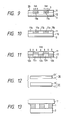
- an image receiving medium 7 is laminated on the image forming layer 1 in which the polymer image has been formed, followed by heating.
- the heat-diffusible coloring matter the image forming medium previously contains is diffusion-transferred to the image receiving medium 7, corresponding with the latent image, and thus an image comprised of the heat-diffusible coloring matter is formed on the image receiving medium (Transfer step).
- the image formation according to the above transfer step in which the amount of transfer of the heat-diffusible coloring matter can be controlled according to the degree of polymerization (the amount of transfer of the heat-diffusible coloring matter decreases as the degree of polymerization increases), makes it possible to readily obtain an image with density gradation.
- the image receiving medium 7 is, as shown in Fig. 14, laminated on the polymerizing layer 12 after the step of polymerization has been completed (provided that, in the instance of the image forming medium shown in Fig. 9, after the step of polymerization has been completed and the photosensitive layer 11 has been peeled), followed by heating to an appropriate degree.
- the heat-diffusible coloring matter present at the part 12a having a low degree of polymerization in the polymerizing layer 12 is selectively diffusion-transferred, since the heat-diffusibility of the heat-diffusible coloring matter present at the part 12b having a high degree of polymerization is suppressed in the polymerizing layer 12, compared with the heat- diffusible coloring matter present at the part 12a having a low degree of polymerization.
- the polymerizing layer 12 and image receiving medium 7 are directly laminated after the photosensitive layer 11 has been removed, but it is also possible to carry out the thermal transfer of the heat-diffusible coloring matter in the state that the photosensitive layer 11 is provided.
- the binder used in the photosensitive layer 11 should be a binder that enables easy peeling of the photosensitive layer 11 from the polymerizing layer 12.
- the mechanism by which the diffusibility of the heat-diffusible coloring matter in the polymerized area 12b is that the molecular chain of the polymer can be loosened with difficulty even when the polymerized area 12b is heated, as result of the polymerization of the polymerizable polymer precursor or, when a polyfunctional polymerizable polymer precursor is contained, as a result of the crosslinking thereof, and thus the heat-diffusible coloring matter is suppresses from being diffused.
- the heat- diffusible coloring matter may not be incorporated in the image forming layer 1 or polymerizing layer 12, and instead a coloring material layer containing the heat-diffusible coloring matter may be provided between the image forming layer 1 and support 2 or between the polymerizing layer 12 ad support 2.
- the image attributable to the heat-diffusible coloring matter can also be thereby formed in the same way as the previously described.
- an image forming method in which a coloring matter is transferred using a dry, silver salt type image forming medium is a method utilizing a reducing agent to which the function of generating a coloring matter is imparted.
- This known method involves the disadvantage that the resulting image has so poor light-resistance and storage stability that laminating must be carried out or an ultraviolet absorbent must be used in a large amount.
- the reducing agent and the coloring matter are separate components, and hence the coloring matter can be arbitrarily selected, so that an image having light-resistance, storage stability and good tone can be obtained.
- the heat-diffusible coloring matter may be contained in an amount of from 5 to 200 parts by weight, and more preferably from 10 to 100 parts by weight, based on 100 parts by weight of the total sum of the silver halide, organic silver salt, reducing agent, polymerizable polymer precursor, photopolymerization initiator and the binder optionally contained.
- the heat-diffusible coloring matter may suitably be contained in an amount of from 5 to 60 % by weight based on the polymerizing layer 12. In the instance where the coloring material layer is provided, the heat-diffusible coloring matter may preferably be contained in an amount not less than 5 % based on the coloring material layer.
- the coloring material layer can also be constituted of only the heat-diffusible coloring matter.
- the heat-diffusible coloring matter used in the present invention includes, for example, monoazo dyes, thiazole dyes, anthraquinone dyes, triallylmethane dyes, rhodamine dyes, and naphthol dyes.
- the heat-diffusible coloring matter in general, has a larger heat-diffusibility as the molecular weight becomes smaller, and also has a smaller heat-diffusibility as the dye has more polar groups as exemplified by a carboxyl group, an amino group, a hydroxyl group, a nitro group and a sulfone group.
- coloring matters having the desired heat-diffusibility may be appropriately selected on the basis of the molecular weight and polar groups, depending on the degree of polymerization or crosslink density and heating conditions in the image forming medium of the present invention.
- the image receiving medium used in the step of transferring the heat-diffusible coloring matter there are no particular limitations on the image receiving medium used in the step of transferring the heat-diffusible coloring matter, so long as it enables good transfer of the heat-diffusible coloring matter and is capable of forming a good image. It may be a plain paper, but preferably be comprised of a substrate provided thereon with an image receiving layer so that the heat-diffusible coloring matter may be transferred to this image receiving layer.
- various materials can be used, as exemplified by polyester resins, polycarbonate resins, polyvinyl acetate resins, polyurethane resins, polyamide resins, polycaprolactam resins, adn polyvinyl chloride resins.
- Preferred values for the heating temperature in the transfer step may vary depending on various conditions such as the type of the heat-diffusible coloring matter and the degree of polymerization of the polymer, but may range from 80 to 250°C, and preferably from 80 to 200°C.
- te image forming medium may be peeled from the image receiving medium.
- the heat-diffusible coloring matter is transferred to the image receiving medium 7 and an image 8 can be obtained on an image receiving layer 7b on a substrate 7a as shown in Fig. 16.
- the image obtained through the transfer step is an image having a superior contrast to give an image having a superior brightness and chroma.
- a plurality of image forming mediums containing heat-diffusible coloring matters having colors different from each other as, e.g., yellow, magneta, cyan, and also black, may be used to form images with the respective colors, overlapping on a single image receiving medium, whereby an image with multiple colors can also be formed.
- Such an image with multiple colors can also be formed by an image forming medium (or a polymerization material) comprising a single support having thereon an image receiving layer (or a polymerizing layer, or a coloring material layer) containing heat-diffusible coloring matters with different colors (for example, yellow, magenta, cyan, and also black) in the state separated into regions for the respective colors.
- an image forming medium or a polymerization material
- the heat-diffusible coloring matters may be successively transferred from the required color regions and the images with the respective colors may be overlapped each other, so that the image with multiple colors can be formed.
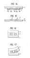
- the polymer image can also be separated to the image receiving medium side and support side, utilizing the difference in adhesion between the area sufficiently polymerized and the area at which no polymerization has proceeded (Peeling-apart).
- an image forming medium comprising an image receiving medium 9 laminated on an image forming layer 1 is used, where, after the step of polymerization has been completed (Fig. 16), the image receiving medium 9 is peeled from the image forming medium (Fig. 17).
- the polymer image is separated at the area sufficiently polymerized and the area at which no polymerization has proceeded, and thus a positive image and a negative image can be obtained.
- the area sufficiently polymerized and the area at which no polymerization has proceeded are separated when the photosensitive material 30 is peeled from the polymerization material 31.
- the image receiving medium 9 used in the peeling-apart includes, for example, art paper, coated paper, films, and metallic foil.
- heating may not necessarily be required, but the image forming medium and image receiving medium may preferably be heated to about 40°C to about 150°C to carry out the transfer.
- the transfer may preferably be carried out under a pressure of from 0.5 kg/cm2 to 400 kg/cm2, and preferably from 1 kg/cm2 to 150 kg/cm2.
- the method of the present invention can be said to be a superior method to the methods disclosed in these, on account of the photosensitivity, the photosensitivity wavelength region, and the fact that image processing is possible.
- the polymer image may further be colored by selectively adhering a powder such as toner, or an ink, to the polymer image, utilizing the difference in adhesion or the difference in hydrophilic nature (or hydrophobic nature) between the polymerized area and unpolymerized area of the polymer image.
- the powder such as toner, or the ink, adhered to the polymer image may further be transferred to an image receiving medium such as paper.
- the unpolymerized area of the polymer image may also be removed by etching to give an image comprised of the polymerized area.
- a dispersion having the following composition was prepared in a darkroom.
- Behenic acid 2.5 parts Silver behenate 4.5 parts Silver bromide 0.7 part Polyvinyl butyral (S-LEC BL-1; a product of Sekisui Chemical Co., Ltd.) 10.0 parts Trimethylolpropane triacrylate (NK Ester A-TMPT; a product of Shin-Nakamura Chemical Co., Ltd.) 10.0 parts Ethyl 4-dimethylaminobenzoate (KAYACURE EPA; a product of Nippon Kayaku Co., Ltd.) 0.6 part 2,4-Diethylthioxanthone (KAYACURE DETX; a product of Nippon Kayaku Co., Ltd.) 0.4 part 4,4′-Methylenebis(2,6-di-t-butylphenol) 3.2 parts Phthalazinone 0.8 part Xylene 60 parts n-Butanol 60 parts
- PTA film polyethylene terephthalate film
- PVA layer polyvinyl alcohol layer
- the image forming medium of the present Example on which a mask was laid overlapping, was further imagewise exposed to light for 10 seconds through a filter that does not pass the light of 400 nm or less, using an ultra-high-pressure mercury lamp having an electric power of 500 W, with a distance of 60 cm from the medium.
- the mask was thereafter removed, and the medium was heated for 16 seconds using a heat-developing machine regulated at 125°C.
- the filter was removed, and the polymerization exposure was carried out for 5 seconds using the above ultra-high-pressure mercury lamp with a distance of 60 cm from the medium, to form a polymer image.
- the PVA layer was removed by washing with water, followed by etching with ethanol.
- the polymerized area of the polymer image remained on the PET film.
- a dispersion having the following composition was prepared in a darkroom. Palmitic acid 1.6 parts Behenic acid 0.4 part Silver behenate 4.0 parts Silver iodobromide 0.9 part Methyl methacrylate/styrene (8/2) copolymer 12.0 parts Trimethylolpropane triacrylate (NK Ester A-TMPT; a product of Shin-Nakamura Chemical Co., Ltd.) 4.0 parts Dipentaerythritol hexaacrylate (KAYARD DPHA; a product of Nippon Kayaku Co., Ltd.) 6.5 parts p-Diethylaminobenzonitrile 0.2 part Benzyl dimethyl ketal (Irgacure 651; a product of Ciba Geigy Corp.) 0.3 part ⁇ -(3,5-di-t-butyl-4-hydroxyphenyl)- ⁇ -phenylethane 2.8 parts Phthalazinone 0.7 part Toluene 80 parts
- This dispersion was coated on a PET film so as to give a dried film thickness of 8 ⁇ m. Subsequently, the resulting coating was laminated on an anodized aluminum sheet to obtain an image forming medium of the present invention.
- the image forming medium of the present Example was further imagewise exposed to light in the same manner as Example 1. Thereafter, the medium was heated for 8 seconds using a heat-developing machine regulated at 130°C.
- the filter was removed, and the polymerization exposure was carried out for 10 seconds using the same ultra-high-pressure mercury lamp as used in the imagewise exposure, with a distance of 60 cm from the medium, to form a polymer image.
- the PET laminate film was removed, followed by etching with an ethanol/acetone mixed solution.
- the polymerized area of the polymer image remained on the aluminum sheet film.
- a dispersion having the following composition was prepared in a darkroom.
- Behenic acid 2.5 parts Silver behenate 4.5 parts Silver bromide 0.7 part Polymethyl methacrylate (Dianal BR-100; a product of Mitsubishi Rayon Co., Ltd.) 10.0 parts Dipentaerythritol hexaacrylate (KAYARD DPHA; a product of Nippon Kayaku Co., Ltd.) 10.0 parts Ethyl 4-dimethylaminobenzoate (KAYACURE EPA, a product of Nippon Kayaku Co., Ltd.) 0.6 part Phthalazinone 0.8 part 2,4-Diethylthioxanthone (KAYACURE DETX; a product of Nippon Kayaku Co., Ltd.) 0.4 part 4,4′-Methylenebis(2,6-di-t-butylphenol) 4.2 parts MS Magenta VP (a product of Mitsui Toatsu Chemicals Inc.) 2.0 parts Toluene 80 parts i
- This dispersion was coated on a PET film so as to give a dried film thickness of 5 ⁇ m. Subsequently, on the resulting coating, a PVA layer was further formed by coating to obtain an image forming medium of the present invention.
- the image forming medium of the present Example was further imagewise exposed to light and subjected to the heat development in the same manner as Example 1.
- the filter was removed, and, while heating the medium at 80°C, the polymerization exposure was carried out for 30 seconds using the same ultra-high-pressure mercury lamp as used in the imagewise exposure, with a distance of 60 cm from the medium, to form a polymer image.
- the PVA layer was removed by washing with water, and then the exposed surface of the image forming medium and an image receiving paper coated with polyester resin were laid overlapping each other, which were then passed through a 100°C transfer roller. Thereafter the image receiving paper was peeled from the image forming medium. As a result, a sharp red image corresponding with the imagewise exposed area was formed on the image receiving paper.
- Example 1 was repeated to prepare an image forming medium of the present invention, except that 2.5 parts of 4,4′-methylenebis(2-t-butyl-6-methylphenol) was used in place of the reducing agent 4,4′-methylenebis(2,6-di-t-butylphenol) in Example 1.
- the image forming medium of the present invention was further subjected to formation of a polymer image in the same manner as Example 1, followed by etching with ethanol. As a result, the polymerized area of the polymer image remained on the PET film. In the present Example, it was also possible to obtain the image by etching, even when the exposure time for the polymerization exposure was varied within the range of from 3 seconds to 15 seconds.
- the resulting dispersion was coated on a PET film so as to give a dried film thickness of 5 ⁇ m.
- a PVA layer was further formed by coating to obtain an image forming medium of the present invention.
- image writing was carried out with a He-Ne laser (wavelength: 633 nm; output: 5 mW), using a drum-scanning laser beam printer (LBPP, manufactured by Abe Sekkei). Thereafter, the heat development and polymerization exposure were carried out in the same manner as Example 1. Subsequently, the PVA layer was removed by washing with water, followed by etching with ethanol. As a result, there was obtained an image corresponding with the irradiation with laser beams.
- LBPP drum-scanning laser beam printer
- Solution B ws coated using an applicator so as to give a dried film thickness of 2 ⁇ m. A polymerizing layer was thus provided.
- Solution A was coated using an applicator so as to give a dried film thickness of 2 ⁇ m.
- a photosensitive layer was thus provided.
- a 3 ⁇ m thick PVA layer was further provided to obtain an image forming medium of the present invention.
- a mask was fitted to the PVA layer of the image forming medium of the present Example, and the resulting medium was imagewise exposed to light to form a latent image.
- Used as a light source was a 10 W fluorescent lamp having a peak wavelength at 390 nm, and the exposure was carried out for 1 second with a distance, of 5 cm from the image forming medium.
- the mask was thereafter removed, and the medium was heated for 8 seconds using a heat-developing machine regulated at 110°C. At this time, the optical density at the absorption peak of the photosensitive layer was 3.30.
- the resulting image forming medium was placed on a hot plate heated to 60°C, which was irradiated for 60 seconds with light of a 10 W fluorescent lamp having a fluorescent peak at 390 nm, with a distance from 5 cm from the medium, to form a polymer image.
- the PVA film and photosensitive layer were removed.
- an image receiving medium a synthetic paper on which an image receiving layer was formed with polyester resin
- the polymerizing layer and image receiving layer were laid overlapping each other, followed by the heating from the image forming medium side under conditions of 120°C and 10 seconds.
- the dye was diffusion-transferred from the polymerizing layer to the image receiving layer, and a sharp red image corresponding with the imagewise exposed area was obtained to the image receiving paper.
- Example 6 was repeated to prepare an image forming medium of the present invention, except that 5 parts of silver benzotriazole and 2 parts of guanidine trichloromethylacetate were used in place of the silver behenate in Example 6.
- the medium was imagewise exposed to light in the same manner as Example 6, followed by heating for 20 seconds using a heat-developing machine regulated at 120°C. Subsequently, the polymerization exposure and the subsequent procedures were carried out in the same manner as Example 6. As a result, a sharp red image was obtained on the image receiving paper.
- Solution D was coated using an applicator so as to give a dried film thickness of 2 ⁇ m to form a coloring material layer.
- Solution E was further coated on this coloring material layer so as to give a dried film thickness of 2 ⁇ m to provide a polymerizing layer.
- Solution C was coated using an applicator so as to give a dried film thickness of 2 ⁇ m to provide a photosensitive layer.
- a PVA layer with a thickness of 3 ⁇ m was further provided. An image forming medium of the present invention was thus prepared.
- a mask was fitted to the PVA layer of the image forming medium of the present Example, and the resulting medium was imagewise exposed to light to form a latent image.
- Used as a light source was a 10 W fluorescent lamp having a peak wavelength at 420 nm, and the exposure was carried out for 20 msec with a distance of 5 cm from the image forming medium.
- the mask was thereafter removed, and the medium was heated for 20 seconds using a heat-developing machine regulated at 120°C.
- the resulting image forming medium was irradiated on its whole surface for 5 seconds with light of a 10 W fluorescent lamp having a fluorescent peak at 335 nm, with a distance from 3 cm from the medium, to form a polymer image.
- a mask was fitted to the image forming medium thus prepared, and the resulting medium was imagewise exposed to light to form a latent image.
- Used as a light source was a 10 W fluorescent lamp having a fluorescent peak at 390 nm, and the exposure was carried out for 2 seconds with a distance of 5 cm from the image forming medium.
- the mask was thereafter removed, and the medium was heated for 10 seconds using a heat-developing machine regulated at 130°C.
- the above image forming medium was further placed on a hot plate heated to 60°C, which was irradiated for 20 seconds with light of a 10 W fluorescent lamp having a fluorescent peak at 380 nm, with a distance from 5 cm from the image forming medium, to form a polymer image.
- Film B was peeled while the above image forming medium was being passed through rollers heated at 60° under a pressure of 25 kg/cm2. As a result, a red image was formed on the film.
- Example 6 Using this image forming medium, the image formation was carried out in the same manner as Example 6. As a result, a red image was obtained on the image receiving paper. The resulting dye image had a lower maximum optical density for red than that of the image obtained in Example 6, but caused no practical problems. The optical density at the absorption peak of the photosensitive layer was 3.36 after the imagewise exposure and heating were completed.
- a dispersion having the following composition was prepared in a darkroom.
- Behenic acid 2.5 parts Silver behenate 4.5 parts Silver bromide 0.7 part Polyvinyl butyral (S-LEC BL-2; a product of Sekisui Chemical Co., Ltd.) 10.0 parts Trimethylolpropane triacrylate (NK Ester A-TMPT; a product of Shin-Nakamura Chemical Co., Ltd.) 10.0 parts Phthalazinone 0.6 part Ethyl 4-dimethylaminobenzoate 0.6 part 3,3′-Carbonylbis(7-diethylaminocumarine) 0.6 part Camphorquinone 0.6 part 4,4′-Methylenebis(2-methyl-1-naphthol) 3.4 parts Xylene 60 parts n-Butanol 60 parts
- This dispersion was coated on a PET film so as to give a dried film thickness of 5 ⁇ m. Subsequently, on the resulting coating, a PVA layer was further formed by coating to obtain an image forming medium of the present invention.
- the image forming medium of the present Example on which a mask was laid overlapping, was further imagewise exposed to light for 2 seconds through a filter that transmits the light of 390 nm but does not pass the light of 440 nm or more, using an ultra-high-pressure mercury lamp having an electric power of 500 W, with a distance of 60 cm from the medium.
- the mask was thereafter removed, and the medium was heated for 16 seconds using a heat-developing machine regulated at 110°C.
- the filter was removed, and the polymerization exposure was carried out for 10 seconds using the above ultra-high-pressure mercury lamp with a distance of 60 cm from the medium, to form a polymer image.
- the PVA layer was removed by washing with water, followed by etching with ethanol.
- the polymerized area of the polymer image remained on the PET film.
- Example 11 was repeated to obtain an image forming medium of the present invention, except that 3.4 parts of 4,4′-methylenebis(2-methyl-1-naphthol) in Example 11 was replaced with 3.6 parts of 4,4′-methylenebis(2-t-butyl-1-naphthol).
- the image forming medium of the present invention was further subjected to formation of a polymer image in the same manner as Example 11, followed by etching with ethanol. As a result, the polymerized area of the polymer image remained on the PET film. In the present Example, it was also possible to obtain the image by etching, even when the exposure time for the polymerization exposure was varied within the range of from 2 seconds to 20 seconds.
- Example 11 was repeated to obtain an image forming medium of the present invention, except that 3.4 parts of 4,4′-methylenebis(2-methyl-1-naphthol) in Example 11 was replaced with 4.9 parts of 4,4′-methylenebis(2-benzyl-1-naphthol).
- the image forming medium of the present Example was further imagewise exposed to light in the same manner as Example 11, and hereafter heated for 16 seconds using a heat-developing machine regulated at 120°C.
- the resulting image forming medium was thereafter subjected to polymerization exposure in the same manner as Example 11, followed by washing with water and then etching with ethanol.
- the polymerized area of the polymer image remained on the PET film.
- a polymerizing layer was formed by coating on a PET film so as to give a dried film thickness of 2 ⁇ m to provide the polymerization material as shown in Fig. 12.
- a photosensitive composition having the following composition was prepared.
- Behenic acid 2.5 parts
- Silver behenate 4.5 parts
- Silver bromide 0.9 part
- Polyvinyl butyral 10.0 parts
- Phthalazinone 1.2 parts
- 4,4′-Methylenebis(2-methyl-1-naphthol) 3.4 parts
- Xylene 60 parts
- n-Butanol 60 parts
- the above photosensitive material was further imagewise exposed to light in the same manner as Example 11, and then heated for 10 second using a heat-developing machine regulated at 115°C.
- the photosensitive material and polymerization material were laid overlapping in the manner that the PVA layer and polymerizing layer may face each other, followed by polymerization exposure for 20 seconds from the photosensitive material side, using the same light source as Example 11, while heating with a hot plate of 80°C.
- the photosensitive material was peeled, and thereafter the polymerization material was etched with methyl ethyl ketone. As a result, the polymerized area of the polymer image remained on the PET film.
- an image receiving paper coated with polyester resin was also laid overlapping on the polymer image on the polymerization material, and these were passed through heat rollers with a nip width of 4 mm, regulated at 130°C, and at a speed of 1.3 sec/cm. As a result, a cyan image corresponding with the imagewise exposure was formed on the image receiving paper.
- a dispersion having the following composition was prepared in a darkroom.
- Behenic acid 2.5 parts
- Silver behenate 4.5 parts
- Silver iodobromide 0.7 part
- Polymethyl methacrylate 10.0 parts
- Trimethylolpropane triacrylate 10.0 parts
- 3,3′-Carbonylbis(7-diethylaminocumarine) 0.6 part
- Ethyl 4-dimethylaminobenzoate 0.6 part 2-t-Butyl-4-(4-hydroxyphenyl)methyl-1-naphthol 2.9 parts
- a homomixer was used to carry out dispersion, and the resulting dispersion was coated on a support comprising a PET film so as to give a dried film thickness of 6 ⁇ m to prepare an image forming medium of the present invention.
- an anodized aluminum sheet was laminated, and a mask was laid overlapping on the PET film.
- the resulting medium was imagewise exposed to light for 1 second using a 10 W fluorescent lamp. Thereafter, the mask was removed, followed by heating using a heat-developing machine under conditions of 115°C for 16 seconds.
- the image forming medium was thereafter subjected to polymerization exposure for 5 seconds using ultraviolet light that gave 8.0 mW/cm2 at the surface of the image forming medium.
- the PET film on the above image forming medium was peeled, followed by etching with ethanol. As a result, the polymerized area of the polymer image remained on the support as a sharp image.
- a dispersion having the following composition was prepared in a darkroom. Palmitic acid 1.6 parts Behenic acid 0.4 part Silver behenate 4.0 parts Silver bromide 0.9 part Methyl methacrylate/styrene (8/2) copolymer 12.0 parts Trimethylolpropane triacrylate 4.0 parts Dipentaerythritol hexaacrylate 6.5 parts 3,3′-Carbonylbis(7-diethylaminocumarine) 0.5 part p-Diethylaminobenzonitrile 0.2 part 2-Methyl-4-(3,5-dichloro-4-hydroxyphenyl)methyl-1-naphthol 3.2 parts Toluene 80.0 parts i-Propanol 40.0 parts
- This dispersion was coated on a support comprising a PET film to give a dried film thickness of 8 ⁇ m.
- An image forming medium of the present invention was thus prepared.
- Example 15 On the above image forming medium, an aluminum sheet was laminated, followed by etching in the same manner as Example 15. As a result, the polymerized area of the polymer image remained on the support as a sharp image.
- a dispersion having the following composition was prepared in a darkroom.
- Behenic acid 2.5 parts Silver behenate 4.5 parts Silver bromide 0.7 part
- Polyvinyl butyral 0.4 part
- Polymethyl methacrylate 10.0 parts
- 2,4-Bis[2-(acryloxy)ethoxycarbamoyl]toluene 4.0 parts
- Pentaethythritol triacrylate 8.0 parts 3,3′-Carbonylbis(7-pyrrolidinocumarine) 0.7 part
- Ethyl 4-dimethylaminobenzoate 0.4 part
- Phthalazinone 0.8 part 2-Methyl-4-(3,5-dimethyl-4-hydroxyphenyl)methyl-1-naphthol 3.1 parts
- Toluene 80 parts i-Propanol 40 parts
- the dispersion with the above composition was coated on a support comprising a PET film so as to give a dried film thickness of 5 ⁇ m to prepare an image forming medium of the present invention.
- a polyurethane layer was provided as a subbing layer of the image forming layer.
- Example 15 On the image forming layer of the above image forming medium of the present invention, a polyethylene film was laminated, followed by the same manner as Example 15. As a result, as sharp image comprised of the polymerized area of the polymer image was obtained on the support.
- Example 15 was repeated to prepare an image forming medium of the present invention, except that 2.9 parts of 2-t-butyl-4-(4-hydroxyphenyl)methyl-1-naphthol was replace with 2.9 parts of 2-methyl-4-(4-dimethylaminophenyl)methyl-1-naphthol.
- This image forming medium was subjected to the same manner as Example 15. As a result, the polymerized area of the polymer image remained on the support as a sharp image.
- Solution H was coated so as to give a dried film thickness of 2 ⁇ m to form a coloring material layer, and then Solution I was coated thereon so as to give a dried film thickness of 4 ⁇ m to form a polymerizing layer.
- Solution J was further coated so as to give a dried film thickness of 5 ⁇ m to form a photosensitive layer, and, finally on the photosensitive layer, a PVA layer with a thickness of 2 ⁇ m was provided. An image forming method of the present invention was thus obtained.
- a mask was laid overlapping on this image forming medium, and the resulting medium was imagewise exposed to light for 10 seconds using light that gave 900 lux at the part of the image forming layer, and subsequently heated for 30 seconds using a heat-developing machine regulated at 125°C.
- this image forming medium was subjected to polymerization exposure for 10 seconds using a fluorescent lamp having a peak wavelength at 380 nm, with a distance of 3 cm from the image forming medium.
- Example 6 As a final step, the PVA layer and photosensitive layer were removed and an image was formed on an image receiving paper in the same manner as Example 6. As a result, an image corresponding with the imagewise exposed area was obtainable on the image receiving paper.
- the image obtained in the present Example showed a lower maximum optical density compared with Example 6, but there was no practical problems.
- the image forming medium was subjected to imagewise exposure, heat development and polymerization exposure, followed by etching with ethanol in the same manner as Example 6.
- an image comprised of the polymerized area of the polymer image was obtainable on the PET film.
- the above conditions for the polymerization exposure were also varied.
- Example 11 was repeated to prepare an image forming medium of the present invention, except that in Example 11, 3.4 parts of 4,4′-methylenebis(2-methyl-1-naphthol) was replaced with 1.7 parts of 2-amino-5-diethylaminotoluene and 4.6 parts of benzoylaceto-o-chloroanilide, and the image formation was carried out in the same way. As a result, a sharp image of polymer was obtained.
- Yellow coating solution Polybutyl methacrylate (Dianal BR-79; Mitsubishi Rayon Co. Ltd.) 7.0 parts MS-Yellow-VP (a dye of Mistui Toatsu Chemicals, Inc.) 1.0 part Methyl ethyl ketone 63 parts Magenta coating solution: Polybutyl methacrylate (Dianal BR-79; Mitsubishi Rayon Co. Ltd.) 7.0 parts MS-Magenta-VP (a dye of Mistui Toatsu Chemicals, Inc.) 0.6 part Methyl ethyl ketone 63 parts Cyan coating solution: Polybutyl methacrylate (Dianal BR-79; Mitsubishi Rayon Co. Ltd.) 7.0 parts MS-Cyan-VP (a dye of Mistui Toatsu Chemicals, Inc.) 0.95 part Methyl ethyl ketone 63 parts
- the yellow coating solution, magenta coating solution and cyan coating solution each having the above composition were made up. On a 22 ⁇ m thick PET film having been subjected to anchoring, these solutions were coated dividedly for each color region, using a three-color gravure coater, to form a coloring material layer.
- the coloring material layer had a dried film thickness of 2 ⁇ m.
- This emulsion was coated on the above coloring material layer so as to give a dried film thickness of 5 ⁇ m to form a photosensitive polymerizing layer.
- a protective layer with a dried film thickness of 2 ⁇ m was further provided thereon by use of polyvinyl butyral to obtain an image forming medium of the present invention.
- image writing was carried out with a He-Ne laser (output: 5 mW), using a drum-scanning laser beam printer (manufactured by Abe Sekkei).
- this image forming medium was heated under conditions of 120°C and 20 seconds, and thereafter exposed to light for 40 seconds using a fluorescent lamp having an electric power of 10 W and a fluorescent peak at 390 nm, with a distance of 1 cm from the medium.
- am image receiving paper on which an image receiving layer was previously formed and the above image forming medium were laminated, followed by heating under conditions of 130°C and 10 seconds.
- a yellow image excellent in both the brightness and chroma corresponding with the imagewise exposure, was formed on the image receiving paper.
- the full-color image thus obtained was an image having excellent brightness and chroma.
- the cyan coating solution used in Example 21 was coated on a PET film so as to give a dried film thickness of 3 ⁇ m to form a coloring material layer.
- Solution L was coated so as to give a dried film thickness of 4 ⁇ m to form a polymerizing layer.
- Solution M was further coated so as to give a dried film thickness of 4 ⁇ m to form a photosensitive layer.
- an ethanol solution of polyvinyl butyral was coated with a film thickness of 2 ⁇ m to form a protective layer.
- This image forming medium was imagewise exposed to light for 10 seconds using a tungsten lamp that gave an illumination of 900 lux at the surface of the medium, followed by heating for 20 seconds using a heat-developing machine regulated at 120°C. Subsequently, the resulting medium was exposed to light for 30 seconds using a fluorescent lamp having an electric power 3 of 10 W and a fluorescent peak at 380 nm, with a distance of 1 cm from the medium. Finally, on the resulting image forming medium, an image receiving paper having thereon an image receiving layer comprising polyester resin was laid overlapping, followed by heating at 130°C for 10 seconds. As a result, a cyan image was formed on the image receiving paper.
- This emulsion was coated on a PET film so as to give a dried film thickness of 5 ⁇ m to form an image forming layer.
- a PVA layer with a dried film thickness of 2 ⁇ m was further provided to prepare an image forming medium of the present invention.
- This image forming medium was imagewise exposed to light for 2 seconds through a filter that does not pass the light of 440 nm or more, using an ultra-high-pressure mercury lamp having an electric power of 500 W, with a distance of 60 cm from the medium.
- the medium was subsequently heated for 16 seconds using a heat-developing machine regulated at 115°C.
- the filter was thereafter removed, and the resulting medium was subjected to polymerization exposure for 5 seconds using the ultra-high-pressure mercury lamp with a distance of 60 cm from the medium.
- the PVA layer was removed by washing wit water, and the resulting medium was etched with ethanol. As a result, a polymer image remained on the PET film.
- Example 1 was repeated to prepare an image forming medium, except that 2.6 parts of a reducing agent 2,2′-methylenebis(4-methyl-6-t-butylphenol) was used in place of 3.2 parts of the reducing agent 4,4′-methylenebis(2,6-di-t-butylphenol) in Example 1.
- 2,2′-methylenebis(4-methyl-6-t-butylphenol) was used in place of 3.2 parts of the reducing agent 4,4′-methylenebis(2,6-di-t-butylphenol) in Example 1.
- the above image forming medium was imagewise exposed to light in the same manner as Example 1, followed by heating for 10 seconds using a heat-developing machine regulated at 115°C. As a result, a black silver image was formed at the imagewise exposed area. In respect of the imagewise exposed area of this image forming medium, the light-absorption characteristics were measured to find that substantially flat absorption was seen. The optical density at 380 nm was 1.2. Conditions for the heat-development were varied, but no changes were seen in the flat absorption.
- the above image forming medium was exposed to imagewise exposure, heat-development and polymerization exposure in the same manner as Example 1, followed by etching.
- the image forming layer was entirely dissolved out when the exposure time for the polymerization exposure was 2 seconds or less, and the image forming layer was not dissolved out when the time was longer than 2 seconds. Thus, no image was obtainable.
- Example 11 was repeated to prepare an image forming medium, except that 0.6 part of 3,3′-carbonylbis(7-diethylaminocumarine) and 0.6 part of camphorquinone in Example 11 were replaced with 0.5 part of 2,4-dichlorothioxanthone.
- f( ⁇ ) and g( ⁇ ) were measured according to the measuring method as previously described, to reveal that the absorption peak wavelength of f( ⁇ ) was greatly deviated from the absorption peak wavelength of g( ⁇ ).
- This image forming medium was subjected to the image formation in the same manner as Example 11, but there was obtained no sharp image.
- Example 1 was repeated to prepare an image forming medium, except that 0.4 part of the photopolymerization initiator 2,4-diethylthioxanthone and 0.6 parts of ethyl 4-dimethylaminobenzoate in Example 1 were replaced with 0.7 part of 3,3′-carbonylbis(7-diethylaminocumarine) and 0.5 part of 2,4,6- tris(trichloromethyl)-S-triazine.
- f( ⁇ ) and g( ⁇ ) were measured according to the measuring method as previously described, to reveal that the absorption peak wavelength of f( ⁇ ) was greatly deviated from the absorption peak wavelength of g( ⁇ ).
- This image forming medium was subjected to the image formation in the same manner as Example 1, but there was obtained no sharp image.
- An image forming method comprises; subjecting an image formig medium containing at least a photosensitive silver halide, an organic silver salt, a reducing agent, a polymerizable polymer precursor and a photopolymerization initiator, to imagewise exposure, followed by heating to produce a light-absorbing organic compound in said image forming medium; and subjecting said image forming medium in which said light-absorbing organic compound has been produced, to polymerization exposure to cause said polymerizable polymer precursor to polymerize; where the light-absorption characteristics of said light-absorbing organic compound are utilized to suppress the polymerization of said polymerizable polymer precursor at the area at which said light-absorbing organic compound has been produced.
Applications Claiming Priority (10)
| Application Number | Priority Date | Filing Date | Title |
|---|---|---|---|
| JP25017288 | 1988-10-04 | ||
| JP250172/88 | 1988-10-04 | ||
| JP250174/88 | 1988-10-04 | ||
| JP25017488 | 1988-10-04 | ||
| JP25017688 | 1988-10-04 | ||
| JP250176/88 | 1988-10-04 | ||
| JP130164/89 | 1989-05-25 | ||
| JP13016489 | 1989-05-25 | ||
| JP182033/89 | 1989-07-13 | ||
| JP18203389 | 1989-07-13 |
Publications (3)
| Publication Number | Publication Date |
|---|---|
| EP0363790A2 true EP0363790A2 (fr) | 1990-04-18 |
| EP0363790A3 EP0363790A3 (en) | 1990-05-09 |
| EP0363790B1 EP0363790B1 (fr) | 1995-05-31 |
Family
ID=27527229
Family Applications (1)
| Application Number | Title | Priority Date | Filing Date |
|---|---|---|---|
| EP19890118323 Expired - Lifetime EP0363790B1 (fr) | 1988-10-04 | 1989-10-03 | Méthode pour la formation d'image et matériel |
Country Status (4)
| Country | Link |
|---|---|
| EP (1) | EP0363790B1 (fr) |
| AU (1) | AU631145B2 (fr) |
| CA (1) | CA2000070C (fr) |
| DE (1) | DE68922889T2 (fr) |
Cited By (6)
| Publication number | Priority date | Publication date | Assignee | Title |
|---|---|---|---|---|
| EP0453317A2 (fr) * | 1990-04-20 | 1991-10-23 | Canon Kabushiki Kaisha | Moyen pour former des images |
| EP0461621A2 (fr) * | 1990-06-12 | 1991-12-18 | Canon Kabushiki Kaisha | Méthode pour l'enregistrement de l'image |
| EP0505155A1 (fr) * | 1991-03-22 | 1992-09-23 | Canon Kabushiki Kaisha | Masque thermo développable |
| WO2016096719A1 (fr) * | 2014-12-18 | 2016-06-23 | Agfa Graphics Nv | Composition durcissable par rayonnement |
| US20160303831A1 (en) * | 2013-12-12 | 2016-10-20 | Agfa Graphics Nv | Laminated safety glass |
| WO2017116372A1 (fr) * | 2015-12-31 | 2017-07-06 | Arsu Nergis | Procédé de préparation de films nanocomposites comprenant une nanopoarticle d'or par une technique de photopolymérisation |
Citations (9)
| Publication number | Priority date | Publication date | Assignee | Title |
|---|---|---|---|---|
| US3874947A (en) * | 1968-08-20 | 1975-04-01 | Fuji Photo Film Co Ltd | Process for the production of polymer images |
| JPS5350246A (en) * | 1976-10-20 | 1978-05-08 | Bridgestone Corp | Rubber composition having good adhesion to metal |
| DE3207064A1 (de) * | 1981-02-27 | 1982-12-23 | Fuji Photo Film Co., Ltd., Minami-Ashigara, Kanagawa | Verfahren zur bildung polymerer bilder |
| US4624910A (en) * | 1984-05-25 | 1986-11-25 | Fuji Photo Film Co., Ltd. | Image recording process |
| EP0202490A1 (fr) * | 1985-04-22 | 1986-11-26 | Fuji Photo Film Co., Ltd. | Méthode de formation d'une image de polymère et matériau d'enregistrement d'image à cet effet |
| US4649098A (en) * | 1984-09-21 | 1987-03-10 | Fuji Photo Film Co., Ltd. | Image recording process using both silver halide and vinyl monomers |
| EP0326424A2 (fr) * | 1988-01-29 | 1989-08-02 | Canon Kabushiki Kaisha | Composition photosensible, matériau photosensible et méthode pour la formation d'images |
| EP0328364A2 (fr) * | 1988-02-08 | 1989-08-16 | Canon Kabushiki Kaisha | Matériel photosensible |
| EP0330504A2 (fr) * | 1988-02-26 | 1989-08-30 | Canon Kabushiki Kaisha | Materiel photosensible et procédé pour la formation de l'image |
-
1989
- 1989-10-03 CA CA 2000070 patent/CA2000070C/fr not_active Expired - Lifetime
- 1989-10-03 EP EP19890118323 patent/EP0363790B1/fr not_active Expired - Lifetime
- 1989-10-03 DE DE1989622889 patent/DE68922889T2/de not_active Expired - Lifetime
- 1989-10-04 AU AU42584/89A patent/AU631145B2/en not_active Ceased
Patent Citations (9)
| Publication number | Priority date | Publication date | Assignee | Title |
|---|---|---|---|---|
| US3874947A (en) * | 1968-08-20 | 1975-04-01 | Fuji Photo Film Co Ltd | Process for the production of polymer images |
| JPS5350246A (en) * | 1976-10-20 | 1978-05-08 | Bridgestone Corp | Rubber composition having good adhesion to metal |
| DE3207064A1 (de) * | 1981-02-27 | 1982-12-23 | Fuji Photo Film Co., Ltd., Minami-Ashigara, Kanagawa | Verfahren zur bildung polymerer bilder |
| US4624910A (en) * | 1984-05-25 | 1986-11-25 | Fuji Photo Film Co., Ltd. | Image recording process |
| US4649098A (en) * | 1984-09-21 | 1987-03-10 | Fuji Photo Film Co., Ltd. | Image recording process using both silver halide and vinyl monomers |
| EP0202490A1 (fr) * | 1985-04-22 | 1986-11-26 | Fuji Photo Film Co., Ltd. | Méthode de formation d'une image de polymère et matériau d'enregistrement d'image à cet effet |
| EP0326424A2 (fr) * | 1988-01-29 | 1989-08-02 | Canon Kabushiki Kaisha | Composition photosensible, matériau photosensible et méthode pour la formation d'images |
| EP0328364A2 (fr) * | 1988-02-08 | 1989-08-16 | Canon Kabushiki Kaisha | Matériel photosensible |
| EP0330504A2 (fr) * | 1988-02-26 | 1989-08-30 | Canon Kabushiki Kaisha | Materiel photosensible et procédé pour la formation de l'image |
Non-Patent Citations (1)
| Title |
|---|
| PATENT ABSTRACTS OF JAPAN vol. 20, no. 4 (P-16)(568) 20 June 1980, & JP-A-53 050 246 (FUJI SHASHIN FILM K.K.) 05 October 1978, * |
Cited By (12)
| Publication number | Priority date | Publication date | Assignee | Title |
|---|---|---|---|---|
| EP0453317A2 (fr) * | 1990-04-20 | 1991-10-23 | Canon Kabushiki Kaisha | Moyen pour former des images |
| EP0453317A3 (en) * | 1990-04-20 | 1992-04-22 | Canon Kabushiki Kaisha | Image forming medium |
| EP0461621A2 (fr) * | 1990-06-12 | 1991-12-18 | Canon Kabushiki Kaisha | Méthode pour l'enregistrement de l'image |
| EP0461621A3 (en) * | 1990-06-12 | 1992-09-16 | Canon Kabushiki Kaisha | Image forming method |
| US5393638A (en) * | 1990-06-12 | 1995-02-28 | Canon Kabushiki Kaisha | Image forming method |
| EP0505155A1 (fr) * | 1991-03-22 | 1992-09-23 | Canon Kabushiki Kaisha | Masque thermo développable |
| US20160303831A1 (en) * | 2013-12-12 | 2016-10-20 | Agfa Graphics Nv | Laminated safety glass |
| US10549508B2 (en) * | 2013-12-12 | 2020-02-04 | Agfa Nv | Laminated safety glass |
| WO2016096719A1 (fr) * | 2014-12-18 | 2016-06-23 | Agfa Graphics Nv | Composition durcissable par rayonnement |
| US10752782B2 (en) | 2014-12-18 | 2020-08-25 | Agfa Nv | Radiation curable compositions |
| WO2017116372A1 (fr) * | 2015-12-31 | 2017-07-06 | Arsu Nergis | Procédé de préparation de films nanocomposites comprenant une nanopoarticle d'or par une technique de photopolymérisation |
| US10526240B2 (en) | 2015-12-31 | 2020-01-07 | Nergis Arsu | Preparation method of nanocomposite films comprising gold nanopoarticle via photopolymerization technique |
Also Published As
| Publication number | Publication date |
|---|---|
| CA2000070C (fr) | 1996-12-24 |
| DE68922889D1 (de) | 1995-07-06 |
| DE68922889T2 (de) | 1996-02-15 |
| EP0363790B1 (fr) | 1995-05-31 |
| EP0363790A3 (en) | 1990-05-09 |
| AU4258489A (en) | 1990-04-12 |
| AU631145B2 (en) | 1992-11-19 |
| CA2000070A1 (fr) | 1990-04-04 |
Similar Documents
| Publication | Publication Date | Title |
|---|---|---|
| AU619246B2 (en) | Photosensitive material comprising laminated photosensitive layer and polymerizable layer and image forming method | |
| CA1336658C (fr) | Substance photosensible, materiau photosensible et methode d'imagerie | |
| US5021321A (en) | Photosensitive member and multi-color image forming method | |
| US5171657A (en) | Light sensitive image forming medium | |
| US5415974A (en) | Photosensitive material and image forming method using same | |
| EP0363790B1 (fr) | Méthode pour la formation d'image et matériel | |
| US5187041A (en) | Image forming method and image forming apparatus | |
| US5374496A (en) | Image forming method | |
| JPH03135564A (ja) | 画像形成方法および画像形成媒体 | |
| US5393638A (en) | Image forming method | |
| EP0453317A2 (fr) | Moyen pour former des images | |
| JPH043063A (ja) | 感光体及び画像形成方法 | |
| JPH04218045A (ja) | 画像形成方法及び画像形成装置 | |
| JPH0365951A (ja) | 感光体及び画像形成方法 | |
| JPH02210353A (ja) | 画像形成媒体及び画像形成方法 | |
| JPH04226464A (ja) | 画像形成方法 | |
| JPH02309357A (ja) | 感光体と画像形成方法 | |
| JPH03252660A (ja) | 感光体および画像形成方法 | |
| JPH0456861A (ja) | 感光体および色画像形成方法 | |
| JPH0456862A (ja) | 感光体および画像形成方法 | |
| JPH03287258A (ja) | 画像形成材料および画像形成方法 | |
| JPH0389248A (ja) | 感光体および画像形成方法 | |
| JPH04113360A (ja) | 画像形成媒体及び画像形成方法 | |
| JPH03131860A (ja) | 多色画像形成方法 | |
| JPH03282469A (ja) | 感光体 |
Legal Events
| Date | Code | Title | Description |
|---|---|---|---|
| PUAI | Public reference made under article 153(3) epc to a published international application that has entered the european phase |
Free format text: ORIGINAL CODE: 0009012 |
|
| PUAL | Search report despatched |
Free format text: ORIGINAL CODE: 0009013 |
|
| AK | Designated contracting states |
Kind code of ref document: A2 Designated state(s): DE FR GB IT NL |
|
| AK | Designated contracting states |
Kind code of ref document: A3 Designated state(s): DE FR GB IT NL |
|
| RHK1 | Main classification (correction) |
Ipc: G03F 7/028 |
|
| 17P | Request for examination filed |
Effective date: 19900925 |
|
| 17Q | First examination report despatched |
Effective date: 19921029 |
|
| GRAA | (expected) grant |
Free format text: ORIGINAL CODE: 0009210 |
|
| AK | Designated contracting states |
Kind code of ref document: B1 Designated state(s): DE FR GB IT NL |
|
| REF | Corresponds to: |
Ref document number: 68922889 Country of ref document: DE Date of ref document: 19950706 |
|
| ET | Fr: translation filed | ||
| ITF | It: translation for a ep patent filed |
Owner name: PROROGA CONCESSA IN DATA: 30.10.95;SOCIETA' ITALIA |
|
| PLBE | No opposition filed within time limit |
Free format text: ORIGINAL CODE: 0009261 |
|
| STAA | Information on the status of an ep patent application or granted ep patent |
Free format text: STATUS: NO OPPOSITION FILED WITHIN TIME LIMIT |
|
| 26N | No opposition filed | ||
| REG | Reference to a national code |
Ref country code: GB Ref legal event code: IF02 |
|
| PGFP | Annual fee paid to national office [announced via postgrant information from national office to epo] |
Ref country code: NL Payment date: 20081017 Year of fee payment: 20 |
|
| PGFP | Annual fee paid to national office [announced via postgrant information from national office to epo] |
Ref country code: DE Payment date: 20081031 Year of fee payment: 20 |
|
| PGFP | Annual fee paid to national office [announced via postgrant information from national office to epo] |
Ref country code: IT Payment date: 20081020 Year of fee payment: 20 |
|
| PGFP | Annual fee paid to national office [announced via postgrant information from national office to epo] |
Ref country code: FR Payment date: 20081024 Year of fee payment: 20 |
|
| PGFP | Annual fee paid to national office [announced via postgrant information from national office to epo] |
Ref country code: GB Payment date: 20081029 Year of fee payment: 20 |
|
| REG | Reference to a national code |
Ref country code: GB Ref legal event code: PE20 Expiry date: 20091002 |
|
| NLV7 | Nl: ceased due to reaching the maximum lifetime of a patent | ||
| PG25 | Lapsed in a contracting state [announced via postgrant information from national office to epo] |
Ref country code: NL Free format text: LAPSE BECAUSE OF EXPIRATION OF PROTECTION Effective date: 20091003 |
|
| PG25 | Lapsed in a contracting state [announced via postgrant information from national office to epo] |
Ref country code: GB Free format text: LAPSE BECAUSE OF EXPIRATION OF PROTECTION Effective date: 20091002 |