EP0363350B1 - Tool holder - Google Patents
Tool holder Download PDFInfo
- Publication number
- EP0363350B1 EP0363350B1 EP19890890259 EP89890259A EP0363350B1 EP 0363350 B1 EP0363350 B1 EP 0363350B1 EP 19890890259 EP19890890259 EP 19890890259 EP 89890259 A EP89890259 A EP 89890259A EP 0363350 B1 EP0363350 B1 EP 0363350B1
- Authority
- EP
- European Patent Office
- Prior art keywords
- tool
- cut
- tools
- tool holder
- recess
- Prior art date
- Legal status (The legal status is an assumption and is not a legal conclusion. Google has not performed a legal analysis and makes no representation as to the accuracy of the status listed.)
- Expired - Lifetime
Links
- 239000006260 foam Substances 0.000 claims description 13
- 238000005520 cutting process Methods 0.000 claims description 2
- 239000000853 adhesive Substances 0.000 claims 1
- 238000003698 laser cutting Methods 0.000 description 2
- 238000004519 manufacturing process Methods 0.000 description 2
- 239000002699 waste material Substances 0.000 description 2
- 208000027418 Wounds and injury Diseases 0.000 description 1
- 230000006978 adaptation Effects 0.000 description 1
- 230000006378 damage Effects 0.000 description 1
- 230000007812 deficiency Effects 0.000 description 1
- 238000001514 detection method Methods 0.000 description 1
- 238000010586 diagram Methods 0.000 description 1
- 238000005187 foaming Methods 0.000 description 1
- 208000014674 injury Diseases 0.000 description 1
- 238000003825 pressing Methods 0.000 description 1
- 238000004064 recycling Methods 0.000 description 1
Images
Classifications
-
- B—PERFORMING OPERATIONS; TRANSPORTING
- B25—HAND TOOLS; PORTABLE POWER-DRIVEN TOOLS; MANIPULATORS
- B25H—WORKSHOP EQUIPMENT, e.g. FOR MARKING-OUT WORK; STORAGE MEANS FOR WORKSHOPS
- B25H3/00—Storage means or arrangements for workshops facilitating access to, or handling of, work tools or instruments
- B25H3/06—Trays
Definitions
- the invention relates to a tool holder, in particular for tool rooms of fire-fighting vehicles, with an elastic foam body which has at least one cutout which is adapted to the shape of a tool and optionally expanded by an additional handle recess.
- Such a tool holder is known from DE-A-3205035.
- Known tool holders consist essentially of loops, brackets, clamps and. Like., which are not only very complex to manufacture and assemble, but above all also cause rattling noises due to vibrations, involve cumbersome tool handling when inserting and removing, complicate the overview of the tools available and only with great care to maintain a certain order ensure which disadvantages are particularly significant in fire service operations.
- EP-A1-0 161 331 or FR-A-2 276 148 show, there are already tool holders made of foam or plastic bodies with recesses adapted to the tool shapes, but so far surface recesses have been formed these recesses, which require such holders for the production of expensive, complex foaming molds or pressing or deep-drawing tools and therefore remain quite limited in their area of application.
- the invention is therefore based on the object of eliminating these deficiencies and creating a tool holder of the type described above, which is characterized above all by its simple and rational producibility and by its usefulness and expediency, especially for fire service operations.
- the invention solves this problem in that a cutout which essentially follows the outer contour of the tool and extends through the entire foam body is provided as a recess, that the foam body is a self-clamping foam plate which contains cutouts which clamp the tools against falling out, and that when cut out of the cut-out plate pieces can be partly reinserted into the cut-outs as a tool base after a corresponding height division, which tool bases can also be interrupted in the area of the handle recesses.
- a foam sheet can be cut and cut individually according to the existing tools and tool rooms, for example by means of a laser cutting device, and, in order to be ready for use, only needs to be glued to the intended wall, floor or door surface of the tool room.
- this tool base allows tools of different thicknesses to be presented to the user evenly on the surface of the plate by selecting the appropriate base thickness. If the base is left out in the area of the handle recesses, there is the particular advantage that the tool held under can be gripped by hand and immediately gripped firmly and properly. Apart from this, the recycling of the cut pieces can reduce the undesired cutting waste.
- a tool fixing device preferably a Velcro strap or the like
- Velcro straps or the like are easy to operate particularly suitable.
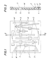
- a foam plate 1 is provided as the tool holder, which has the following cutouts 2 for receiving these tools W following the outer contour of the tools.
- These cutouts 2 are produced in adaptation to the respective requirements, for example according to a corresponding template by means of a laser cutting device, the cutouts 2 each being expanded by an additional handle recess 3.
- an arrangement diagram is created, so that when the tools are inserted into the holder, they also immediately take up the desired space and position.
- the foam sheet 1 is glued in a manner not shown to a suitable receiving surface of a tool room and is functional. If the plate pieces falling off when the cutouts 2 are cut out are inserted again into the cutouts 2 after a corresponding height division and are also glued to the receiving surface, there is an expedient tool pad 4 which prevents rattling noises or the like and through a recess 5 in the area of the handle recesses 3 the detection of the tools W facilitated.
Landscapes
- Engineering & Computer Science (AREA)
- Mechanical Engineering (AREA)
- Buffer Packaging (AREA)
Description
Die Erfindung bezieht sich auf eine Werkzeughalterung, insbesondere für Werkzeugräume von Feuerwehrfahrzeugen, mit einem elastischen Schaumstoffkörper, der zumindest eine der Form eines Werkzeuges angepaßte, gegebenenfalls durch eine zusätzliche Griffausnehmung erweiterte Aussparung aufweist.The invention relates to a tool holder, in particular for tool rooms of fire-fighting vehicles, with an elastic foam body which has at least one cutout which is adapted to the shape of a tool and optionally expanded by an additional handle recess.
Eine derartige Werkzeughaltenung ist aus der DE-A-3205035 bekannt. Bekannte Werkzeughalterungen bestehen im wesentlichen aus Schlaufen, Bügeln, Klemmen u. dgl., die nicht nur recht aufwendig herzustellen und zu montieren sind, sondern vor allem auch erschütterungsbedingte Klappergeräusche verursachen, umständliche Werkzeughandhabungen beim Einsetzen und Entnehmen mit sich bringen, den Überblick über die vorhandenen Werkzeuge erschweren und auch nur bei großer Sorgfalt das Einhalten einer gewissen Ordnung gewährleisten, welche Nachteile im Feuerwehrbetrieb besonders ins Gewicht fallen.Such a tool holder is known from DE-A-3205035. Known tool holders consist essentially of loops, brackets, clamps and. Like., which are not only very complex to manufacture and assemble, but above all also cause rattling noises due to vibrations, involve cumbersome tool handling when inserting and removing, complicate the overview of the tools available and only with great care to maintain a certain order ensure which disadvantages are particularly significant in fire service operations.
Wie die DE-A-32 05 035, die EP-A1-0 161 331 oder die FR-A-2 276 148 zeigen, gibt es auch schon Werkzeughalterungen aus Schaumstoff- oder Kunststoffkörpern mit an die Werkzeugformen angepaßten Aussparungen, doch bilden bisher Oberflächenausnehmungen diese Aussparungen, wodurch solche Halterungen zur Herstellung teure, aufwendige Ausschäum-Formen oder Preß- bzw. Tiefziehwerkzeuge verlangen und daher auch in ihrem Anwendungsbereich recht beschränkt bleiben.As DE-A-32 05 035, EP-A1-0 161 331 or FR-A-2 276 148 show, there are already tool holders made of foam or plastic bodies with recesses adapted to the tool shapes, but so far surface recesses have been formed these recesses, which require such holders for the production of expensive, complex foaming molds or pressing or deep-drawing tools and therefore remain quite limited in their area of application.
Der Erfindung liegt somit die Aufgabe zugrunde, diese Mängel zu beseitigen und eine Werkzeughalterung der eingangs geschilderten Art zu schaffen, die sich vor allem durch ihre einfache und rationelle Herstellbarkeit und durch ihre Nützlichkeit und Zweckmäßigkeit gerade für den Feuerwehrbetrieb auszeichnet.The invention is therefore based on the object of eliminating these deficiencies and creating a tool holder of the type described above, which is characterized above all by its simple and rational producibility and by its usefulness and expediency, especially for fire service operations.
Die Erfindung löst diese Aufgabe dadurch, daß als Aussparung ein im wesentlichen der Außenkontur des Werkzeuges folgender, den ganzen Schaumstoffkörper hindurchgehender Ausschnitt vorgesehen ist, daß der Schaumstoffkörper eine selbstklemmende Schaumstoffplatte ist, die Ausschnitte enthält, die die Werkzeuge herausfallsicher festklemmen, und daß die beim Ausschneiden der Ausschnitte anfallenden Plattenstücke zum Teil nach einer entsprechenden Höhenteilung wieder in die Ausschnitte als Werkzeugunterlage eingesetzt werden, welche Werkzeugunterlagen im Bereich der Griffausnehmungen auch unterbrochen sein können. So eine Schaumstoffplatte läßt sich individuell entsprechend den vorhandenen Werkzeugen und Werkzeugräumen aus- und zuschneiden, beispielsweise mittels eines Laserschneidgerätes, und braucht, um einsatzfähig zu sein, nur an der vorgesehenen Wand-, Boden- oder Türfläche des Werkzeugraumes angeklebt zu werden. Die Werkzeuge, Einrichtungen, Geräte u. dgl., die unterzubringen sind, werden dann einfach in die passenden Ausschnitte eingedrückt und sind aufgehoben. Die dem Bild der Werkzeuge entsprechenden Ausschnitte ermöglichen es, sofort die Werkzeuge lagerichtig einzusetzen und bringen zwangsweise die gewünschte Werkzeugordnung mit sich, wobei außerdem ein Blick auf die Platte zeigt, ob ein Werkzeugsatz vollständig ist oder welches Werkzeug fehlt. Die elastischen Haltekräfte, die an der Außenkontur auf die Werkzeuge einwirken, gewährleisten einen ausreichenden Halt auch bei schneller, unruhiger Fahrt und größeren Erschütterungen, sie sind aber schwach genug, um ein bequemes Entnehmen der Werkzeuge sicherzustellen, wobei ein Entnehmen durch die Griffausnehmungen besonders erleichtert wird, die Platz für das Zugreifen mit der Hand bieten. Da außerdem die Werkzeuge in der Schaumstoffplatte eingebettet sind, wird die Verletzungsgefahr bei einem raschen, unüberlegten Zugreifen weitgehend gebannt und zusammen mit den als Werkzeugunterlagen eingesetzten Plattenabfällen läßt sich Jede Geräuschentwicklung vermeiden. Außerdem erlaubt es diese Werkzeugunterlage, unterschiedlich dicke Werkzeuge durch eine entsprechende Wahl der Unterlagsstärke gleichmäßig an der Plattenoberfläche dem Benützer zu präsentieren. Wird dabei die Unterlage im Bereich der Griffausnehmungen ausgespart, ergibt sich der besondere Vorteil, daß das gehaltene Werkzeug mit der Hand untergriffen und sofort fest und ordentlich erfaßt werden kann. Abgesehen davon, läßt sich durch die Verwertung der ausgeschnittenen Stücke der unerwünschte Schnittabfall verringern.The invention solves this problem in that a cutout which essentially follows the outer contour of the tool and extends through the entire foam body is provided as a recess, that the foam body is a self-clamping foam plate which contains cutouts which clamp the tools against falling out, and that when cut out of the cut-out plate pieces can be partly reinserted into the cut-outs as a tool base after a corresponding height division, which tool bases can also be interrupted in the area of the handle recesses. Such a foam sheet can be cut and cut individually according to the existing tools and tool rooms, for example by means of a laser cutting device, and, in order to be ready for use, only needs to be glued to the intended wall, floor or door surface of the tool room. The tools, devices, equipment and. Like., which are to be accommodated, are then simply pressed into the appropriate cutouts and are saved. The cutouts corresponding to the image of the tools make it possible to immediately insert and bring the tools in the correct position the required tool order is compulsory, and a look at the plate also shows whether a tool set is complete or which tool is missing. The elastic holding forces that act on the outer contour of the tools ensure sufficient hold even when driving fast, uneasily and with greater vibrations, but they are weak enough to ensure easy removal of the tools, with removal being made easier by the handle recesses that offer space for manual access. In addition, since the tools are embedded in the foam sheet, the risk of injury is largely eliminated if the device is accessed quickly and without consideration, and together with the sheet waste used as tool pads, any noise can be avoided. In addition, this tool base allows tools of different thicknesses to be presented to the user evenly on the surface of the plate by selecting the appropriate base thickness. If the base is left out in the area of the handle recesses, there is the particular advantage that the tool held under can be gripped by hand and immediately gripped firmly and properly. Apart from this, the recycling of the cut pieces can reduce the undesired cutting waste.
Ist den Ausschnitten im Bereich der Griffausnehmungen eine Werkzeug-Fixiereinrichtung, vorzugsweise ein Klettenband od. dgl., zugeordnet, sind auch schwere, aufrecht untergebrachte Werkzeuge gegen ein ungewolltes Herausfallen aus der Halterung einwandfrei abzusichern, wozu sich Klettenbänder od. dgl. wegen ihrer einfache Bedienung besonders eignen.If a tool fixing device, preferably a Velcro strap or the like, is assigned to the cutouts in the area of the handle recesses, heavy, upright housed tools must also be properly secured against unintentional falling out of the holder, which is why Velcro straps or the like are easy to operate particularly suitable.
In der Zeichnung ist der Erfindungsgegenstand anhand eines Ausführungsbeispieles rein schematisch veranschaulicht, und zwar zeigen
- Fig. 1
- eine erfindungsgemäße Werkzeughalterung in Draufsicht und
- Fig. 2
- einen Querschnitt nach der Linie II-II der Fig.1.
- Fig. 1
- a tool holder according to the invention in plan view and
- Fig. 2
- a cross-section along the line II-II of Fig.1.
Um verschiedene Werkzeuge W gut und griffgerecht unterbringen und halten zu können, ist als Werkzeughalterung eine Schaumstoffplatte 1 vorgesehen, die der Außenkontur der Werkzeuge folgende Ausschnitte 2 zur Aufnahme dieser Werkzeuge W aufweist. Diese Ausschnitte 2 werden in Anpassung an die jeweiligen Erfordernisse, beispielsweise nach einer entsprechenden Musterschablone mittels eines Laserschneidgerätes hergestellt, wobei die Ausschnitte 2 jeweils durch eine zusätzliche Griffausnehmung 3 erweitert sind. Es entsteht gleichzeitig mit der Halterung für die Werkzeuge W ein Anordnungsschema, so daß die Werkzeuge beim Einsetzen in die Halterung zwangsweise auch sofort den gewünschten Platz und die gewünschte Lage einnehmen.In order to be able to accommodate and hold different tools W well and within easy reach, a
Die Schaumstoffplatte 1 wird in nicht weiter dargestellter Weise an einer geeigneten Aufnahmefläche eines Werkzeugraumes angeklebt und ist funktionstüchtig. Werden die beim Ausschneiden der Ausschnitte 2 abfallenden Plattenstücke nach einer entsprechenden Höhenteilung wieder in die Ausschnitte 2 eingesetzt und ebenfalls an der Aufnahmefläche angeklebt, ergibt sich eine zweckmäßige Werkzeugunterlage 4, die Klappergeräusche od. dgl. unterbindet und durch eine Aussparung 5 im Bereich der Griffausnehmungen 3 das Erfassen der Werkzeuge W erleichtert.The
Claims (3)
- A tool holder, more particularly for tool compartments of fire engines, comprising a resilient foam member (1) formed with at least one recess adapted to the shape of a tool (W) and optionally widened by an additional handle recess (3), characterised in that the recess is a cut-out portion (2) substantially following the outer contour of the tool (W) and extending through the entire foam member (1), the foam member is a self-adhesive foam slab (1) containing cut-out portions (2) which clamp the tools (W) and prevent them falling out, and the slab pieces obtained when cutting out the portions (2) are suitably vertically cut and re-used as tool underlays (4) in the cut-out portions (2).
- A tool holder according to claim 1, characterised in that the tool underlays (4) are interrupted in the region of the handle recesses (3).
- A tool holder according to claim 1 or 2, characterised in that the cut-out portions, in the region of the handle recesses, are associated with a tool-securing device, preferably a hook and loop tape or the like.
Applications Claiming Priority (2)
| Application Number | Priority Date | Filing Date | Title |
|---|---|---|---|
| AT2481/88 | 1988-10-07 | ||
| AT248188A AT393644B (en) | 1988-10-07 | 1988-10-07 | TOOL HOLDER |
Publications (2)
| Publication Number | Publication Date |
|---|---|
| EP0363350A1 EP0363350A1 (en) | 1990-04-11 |
| EP0363350B1 true EP0363350B1 (en) | 1993-10-20 |
Family
ID=3535096
Family Applications (1)
| Application Number | Title | Priority Date | Filing Date |
|---|---|---|---|
| EP19890890259 Expired - Lifetime EP0363350B1 (en) | 1988-10-07 | 1989-10-05 | Tool holder |
Country Status (3)
| Country | Link |
|---|---|
| EP (1) | EP0363350B1 (en) |
| AT (1) | AT393644B (en) |
| DE (1) | DE58905962D1 (en) |
Cited By (1)
| Publication number | Priority date | Publication date | Assignee | Title |
|---|---|---|---|---|
| WO2010017531A3 (en) * | 2008-08-08 | 2011-01-27 | Snap-On Incorporated | Image-based inventory control system using advanced image recognition |
Families Citing this family (9)
| Publication number | Priority date | Publication date | Assignee | Title |
|---|---|---|---|---|
| GB2406092B (en) * | 2003-09-17 | 2005-10-19 | Coplan Ltd | Inventory control system |
| WO2005028165A1 (en) * | 2003-09-17 | 2005-03-31 | Coplan Limited | Inventory control system |
| US8842183B2 (en) | 2008-08-08 | 2014-09-23 | Snap-On Incorporated | Image-based inventory control system with automatic calibration and image correction |
| CN106408237A (en) | 2008-08-08 | 2017-02-15 | 实耐宝公司 | Image-based inventory control system |
| US9041508B2 (en) | 2008-08-08 | 2015-05-26 | Snap-On Incorporated | Image-based inventory control system and method |
| GB2463269A (en) * | 2008-09-05 | 2010-03-10 | Zeroshift Ltd | Method, apparatus and kit for manufacturing an inventory item storage receptacle for an inventory control system and the system |
| US20110121045A1 (en) * | 2009-11-21 | 2011-05-26 | Robert Agerton | Truck tool box organizer |
| CN107257985A (en) | 2015-04-15 | 2017-10-17 | 实耐宝公司 | Use the automatic asset management system of multiple sensing technologies |
| DE102023000628A1 (en) | 2023-02-22 | 2024-08-22 | Kerstin Krumbeck | Carrier for holding objects |
Family Cites Families (8)
| Publication number | Priority date | Publication date | Assignee | Title |
|---|---|---|---|---|
| CH444083A (en) * | 1966-09-23 | 1967-09-15 | Marbacher Stephan | Soldering set |
| FR2276148A1 (en) * | 1974-06-25 | 1976-01-23 | Stanley Mabo | Moulded plastics tool panel for tool box - contoured recesses receiving individual tools with pairs of barbed arms gripping same |
| US4106597A (en) * | 1977-10-14 | 1978-08-15 | Executive Products Corporation | Executive food carrying case |
| DE3205035A1 (en) * | 1982-02-12 | 1983-08-25 | Herba-Werkzeugfabrik Max Herbstrith KG, 5630 Remscheid | Tool box |
| DE3335966C2 (en) * | 1983-10-04 | 1986-05-07 | J.H. Benecke Gmbh, 3000 Hannover | Holder for objects containing iron, in particular tools |
| US4531632A (en) * | 1984-04-19 | 1985-07-30 | Weber Leroy D | Case for stringed instrument |
| GB8504016D0 (en) * | 1985-02-16 | 1985-03-20 | Coe S Derby Ltd | Storage assembly |
| FR2586766B3 (en) * | 1985-09-04 | 1987-10-30 | Deglon Sa | DEVICE FOR FIXING CUTLERY ITEMS. |
-
1988
- 1988-10-07 AT AT248188A patent/AT393644B/en not_active IP Right Cessation
-
1989
- 1989-10-05 EP EP19890890259 patent/EP0363350B1/en not_active Expired - Lifetime
- 1989-10-05 DE DE89890259T patent/DE58905962D1/en not_active Expired - Fee Related
Cited By (1)
| Publication number | Priority date | Publication date | Assignee | Title |
|---|---|---|---|---|
| WO2010017531A3 (en) * | 2008-08-08 | 2011-01-27 | Snap-On Incorporated | Image-based inventory control system using advanced image recognition |
Also Published As
| Publication number | Publication date |
|---|---|
| DE58905962D1 (en) | 1993-11-25 |
| ATA248188A (en) | 1991-05-15 |
| EP0363350A1 (en) | 1990-04-11 |
| AT393644B (en) | 1991-11-25 |
Similar Documents
| Publication | Publication Date | Title |
|---|---|---|
| EP0363350B1 (en) | Tool holder | |
| DE3869341D1 (en) | FOLDING DEVICE FOR THE SIDE EDGES OF A SEAT AND BUCKET SEAT FOR MOTOR VEHICLES OR SIMILAR, WHICH HAS SUCH A DEVICE. | |
| DE3227822A1 (en) | SURGICAL RETRACTOR CLAW HOLDER | |
| DE7008741U (en) | STORAGE AREA AND TOOL HOLDER ON LADDERS. | |
| EP0691114A2 (en) | Emergency case | |
| DE69016543D1 (en) | Floor panel and device for its manufacture. | |
| DE8912546U1 (en) | Plastic reinforcement pad for license plates on motor vehicles | |
| DE69008037T2 (en) | Saddlecloth. | |
| DE8911234U1 (en) | Device for cleaning your back while showering | |
| DE20206765U1 (en) | Sick or nursing bed with side panels | |
| DE2927204A1 (en) | Releasable wheelchair holder system in passenger vehicle - has hammer-head holder legs engaging in seat mounting plates on vehicle floor | |
| DE3861997D1 (en) | METHOD FOR PRODUCING FOAM PADS FROM AT LEAST TWO FOAMS, ESPECIALLY POLYURETHANE FOAMS, DIFFERENT ELASTICITY OR. HARD EDUCATIONAL, FLOWABLE, ACCORDINGLY DIFFERENT REACTION MIXTURES. | |
| DE3723805C2 (en) | Device for holding riding saddles to be cleaned | |
| DE9410203U1 (en) | Curtain rail with segment | |
| DE9317461U1 (en) | Lighter case with coin holder | |
| ATA100588A (en) | VEHICLE SEAT, IN PARTICULAR AIRPLANE SEAT, AND METHOD FOR THE PRODUCTION THEREOF | |
| DE3638639A1 (en) | Profile rails for wall coverings | |
| DE10137317A1 (en) | Mounting for attaching e.g. map pocket to lining of car door has rib which fits through slit in pocket and fits into trough on clip passing through slit in lining | |
| DE3860059D1 (en) | METHOD FOR PRODUCING FOAM PADS FROM AT LEAST TWO FOAMS, IN PARTICULAR POLYURETHANE FOAMS, DIFFERENT ELASTICITY OR. HARD EDUCATIONAL, FLOWABLE, ACCORDINGLY DIFFERENT REACTION MIXTURES. | |
| DE8803638U1 (en) | Protective grille for a sauna heater | |
| DE3710205A1 (en) | DENTAL PATIENT CHAIR WITH REMOVABLE UPHOLSTERY | |
| DE3712607C2 (en) | Upholstered equipment | |
| DE8524580U1 (en) | Containers for parts for making plaster casts | |
| DE9115553U1 (en) | Car sign universal quick fastening made of plastic for all types of signs in car sign size | |
| DE7506591U (en) | DEVICE FOR HANGING HOUSEHOLD LETTERS |
Legal Events
| Date | Code | Title | Description |
|---|---|---|---|
| PUAI | Public reference made under article 153(3) epc to a published international application that has entered the european phase |
Free format text: ORIGINAL CODE: 0009012 |
|
| AK | Designated contracting states |
Kind code of ref document: A1 Designated state(s): BE CH DE FR IT LI NL |
|
| 17P | Request for examination filed |
Effective date: 19900327 |
|
| 17Q | First examination report despatched |
Effective date: 19920529 |
|
| RAP1 | Party data changed (applicant data changed or rights of an application transferred) |
Owner name: ROSENBAUER INTERNATIONAL AKTIENGESELLSCHAFT |
|
| GRAA | (expected) grant |
Free format text: ORIGINAL CODE: 0009210 |
|
| AK | Designated contracting states |
Kind code of ref document: B1 Designated state(s): BE CH DE FR IT LI NL |
|
| REF | Corresponds to: |
Ref document number: 58905962 Country of ref document: DE Date of ref document: 19931125 |
|
| ET | Fr: translation filed | ||
| ITF | It: translation for a ep patent filed | ||
| PLBE | No opposition filed within time limit |
Free format text: ORIGINAL CODE: 0009261 |
|
| STAA | Information on the status of an ep patent application or granted ep patent |
Free format text: STATUS: NO OPPOSITION FILED WITHIN TIME LIMIT |
|
| 26N | No opposition filed | ||
| PGFP | Annual fee paid to national office [announced via postgrant information from national office to epo] |
Ref country code: BE Payment date: 19981016 Year of fee payment: 10 |
|
| PGFP | Annual fee paid to national office [announced via postgrant information from national office to epo] |
Ref country code: FR Payment date: 19981027 Year of fee payment: 10 |
|
| PGFP | Annual fee paid to national office [announced via postgrant information from national office to epo] |
Ref country code: NL Payment date: 19981030 Year of fee payment: 10 |
|
| PGFP | Annual fee paid to national office [announced via postgrant information from national office to epo] |
Ref country code: CH Payment date: 19981102 Year of fee payment: 10 |
|
| PGFP | Annual fee paid to national office [announced via postgrant information from national office to epo] |
Ref country code: DE Payment date: 19981231 Year of fee payment: 10 |
|
| PG25 | Lapsed in a contracting state [announced via postgrant information from national office to epo] |
Ref country code: LI Free format text: LAPSE BECAUSE OF NON-PAYMENT OF DUE FEES Effective date: 19991031 Ref country code: CH Free format text: LAPSE BECAUSE OF NON-PAYMENT OF DUE FEES Effective date: 19991031 Ref country code: BE Free format text: LAPSE BECAUSE OF NON-PAYMENT OF DUE FEES Effective date: 19991031 |
|
| BERE | Be: lapsed |
Owner name: ROSENBAUER INTERNATIONAL A.G. Effective date: 19991031 |
|
| PG25 | Lapsed in a contracting state [announced via postgrant information from national office to epo] |
Ref country code: NL Free format text: LAPSE BECAUSE OF NON-PAYMENT OF DUE FEES Effective date: 20000501 |
|
| REG | Reference to a national code |
Ref country code: CH Ref legal event code: PL |
|
| PG25 | Lapsed in a contracting state [announced via postgrant information from national office to epo] |
Ref country code: FR Free format text: LAPSE BECAUSE OF NON-PAYMENT OF DUE FEES Effective date: 20000630 |
|
| NLV4 | Nl: lapsed or anulled due to non-payment of the annual fee |
Effective date: 20000501 |
|
| PG25 | Lapsed in a contracting state [announced via postgrant information from national office to epo] |
Ref country code: DE Free format text: LAPSE BECAUSE OF NON-PAYMENT OF DUE FEES Effective date: 20000801 |
|
| REG | Reference to a national code |
Ref country code: FR Ref legal event code: ST |
|
| PG25 | Lapsed in a contracting state [announced via postgrant information from national office to epo] |
Ref country code: IT Free format text: LAPSE BECAUSE OF NON-PAYMENT OF DUE FEES;WARNING: LAPSES OF ITALIAN PATENTS WITH EFFECTIVE DATE BEFORE 2007 MAY HAVE OCCURRED AT ANY TIME BEFORE 2007. THE CORRECT EFFECTIVE DATE MAY BE DIFFERENT FROM THE ONE RECORDED. Effective date: 20051005 |