EP0363012A1 - Vacuum toilet system - Google Patents
Vacuum toilet system Download PDFInfo
- Publication number
- EP0363012A1 EP0363012A1 EP89308950A EP89308950A EP0363012A1 EP 0363012 A1 EP0363012 A1 EP 0363012A1 EP 89308950 A EP89308950 A EP 89308950A EP 89308950 A EP89308950 A EP 89308950A EP 0363012 A1 EP0363012 A1 EP 0363012A1
- Authority
- EP
- European Patent Office
- Prior art keywords
- water
- reservoir
- bowl
- toilet bowl
- pipe
- Prior art date
- Legal status (The legal status is an assumption and is not a legal conclusion. Google has not performed a legal analysis and makes no representation as to the accuracy of the status listed.)
- Granted
Links
Images
Classifications
-
- E—FIXED CONSTRUCTIONS
- E03—WATER SUPPLY; SEWERAGE
- E03D—WATER-CLOSETS OR URINALS WITH FLUSHING DEVICES; FLUSHING VALVES THEREFOR
- E03D5/00—Special constructions of flushing devices, e.g. closed flushing system
-
- B—PERFORMING OPERATIONS; TRANSPORTING
- B61—RAILWAYS
- B61D—BODY DETAILS OR KINDS OF RAILWAY VEHICLES
- B61D35/00—Sanitation
-
- B—PERFORMING OPERATIONS; TRANSPORTING
- B64—AIRCRAFT; AVIATION; COSMONAUTICS
- B64D—EQUIPMENT FOR FITTING IN OR TO AIRCRAFT; FLIGHT SUITS; PARACHUTES; ARRANGEMENTS OR MOUNTING OF POWER PLANTS OR PROPULSION TRANSMISSIONS IN AIRCRAFT
- B64D11/00—Passenger or crew accommodation; Flight-deck installations not otherwise provided for
- B64D11/02—Toilet fittings
-
- E—FIXED CONSTRUCTIONS
- E03—WATER SUPPLY; SEWERAGE
- E03B—INSTALLATIONS OR METHODS FOR OBTAINING, COLLECTING, OR DISTRIBUTING WATER
- E03B1/00—Methods or layout of installations for water supply
- E03B1/04—Methods or layout of installations for water supply for domestic or like local supply
-
- E—FIXED CONSTRUCTIONS
- E03—WATER SUPPLY; SEWERAGE
- E03D—WATER-CLOSETS OR URINALS WITH FLUSHING DEVICES; FLUSHING VALVES THEREFOR
- E03D11/00—Other component parts of water-closets, e.g. noise-reducing means in the flushing system, flushing pipes mounted in the bowl, seals for the bowl outlet, devices preventing overflow of the bowl contents; devices forming a water seal in the bowl after flushing, devices eliminating obstructions in the bowl outlet or preventing backflow of water and excrements from the waterpipe
- E03D11/02—Water-closet bowls ; Bowls with a double odour seal optionally with provisions for a good siphonic action; siphons as part of the bowl
- E03D11/08—Bowls with means producing a flushing water swirl
-
- E—FIXED CONSTRUCTIONS
- E03—WATER SUPPLY; SEWERAGE
- E03F—SEWERS; CESSPOOLS
- E03F1/00—Methods, systems, or installations for draining-off sewage or storm water
- E03F1/006—Pneumatic sewage disposal systems; accessories specially adapted therefore
-
- E—FIXED CONSTRUCTIONS
- E03—WATER SUPPLY; SEWERAGE
- E03B—INSTALLATIONS OR METHODS FOR OBTAINING, COLLECTING, OR DISTRIBUTING WATER
- E03B1/00—Methods or layout of installations for water supply
- E03B1/04—Methods or layout of installations for water supply for domestic or like local supply
- E03B1/041—Greywater supply systems
- E03B2001/045—Greywater supply systems using household water
-
- E—FIXED CONSTRUCTIONS
- E03—WATER SUPPLY; SEWERAGE
- E03D—WATER-CLOSETS OR URINALS WITH FLUSHING DEVICES; FLUSHING VALVES THEREFOR
- E03D2201/00—Details and methods of use for water closets and urinals not otherwise provided for
- E03D2201/40—Devices for distribution of flush water inside the bowl
-
- Y—GENERAL TAGGING OF NEW TECHNOLOGICAL DEVELOPMENTS; GENERAL TAGGING OF CROSS-SECTIONAL TECHNOLOGIES SPANNING OVER SEVERAL SECTIONS OF THE IPC; TECHNICAL SUBJECTS COVERED BY FORMER USPC CROSS-REFERENCE ART COLLECTIONS [XRACs] AND DIGESTS
- Y02—TECHNOLOGIES OR APPLICATIONS FOR MITIGATION OR ADAPTATION AGAINST CLIMATE CHANGE
- Y02A—TECHNOLOGIES FOR ADAPTATION TO CLIMATE CHANGE
- Y02A20/00—Water conservation; Efficient water supply; Efficient water use
- Y02A20/146—Water conservation; Efficient water supply; Efficient water use using grey water
- Y02A20/148—Water conservation; Efficient water supply; Efficient water use using grey water using household water from wash basins or showers
-
- Y—GENERAL TAGGING OF NEW TECHNOLOGICAL DEVELOPMENTS; GENERAL TAGGING OF CROSS-SECTIONAL TECHNOLOGIES SPANNING OVER SEVERAL SECTIONS OF THE IPC; TECHNICAL SUBJECTS COVERED BY FORMER USPC CROSS-REFERENCE ART COLLECTIONS [XRACs] AND DIGESTS
- Y02—TECHNOLOGIES OR APPLICATIONS FOR MITIGATION OR ADAPTATION AGAINST CLIMATE CHANGE
- Y02A—TECHNOLOGIES FOR ADAPTATION TO CLIMATE CHANGE
- Y02A20/00—Water conservation; Efficient water supply; Efficient water use
- Y02A20/30—Relating to industrial water supply, e.g. used for cooling
Definitions
- This invention relates to a vacuum toilet system for use in a transport vehicle.
- Vacuum toilet systems have been known for many years.
- the modern vacuum toilet system comprises a waste-receiving bowl, a sewer pipe that can be placed under a pressure that is substantially lower than that in the interior of the waste-receiving bowl, and a discharge valve for controlling passage of material from the waste-receiving bowl into the sewer pipe.
- a rinse liquid outlet is provided near the rim of the waste-receiving bowl and is connected through a rinse liquid valve to a source of pressurized rinse liquid.
- the discharge valve is opened, the rinse liquid valve is opened and rinse liquid is introduced into the waste-receiving bowl.
- Non-recirculating vacuum toilet systems using plain water as a rinse liquid are attractive for use in aircraft.
- the rinse liquid is conventional for the rinse liquid to be provided from the aircraft's potable water system.
- the potable water system includes a tank, pipes connecting the tank to consuming devices, such as the vacuum toilets and hand basins, and a pump for maintaining the water in the pipes under pressure.
- An aircraft toilet system comprises a holding tank for receiving waste material from the waste-receiving bowl.
- grey water i.e. water that, though not potable, can be discharged into the environment without treatment, e.g. water from hand basins and from galley sinks, is not fed into the vacuum toilet system so that it enters the holding tank but is discharged from the aircraft through a drain mast.
- US-A-4713847 discloses a vacuum toilet system in which a pump is used to deliver rinse water to a toilet bowl under control of a valve that is opened in response to actuation of a flush switch.
- What constitutes the invention is defined in the following claims 1, 7 and 13 and basically involves providing a reservoir for collected grey water and including means to dispense rinse water from the reservoir when flushing action of the waste-receiving bowl is required.
- Suitably purification means is provided to give rise to at least some purification of grey water delivered from its source in a water utilization unit to a rinse liquid outlet in the waste-receiving bowl.
- a preferred embodiment of the invention is a vacuum toilet system comprising a toilet bowl having a cover mounted for movement relative to the toilet bowl between an open position and a closed position, the cover being in at least partially sealing relation with a rim of the bowl when in the closed position.
- a liquid supply opening is provided for introducing grey water into the toilet bowl when the cover is in the closed position.
- a discharge valve connects the outlet opening of the toilet bowl to a sewer pipe, in which a partial vacuum can be established.
- a reservoir has an inlet opening for receiving grey water and an outlet opening in communication with the liquid supply opening. The inlet opening of the reservoir is exposed to substantially the same pressure as the liquid supply opening when the toilet bowl cover is in the open position and the discharge valve is closed. Rinse liquid is drawn from the reservoir into the toilet bowl by way of the liquid supply opening when the discharge valve is open and the cover is in the closed position.
- the vacuum toilet system illustrated in Figure 1 is designed to be installed in a pressurized aircraft and comprises a toilet bowl 2 which defines an interior space for receiving waste material and has an outlet opening 4.
- the outlet opening is connected to one side of an electrically driven discharge valve 6, and the opposite side of the discharge valve is connected through a sewer pipe 8 to a holding tank 10.
- the discharge valve 6 controls flow of material from the toilet bowl to the holding tank.
- a pressure difference of about 250 mbar is required to operate the system illustrated in Figure 1.
- Sufficient pressure difference for operating the system exists between the cabin of the aircraft and the ambient atmosphere when the aircraft is at an altitude greater than about 5,000 m. If there is insufficient pressure difference between the cabin of the aircraft and the ambient atmosphere, a blower 12 is used to establish a sufficient pressure difference.
- the vacuum toilet system also comprises a hand basin 40 having a cold water valve 42, and an outlet pipe 44.
- the cold water valve 42 is connected through a pipe 46 to a source (not shown) of water under pressure.
- the cold water valve 42 is solenoid-operated and automatically closing.
- a switch 48 When a user presses a button (not shown), a switch 48 is closed to supply electrical current to a solenoid 50, which opens the valve 42.
- the valve 42 recloses.
- a secondary cold water supply switch 52 is connected in parallel with the switch 48.
- the outlet pipe of the hand basin 40 is connected to a grey water reservoir 62.
- the grey water reservoir comprises a lower housing 64 and an upper housing 66.
- the upper and lower housings define three passages 70, 72 and 74 that are controlled by a valve disc 68, which has openings 82, 84 and 86, shown also in Figure 3.
- the valve disc 68 is located between the upper and lower housing 64, 66 and is mounted on a shaft 53, which is rotatably supported by the housings 64 and 66.
- the disc 68 is coupled through the shaft 53 and an arm 54 ( Figure 2) that extends radially of the shaft 53 to a vacuum-actuated motor 152 which is operable to rotate the disc 68 selectively to a position in which the passage 70 is open or a position in which the passages 72 and 74 are open.
- the motor 152 comprises a cylinder 154 in which a piston 156 is slidingly fitted so that it defines a chamber of variable volume.
- the piston 156 is provided with a piston rod operating the arm 54 as shown in Figure 2.
- a spring 162 urges the piston 156 towards the position shown, in which the passage 70 is open. When the piston 156 is in another end position more to the right of that shown in Figure 2, the passages 72 and 74 are open.
- the outlet pipe 44 enters the reservoir 62 through an inlet opening 76 aligned with the passage 70 and in open communication with the passage 72.
- a sleeve 80 extends downwardly from the opening 76 and a wall 87 extends upwardly from an edge of the passage 72, to a level above the lower end of the sleeve 80, and therefore water that passes through the opening 76 will not enter the passage 72 unless the passage 70 is closed and the passage 72 is open.
- the passage 74 which, like the passage 70, is in direct, open communication with the interior space of the reservoir 62, is connected through a pipe 93 to the sewer pipe 8 at a point downstream of the discharge valve 6.
- An overflow pipe 88 which is connected to a drain system under cabin pressure, branches from the outlet pipe 44 just above the reservoir 62.
- the reservoir 62 is provided with a level detector 91, which provides an electrical signal in the event that the free surface of water in the reservoir falls below the level detector 91.
- a discharge opening 94 which is coupled to the passage 72 by a pipe 98.
- the pipe 98 is formed with openings 102 and is surrounded by a filter 106.
- the discharge opening 94 at the bottom of the reservoir 62 is connected through a pipe 110, provided with a check valve 114, to a pressure actuated pump 118.
- the pump is also connected through a rinse water supply pipe 135, provided with a check valve 136, to a spray nozzle system 138 at the rim of the toilet bowl 2.
- the pump 118 is connected to one port 128 of a three-way solenoid valve 130.
- the valve 130 has a second port 144, which is connected to the sewer pipe 8, and a third port 148, which is exposed to cabin pressure P1.
- the valve 130 is controlled by a switch 149 via a solenoid 147.
- the solenoid 147 operates the valve 130 to connect the port 128 to the port 144 and the partial vacuum applied to the outlet of the pump 118, via the sewer pipe 8, causes a metered quantity of water to be discharged from the pump by way of the pipe 135.
- the switch 149 When the switch 149 is open, the valve connects the port 128 to the port 148 so that cabin pressure is applied to the pump and water is drawn into the pump from the pipe 110.
- a second solenoid valve 170 whose solenoid 173 is controlled by a switch 171, has one port 172 exposed to cabin pressure P1, a second port 174 connected to the sewer pipe 8, and a third port 176 connected through a pipe 150 to the motor 152 ( Figure 2).
- solenoid 173 is deenergised and the valve 170 communicates cabin pres sure P1 to the motor 152, and the spring 162 urges the piston 156 to the position shown in Figure 2 so that the disc 68 is placed in the position in which the passage 70 is open.
- the switch 171 is closed, the valve 170 moves to connect the pressure in sewer pipe 8 to the motor 152 so that the piston 156 moves in the direction of the arrow A in Figure 2 and the passages 72 and 74 are opened as the passage 70 closes.
- a flush control unit 180 receives inputs from a flush initiation switch 182, which is controlled by a flush control button (not shown), and the level detector 91, and provides outputs to control the states of the discharge valve 6 and the switches 52, 149 and 171.
- the flush control unit 180 may also receive other inputs and provide other outputs but these are not germane to the present invention and will not be discussed.
- the flush control unit 180 has two modes of operation, namely a normal flush mode and a backwash mode.
- the unit 180 ensures that the level of water in the reservoir 62 remains at least as high as the level detector 91. If the water level in the reservoir 62 falls below the level detector 91, the unit 180 closes the switch 52 and the valve 42 opens and cold water is supplied to the reservoir 62 for a predetermined time. The volume of water in the reservoir is then greater than that required for one flush cycle. If the reservoir 62 is filled, and water backs up in the outlet pipe 44 to the overflow pipe 88, any additional water entering the pipe 44 overflows through the pipe 88 and is discharged from the aircraft by way of the drain mast (not shown).
- the switch 182 When the flush control button is pressed, the switch 182 is closed and the unit 180 responds by initiating a flush cycle.
- the unit 180 opens and closes the discharge valve 6, to remove waste material from the bowl 2, and causes rinse water to be supplied to the bowl 2.
- the unit 180 ensures that a sufficient degree of vacuum exists in the holding tank, but the manner in which this is achieved is not pertinent to the invention and will not be described herein. Reference may be made to US-A-4713867.
- the present invention is concerned with the means whereby the rinse water is supplied.
- the unit 180 closes the switch 149 and thereby actuates the valve 130 to connect the port 144 to the pump 118, so that water is discharged from the pump through the rinse water supply pipe 135 and the check valve 136 to the spray nozzle system 138. Subsequently, the unit 180 opens the switch 149 and the valve 130 places the port 148 in communication with the pump, so that water is drawn from the reservoir 62 through the filter 106, the discharge opening 94, the pipe 110 and the check valve 114, into the pump 118, recharging the pump 118.
- the unit 180 In order to prevent the filter 106 from becoming blocked, it is necessary to clean it from time to time. This is accomplished when the aircraft is being serviced, by operating in the backwash mode. In the backwash mode, the unit 180 energizes the blower 12 for establishing the required partial vacuum in the holding tank 10. The unit 180 also closes the switch 52 so that the cold water valve 42 is opened, supplying clean water to the hand basin 40. When sufficient time has elapsed to ensure that any solid material in the hand basin or the outlet pipe 44 will have been washed into the reservoir 62, the switch 52 is opened. The switch 171 is then closed so that the solenoid valve 170 connects the port 174 to the port 176, applying vacuum to the motor 152.
- the disc 68 is turned, closing the passage 70, so that air cannot enter the reservoir 62 through that passage, and opening the passages 72 and 74. Opening of the passage 74 applies a subatmospheric pressure to the interior of the reservoir 62, and therefore a flow of air is established from the hand basin through the outlet pipe 44, the passage 72, the pipe 98, the apertures 102, the filter 106, the interior space of the reservoir 62 and the passage 74, into the pipe 93.
- This flow of air displaces solid material from the filter and ensures that the solid material does not settle into the bottom of the reservoir 62 but is entrained in the flow and is removed from the reservoir by way of the passage 74, the pipe 93 and the sewer pipe 8.
- the vacuum toilet system shown in Figures 1 to 3 allows use of grey water for rinsing the water-receiving bowl 2, and thus reduces the amount of water that needs to be carried by an aircraft equipped with a non-circulating vacuum toilet system.
- the system is not limited to the use of grey water for toilet rinsing, and does not require that all grey water be used for toilet rinsing or otherwise delivered to the holding tank.
- FIG 4 shows a modification of the system of Figures 1 to 3, in which the reservoir 62 is integrated with the pump 118.
- the pump 118 comprises a housing that defines two coaxial cylindrical bores, and a compound piston member 134 that has large and small diameter pistons 206, 208 connected by a rod 210.
- the pistons 206, 208 fit slidingly in the two bores respectively, whereby two chambers 122 and 126, whose volumes depend on the position of the piston member 134, are formed.
- a spring 140 urges the piston member 134 towards the position in which the chambers 122 and 126 are of maximum volume.
- the reservoir 62 is annular and surrounds the smaller bore of the pump 118 over part of its length and has an annular bottom wall 202.
- the smaller piston 208 incorporates the check valve 114, depicted schematically as a flap covering a hole in the smaller piston.
- the chamber 126 is separated from the reservoir 62 by a wall 212 and the rod 210 extends through an opening in the wall 212.
- the openings 102 are formed in the wall of the chamber 122.
- the outlet pipe 44 opens at its lower end into the reservoir 62 through a port 216, which is controlled by a valve 221, normally held open by a spring-loaded plunger 224 which extends through the wall 212.
- the filter 106 is seated against the bottom wall 202 of the reservoir 62 and extends above the holes 102.
- the bottom wall 202 is formed with a port 252 which communicates through a normally-closed valve 254 with the vacuum sewer pipe 8.
- the wall 202 is also formed with a port 260, which is connected to the lower end of a pipe 262, the upper end of which is connected to the outlet pipe 44 above the level of the overflow pipe 88.
- the valve 130 When the valve 130 is in its normal position, so that it communicates cabin pressure to the chamber 126, the spring 140 forces the compound piston member 134 upwards, to the position shown in Figure 4. Assuming that the chamber 122 and the reservoir 62 are empty, grey water from the hand basin flows through the pipe 44 and into the reservoir 62 through the port 216. The valve 254 is closed, and therefore the grey water drains through the filter 106 into the chamber 122 and fills the rinse water pipe 135. Assuming that sufficient grey water is supplied, the reservoir 62 and its feed pipe 44 are filed to the level of the overflow pipe 88. The overflow pipe 88 is slightly below the spray nozzle system 138, and therefore excess grey water will overflow through the pipe 88 and not through the spray nozzle system.
- the flush control unit 180 ( Figure 1) causes the valve 130 to swing to its second position, thereby closing to cabin pressure and opening to vacuum. Partial vacuum is applied to the chamber 126, and cabin pressure applied to the top of the larger piston 206 forces the piston assembly 134 downwards against the force of the spring 140. The water in the chamber 122 is pressurized and is expelled from the chamber 122 through the rinse water pipe 135 and the spray nozzle system 138. As the piston assembly 134 moves down, water in the reservoir 62 drains through the filter 106, filling the space on top of the smaller piston 208. After sufficient time for the piston assembly to reach its bottom position, e.g.
- valve 130 swings back to its normal position, disconnecting the chamber 126 from the pressure in the sewer pipe and connecting it to cabin pressure.
- the spring 140 pushes the piston assembly 134 back to its top position, while the check valve 114 in the smaller piston 208 allows water to pass from the upper side of the piston 208 to the lower side thereof, filling the chamber 122.
- the pump is ready for the next stroke.
- the level detector 91 provides a signal to the flush control unit 180, and the unit 180 closes the switch 52 so that potable water is supplied to the basin 40 to restore the level of water in the reservoir 62.
- Solid material in the grey water that enters the reservoir 62 is trapped by the filter 106, so that it does not enter the chamber 122.
- the filter 106 is cleaned by backwashing as previously described when the aircraft is on the ground.
- valve 221 will be closed if partial vacuum is applied to the chamber 126 for a sufficient time, but this has no effect on operation of the vacuum toilet system.
- each includes a pump and valves and requires a filter to protect the pump and valves, and to prevent blockage of the spray nozzle system.
- each includes a level detector to ensure that there will always be sufficient water in the reservoir 62 to execute a flush. Since a large passenger aircraft might have about 15 toilets, each with its own reservoir and level detector, the risk of failure of a level detector is significant, and if a level detector fails, the entire potable water system might be emptied. Further, in the systems shown in Figures 1 to 4, the flow of air into the bowl 2 does not have a significant cleansing effect.
- the waste-receiving bowl 2 is mounted in an external shroud 300 which is spaced from the bowl.
- An air supply member 302 made of moulded synthetic polymer material is secured to the rim of the bowl 2 and bridges the space between the bowl 2 and the shroud 300.
- the member 302 is generally annular and includes a flange 304 which extends downwardly into the bowl in spaced relationship from the interior surface thereof. Accordingly, an annular channel 306 is defined between the flange 304 and the interior surface of the bowl 2.
- a rinse water distribution pipe 320 which extends about two-thirds of the way around the bowl.
- the pipe opens into the annular channel 306 by way of three ports 324, one at each end of the pipe 320 and one intermediate its ends.
- a deflector plate (not shown) is positioned in front of each port 324.
- the rinse water distribution pipe 320 might extend about three-quarters of the way around the bowl 2 and have four outlet ports spaced approximately equally around the bowl 2.
- the rinse water distribution pipe 320 is connected by a rinse water supply pipe 328 to a reservoir 338, which receives grey water from the hand basin 40.
- the reservoir 338 is preferably placed close to the bowl 2, in order to minimize the length of the pipe 328. However, it might alternatively be placed directly below the hand basin 40 like an enlarged water trap.
- the reservoir 338 is divided into upper and lower compartments 340, 342, which are separated by a wall 344 formed with a hole 346 for liquid flow.
- the rinse water supply pipe 328 extends almost to the bottom of the lower compartment 342, and is formed with a small vent hole 350 just below the top of the upper compartment 340.
- the drain pipe 44 is configured so that it drains easily into the reservoir 338.
- the overflow 88 is placed close to the reservoir 338 to minimize the amount of water stored in the pipe 44 when the reservoir is filled up to the level of the overflow.
- the drain pipe 44 opens into the lower compartment 342, and when the lower compartment is full, additional grey water delivered into the lower compartment enters the upper compartment through the hole 346. When full, the lower compartment 342 contains enough water for one flush of the bowl 2, for example about 200 ml.
- the aircraft cabin pressure is communicated to the lower compartment 342 by the drain pipe 44 and by the rinse water supply pipe 328, the vent hole 350 and the hole 346.
- the air supply member 302 is formed with numerous bores 352 which extend into the channel 306.
- the bores 352 are spaced apart around the member 302. In a practical implementation of the invention, there may be eighty such bores 352.
- the bores 352 are shown in Figure 5 as extending radially, but in fact the bores are inclined at an angle of about 5 to 10° from the radial direction and all extend into the channel 306 in the counterclockwise direction with respect to the member 302, when viewed in plan.
- the air supply member 302 is formed with grooves 358.
- the grooves 358 extend semi-tangentially with respect to the member 302 and are all directed inwardly in the counterclockwise direction when viewed from above.
- the bores 352 and grooves 358 may be directed clockwise instead of counter-clockwise into the toilet bowl 2.
- the bowl 2 is provided with a seat 360 and a cover 362.
- the seat and the cover are mounted to the air supply member 302 by a hinge 364.
- the seat 360 is formed with a gap 366 at the front of the toilet bowl.
- the cover 362 is shaped so that when it is lowered, the aircraft cabin is not in direct open communication with the interior of the toilet bowl through the gap 366.
- the purpose of the gap 366 is to provide a rapid flow of air into the toilet bowl, and thereby prevent build-up of underpressure therein, in the event of a malfunction that causes the valve 6 to open when the toilet is in use.
- the cover 362 operates the flush initiation switch 182, which is shown only schematically in Figure 5.
- the switch 182 is closed automatically when the cover is closed, and remains open when the cover is open.
- the flush control unit 180 issues a flush signal in response to the closing of the switch 182, and the discharge valve 6 is opened. Suction is applied to the interior space of the bowl 2, and this suction ensures that the cover is held down in firm, sealing relationship against the seat. Due to the partial vacuum established in the interior space of the bowl 2, air is drawn into the interior space of the bowl through the grooves 358 and the bores 352. The air that enters the annular channel 306 through the bores 352 has a substantial peripheral component of velocity and therefore executes a swirling motion about the interior space of the bowl. The air entering the toilet bowl through the grooves 358 executes a similar swirling motion.
- the turbulent motion of air and water in the bowl may create a mist, which may flow upwards in the space defined by the interior surface of the flange 304 and result in deposit of mist droplets on the underside of the cover 362 and on the seat 360. This upward flow of mist is inhibited by the flow of air through the grooves 358.
- the reservoir 338 functions as a metering device which, at each flush, delivers a volume of water approximately equal to the volume of the lower compartment plus the volume of water in the pipes 44 and 328 above the level of the top of the lower compartment.
- the pipes 44 and 328 should be relatively narrow, e.g. 1.25 cm in diameter.
- the pipe 328 slopes downwards towards the reservoir, so that when a flush is completed, water remaining in the pipe drains back into the reservoir, minimizing grey water usage.
- the degree of partial vacuum that is established in the toilet bowl when the discharge valve is opened can vary quite widely. Also, in some aircraft vacuum toilet systems the flush time depends on the location of the toilet bowl (forward or aft). Therefore, the reservoir 338 is designed so that at low vacuum and short flush time, the lower compartment of the reservoir is just barely emptied. At higher vacuum and/or longer flush time, the lower compartment is emptied well before the discharge valve 6 is closed.
- the flush control unit 180 When the aircraft is first brought into service at the beginning of a working day, the flush control unit 180 automatically performs a power-up routine in which it opens the hand basin valve 42 for sufficient time to provide enough water to give up to five flushes. The unit 180 counts the number of flushes during the day and the number of times that the hand basin valve is opened under manual control, and utilizes this information to determine when there is a danger that the reservoir 338 is approaching an empty condition. If the flush control unit determines that the reservoir is approaching an empty condition, it causes the hand basin valve to open and provide additional water to the reservoir. In this manner, the need for a level detector in the reservoir is avoided.
- a strainer may be provided in the outlet of the hand basin or in the drain pipe 44 connected thereto to catch objects such as matches and buttons.
- the swirling flow of air that enters the toilet bowl in the system of Figures 5 and 6 is quite effective at cleansing the toilet bowl even without the aid of rinse water. Therefore, in a modification of the system of Figures 5 and 6, the flush control unit 180 is designed without the ability to count the number of flushes, so that if the reservoir runs dry, the toilet bowl is cleansed by the air flow only. In fact, the likelihood of the reservoir running dry is quite small, because normally more grey water is produced through use of the hand basin than is required for toilet flushings.
- the toilet system shown in Figures 5 and 6 is not restricted to use on an aircraft, and a system similar to that shown might be installed in a ship or train, for example.
- factors relating to the type of installation might dictate modifications.
- the pipe 328 might slope down towards the toilet bowl so that at the end of a flush, water in the pipe 328 drains into the toilet bowl and forms a pool of water.
- the degree of vacuum and the flush time is not subject to large variation, and therefore a simpler reservoir may be employed. In such a reservoir, there would be distinct upper and lower compartments, and the volume of grey water withdrawn on each flush would be determined just by the degree of partial vacuum and the flush time.
- a vacuum toilet system as shown in Figures 1 to 3, possibly modified in accordance with Figure 4, or as shown in Figures 5 and 6, may be incorporated in a self-supporting module that is installed in the aircraft as a unit.
- the module comprises a toilet bowl and associated discharge valve, a hand basin, a reservoir and, in the case of the system of Figures 1 to 4, a pump and filter.
- the module is self-contained except for connections to the vacuum sewer pipe, the potable water supply and, if necessary, the aircraft drain system.
- relocation of the toilet module is facilitated because there is then no gravity line leaving the module.
- Figure 7 illustrates a grey water flush system developed for use on a railway train. It will be appreciated that space and weight constraints are not generally as severe on a train as on an aircraft, and moreover variations in the direction of gravity relative to railway carriages are not as great as the variations in the direction of gravity relative to an aircraft.
- the drain pipe 44 opens into a grey water reservoir 400 having an upper compartment 404 and a lower compartment 406 separated by a wall 410 formed with a hole 412.
- a float 416 is disposed in the upper compartment 404, which compartment is connected to an overflow 420.
- a tube 424 connects the bottom of the reservoir 400 to a filter housing 432.
- the interior space of the filter housing is divided into inner and outer chambers 434, 436 by a filter element 438.
- the tube 424 opens into the outer chamber 436.
- the inner chamber of the filter housing is in direct open communication, through a tube 442, with the inlet side of a pump 446, the outlet side of which is connected to the spray nozzles of the toilet bowl 2.
- a clean water reservoir 450 is mounted adjacent to the grey water reservoir 400.
- the clean water reservoir 450 is connected to the train's potable water supply through a check valve 454 and a solenoid valve 456.
- the clean water reservoir 450 has an air vent opening 452 at its top and is connected at its bottom by a tube 460 to the inner chamber 434 of the filter housing 432.
- the clean water reservoir 450 is provided with a level sensor 464. If the level of water in the clean water reservoir falls below the level sensor, the level sensor issues a signal to the flush control unit 180, and the unit 180 in turn issues a signal that causes the solenoid valve 456 to open, supplying water to refill the clean water reservoir to a level above the level sensor.
- the outer chamber 436 of the filter housing 423 is connected to the top of the upper compartment 406 of the grey water reservoir by a tube 468.
- the grey water reservoir 400 and the clean water reservoir 450 communicate through the filter. Therefore, the level of grey water in the tube 468 and the tube 424 of the reservoir 400 is the same as the level of water in the reservoir 450.
- This volume of water is about the same as that used for aircraft vacuum toilets, i.e. about 200 to 250 ml.
- the pump 446 draws water from the inner chamber 434 of the filter housing 432. Because the filter has a finite flow resistance and the tube 460 is of considerably larger diameter than the tube 424, most of the water drawn by the pump is taken from the clean water reservoir 450, and relatively little is drawn through the filter 428 from the outer chamber 436 . However, when the flush control unit switches the pump off, grey water from the reservoir 400 is able to flow through the filter and replenish the clean water reservoir. The grey water is thus ready for immediate delivery to the toilet bowl by the pump 446.
- the reservoir 400 acts as a buffer that allows the filter 438 to pass grey water at a slower rate than that at which it is supplied by the hand basin 40, thus minimizing the volume of grey water that needs to be discharged through the overflow 420.
- the tube 424 is connected through a valve 472 to a tube 476.
- the tube 476 is connected to a source of partial vacuum and the valve 472 is opened.
- the float 416 seals the hole 412 and prevents water from being drawn from the reservoir 400. Consequently, the suction applied to the outer filter chamber 436 results in clean water from the reservoir 450 being drawn through the filter into the outer chamber 436, dislodging solid material from the filter.
- the solid material is entrained in the flow of water and is removed from the system through the pipe 476.
- the switch 48 is not connected directly to the solenoid 50.
- a signal is sent to the flush control unit 180, which closes the switch 52, and thereby energizes the solenoid 50, for a predetermined time.
- the toilet system described with reference to Figures 1 to 3 is not restricted to use in aircraft, and may be applied to other transport vehicles such as trains and buses, and is not restricted to the particular types of pump and motor that have been illustrated.
- the system described with reference to Figures 5 and 6 is not restricted to the particular number and arrangement of bores and grooves, and it is not essential to the invention that the grooves be directed to induce a swirling motion in the same sense as that induced by the bores.
- the grooves may be directed radially, so as not to induce any swirling motion.
- guiding ribs may be provided at the radially outer surface of the flange 304, the ribs being inclined downwards in the counterclockwise direction.
- each of the illustrated systems includes an overflow for excess grey water, such an overflow is not always essential.
- the overflow 88 were omitted the excess grey water would flow into the bowl 2 and thence into the waste tank, and so long as the waste tank were large enough to accommodate the extra grey water, this would not present a problem.
Abstract
Description
- This invention relates to a vacuum toilet system for use in a transport vehicle.
- Vacuum toilet systems have been known for many years. The modern vacuum toilet system comprises a waste-receiving bowl, a sewer pipe that can be placed under a pressure that is substantially lower than that in the interior of the waste-receiving bowl, and a discharge valve for controlling passage of material from the waste-receiving bowl into the sewer pipe. A rinse liquid outlet is provided near the rim of the waste-receiving bowl and is connected through a rinse liquid valve to a source of pressurized rinse liquid. During a flush cycle, in which the discharge valve is opened, the rinse liquid valve is opened and rinse liquid is introduced into the waste-receiving bowl.
- Non-recirculating vacuum toilet systems using plain water as a rinse liquid are attractive for use in aircraft. In such a system, it is conventional for the rinse liquid to be provided from the aircraft's potable water system. The potable water system includes a tank, pipes connecting the tank to consuming devices, such as the vacuum toilets and hand basins, and a pump for maintaining the water in the pipes under pressure.
- An aircraft toilet system comprises a holding tank for receiving waste material from the waste-receiving bowl. In order to avoid transporting material that could be discharged from the aircraft in flight, grey water, i.e. water that, though not potable, can be discharged into the environment without treatment, e.g. water from hand basins and from galley sinks, is not fed into the vacuum toilet system so that it enters the holding tank but is discharged from the aircraft through a drain mast.
- US-A-4713847 discloses a vacuum toilet system in which a pump is used to deliver rinse water to a toilet bowl under control of a valve that is opened in response to actuation of a flush switch.
- Throughout this description and claims references will be made to "above" and "below", "upper" and "lower", "top" and "bottom" and it should be understood these are intended to refer to relative dispositions when the vehicle is travelling horizontally (e.g. an aircraft is in level flight). The use of these and similar terms denoting relative positions is adopted for convenience in describing the systems and should not be interpreted as restricting the invention to use when the vehicle is horizontal.
- What constitutes the invention is defined in the following claims 1, 7 and 13 and basically involves providing a reservoir for collected grey water and including means to dispense rinse water from the reservoir when flushing action of the waste-receiving bowl is required. Suitably purification means is provided to give rise to at least some purification of grey water delivered from its source in a water utilization unit to a rinse liquid outlet in the waste-receiving bowl.
- A preferred embodiment of the invention is a vacuum toilet system comprising a toilet bowl having a cover mounted for movement relative to the toilet bowl between an open position and a closed position, the cover being in at least partially sealing relation with a rim of the bowl when in the closed position. A liquid supply opening is provided for introducing grey water into the toilet bowl when the cover is in the closed position. A discharge valve connects the outlet opening of the toilet bowl to a sewer pipe, in which a partial vacuum can be established. A reservoir has an inlet opening for receiving grey water and an outlet opening in communication with the liquid supply opening. The inlet opening of the reservoir is exposed to substantially the same pressure as the liquid supply opening when the toilet bowl cover is in the open position and the discharge valve is closed. Rinse liquid is drawn from the reservoir into the toilet bowl by way of the liquid supply opening when the discharge valve is open and the cover is in the closed position.
- The invention will now be further described, by way of example, with reference to the accompanying drawings, in which:
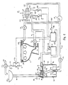
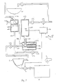
- Figure 1 is a schematic diagram of a vacuum toilet system in accordance with the present invention, including a toilet bowl, a grey water reservoir and a pump, the toilet system being shown in its normal operating condition, immediately before a flush cycle,
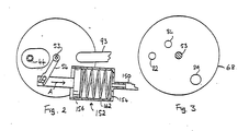
- Figure 2 is a top plan view, partly in section, of the grey water reservoir when the toilet system is in its normal operating condition,
- Figure 3 is a top plan view of the disc member of a disc valve that is incorporated in the grey water reservoir,
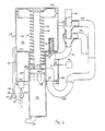
- Figure 4 is a sectional view of a combination pump and grey water reservoir used in a modification of the system shown in Figure 1,
- Figure 5 is a part sectional schematic view of a second vacuum toilet system in accordance with the present invention,
- Figure 6 is a sectional view taken on the line VI-VI of Figure 5, and
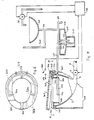
- Figure 7 is a schematic illustration of a third vacuum toilet system in accordance with the present invention.
- In the various Figures, like reference numerals designate corresponding components.
- The vacuum toilet system illustrated in Figure 1 is designed to be installed in a pressurized aircraft and comprises a
toilet bowl 2 which defines an interior space for receiving waste material and has anoutlet opening 4. The outlet opening is connected to one side of an electrically drivendischarge valve 6, and the opposite side of the discharge valve is connected through asewer pipe 8 to aholding tank 10. Thedischarge valve 6 controls flow of material from the toilet bowl to the holding tank. A pressure difference of about 250 mbar is required to operate the system illustrated in Figure 1. Sufficient pressure difference for operating the system exists between the cabin of the aircraft and the ambient atmosphere when the aircraft is at an altitude greater than about 5,000 m. If there is insufficient pressure difference between the cabin of the aircraft and the ambient atmosphere, ablower 12 is used to establish a sufficient pressure difference. Reference may be made to US-A-4713847 for further information regarding the manner in which material is transported to the tank and removed from the tank. - The vacuum toilet system also comprises a
hand basin 40 having acold water valve 42, and anoutlet pipe 44. Thecold water valve 42 is connected through apipe 46 to a source (not shown) of water under pressure. Thecold water valve 42 is solenoid-operated and automatically closing. When a user presses a button (not shown), aswitch 48 is closed to supply electrical current to asolenoid 50, which opens thevalve 42. When the supply of current is discontinued, e.g. by removing pressure from the button holding theswitch 48 closed, thevalve 42 recloses. A secondary coldwater supply switch 52 is connected in parallel with theswitch 48. - The outlet pipe of the
hand basin 40 is connected to agrey water reservoir 62. The grey water reservoir comprises alower housing 64 and an upper housing 66. The upper and lower housings define threepassages valve disc 68, which hasopenings valve disc 68 is located between the upper andlower housing 64, 66 and is mounted on ashaft 53, which is rotatably supported by thehousings 64 and 66. - The
disc 68 is coupled through theshaft 53 and an arm 54 (Figure 2) that extends radially of theshaft 53 to a vacuum-actuatedmotor 152 which is operable to rotate thedisc 68 selectively to a position in which the passage 70 is open or a position in which thepassages motor 152 comprises acylinder 154 in which a piston 156 is slidingly fitted so that it defines a chamber of variable volume. The piston 156 is provided with a piston rod operating thearm 54 as shown in Figure 2. Aspring 162 urges the piston 156 towards the position shown, in which the passage 70 is open. When the piston 156 is in another end position more to the right of that shown in Figure 2, thepassages - The
outlet pipe 44 enters thereservoir 62 through an inlet opening 76 aligned with the passage 70 and in open communication with thepassage 72. However, asleeve 80 extends downwardly from theopening 76 and a wall 87 extends upwardly from an edge of thepassage 72, to a level above the lower end of thesleeve 80, and therefore water that passes through theopening 76 will not enter thepassage 72 unless the passage 70 is closed and thepassage 72 is open. - The
passage 74, which, like the passage 70, is in direct, open communication with the interior space of thereservoir 62, is connected through apipe 93 to thesewer pipe 8 at a point downstream of thedischarge valve 6. - An
overflow pipe 88, which is connected to a drain system under cabin pressure, branches from theoutlet pipe 44 just above thereservoir 62. Thereservoir 62 is provided with a level detector 91, which provides an electrical signal in the event that the free surface of water in the reservoir falls below the level detector 91. - At the bottom of the
reservoir 62 there is a discharge opening 94 which is coupled to thepassage 72 by apipe 98. At its lower end, thepipe 98 is formed withopenings 102 and is surrounded by a filter 106. - The discharge opening 94 at the bottom of the
reservoir 62 is connected through a pipe 110, provided with acheck valve 114, to a pressure actuatedpump 118. The pump is also connected through a rinsewater supply pipe 135, provided with acheck valve 136, to aspray nozzle system 138 at the rim of thetoilet bowl 2. - The
pump 118 is connected to oneport 128 of a three-way solenoid valve 130. Thevalve 130 has asecond port 144, which is connected to thesewer pipe 8, and athird port 148, which is exposed to cabin pressure P₁. Thevalve 130 is controlled by aswitch 149 via asolenoid 147. When theswitch 149 is closed, thesolenoid 147 operates thevalve 130 to connect theport 128 to theport 144 and the partial vacuum applied to the outlet of thepump 118, via thesewer pipe 8, causes a metered quantity of water to be discharged from the pump by way of thepipe 135. When theswitch 149 is open, the valve connects theport 128 to theport 148 so that cabin pressure is applied to the pump and water is drawn into the pump from the pipe 110. A second solenoid valve 170, whosesolenoid 173 is controlled by aswitch 171, has one port 172 exposed to cabin pressure P₁, asecond port 174 connected to thesewer pipe 8, and athird port 176 connected through apipe 150 to the motor 152 (Figure 2). When theswitch 171 is open,solenoid 173 is deenergised and the valve 170 communicates cabin pres sure P₁ to themotor 152, and thespring 162 urges the piston 156 to the position shown in Figure 2 so that thedisc 68 is placed in the position in which the passage 70 is open. When theswitch 171 is closed, the valve 170 moves to connect the pressure insewer pipe 8 to themotor 152 so that the piston 156 moves in the direction of the arrow A in Figure 2 and thepassages - A
flush control unit 180 receives inputs from aflush initiation switch 182, which is controlled by a flush control button (not shown), and the level detector 91, and provides outputs to control the states of thedischarge valve 6 and theswitches flush control unit 180 may also receive other inputs and provide other outputs but these are not germane to the present invention and will not be discussed. - The
flush control unit 180 has two modes of operation, namely a normal flush mode and a backwash mode. In the normal flush mode, theunit 180 ensures that the level of water in thereservoir 62 remains at least as high as the level detector 91. If the water level in thereservoir 62 falls below the level detector 91, theunit 180 closes theswitch 52 and thevalve 42 opens and cold water is supplied to thereservoir 62 for a predetermined time. The volume of water in the reservoir is then greater than that required for one flush cycle. If thereservoir 62 is filled, and water backs up in theoutlet pipe 44 to theoverflow pipe 88, any additional water entering thepipe 44 overflows through thepipe 88 and is discharged from the aircraft by way of the drain mast (not shown). - When the flush control button is pressed, the
switch 182 is closed and theunit 180 responds by initiating a flush cycle. During the flush cycle, theunit 180 opens and closes thedischarge valve 6, to remove waste material from thebowl 2, and causes rinse water to be supplied to thebowl 2. Theunit 180 ensures that a sufficient degree of vacuum exists in the holding tank, but the manner in which this is achieved is not pertinent to the invention and will not be described herein. Reference may be made to US-A-4713867. The present invention is concerned with the means whereby the rinse water is supplied. - At a predetermined time in the flush cycle, the
unit 180 closes theswitch 149 and thereby actuates thevalve 130 to connect theport 144 to thepump 118, so that water is discharged from the pump through the rinsewater supply pipe 135 and thecheck valve 136 to thespray nozzle system 138. Subsequently, theunit 180 opens theswitch 149 and thevalve 130 places theport 148 in communication with the pump, so that water is drawn from thereservoir 62 through the filter 106, the discharge opening 94, the pipe 110 and thecheck valve 114, into thepump 118, recharging thepump 118. - In order to prevent the filter 106 from becoming blocked, it is necessary to clean it from time to time. This is accomplished when the aircraft is being serviced, by operating in the backwash mode. In the backwash mode, the
unit 180 energizes theblower 12 for establishing the required partial vacuum in theholding tank 10. Theunit 180 also closes theswitch 52 so that thecold water valve 42 is opened, supplying clean water to thehand basin 40. When sufficient time has elapsed to ensure that any solid material in the hand basin or theoutlet pipe 44 will have been washed into thereservoir 62, theswitch 52 is opened. Theswitch 171 is then closed so that the solenoid valve 170 connects theport 174 to theport 176, applying vacuum to themotor 152. Consequently, thedisc 68 is turned, closing the passage 70, so that air cannot enter thereservoir 62 through that passage, and opening thepassages passage 74 applies a subatmospheric pressure to the interior of thereservoir 62, and therefore a flow of air is established from the hand basin through theoutlet pipe 44, thepassage 72, thepipe 98, theapertures 102, the filter 106, the interior space of thereservoir 62 and thepassage 74, into thepipe 93. This flow of air displaces solid material from the filter and ensures that the solid material does not settle into the bottom of thereservoir 62 but is entrained in the flow and is removed from the reservoir by way of thepassage 74, thepipe 93 and thesewer pipe 8. - The vacuum toilet system shown in Figures 1 to 3 allows use of grey water for rinsing the water-receiving
bowl 2, and thus reduces the amount of water that needs to be carried by an aircraft equipped with a non-circulating vacuum toilet system. The system is not limited to the use of grey water for toilet rinsing, and does not require that all grey water be used for toilet rinsing or otherwise delivered to the holding tank. - Figure 4 shows a modification of the system of Figures 1 to 3, in which the
reservoir 62 is integrated with thepump 118. Thepump 118 comprises a housing that defines two coaxial cylindrical bores, and acompound piston member 134 that has large andsmall diameter pistons rod 210. Thepistons chambers piston member 134, are formed. A spring 140 urges thepiston member 134 towards the position in which thechambers reservoir 62 is annular and surrounds the smaller bore of thepump 118 over part of its length and has anannular bottom wall 202. Thesmaller piston 208 incorporates thecheck valve 114, depicted schematically as a flap covering a hole in the smaller piston. Thechamber 126 is separated from thereservoir 62 by a wall 212 and therod 210 extends through an opening in the wall 212. Theopenings 102 are formed in the wall of thechamber 122. - The
outlet pipe 44 opens at its lower end into thereservoir 62 through aport 216, which is controlled by avalve 221, normally held open by a spring-loadedplunger 224 which extends through the wall 212. The filter 106 is seated against thebottom wall 202 of thereservoir 62 and extends above theholes 102. - The
bottom wall 202 is formed with aport 252 which communicates through a normally-closedvalve 254 with thevacuum sewer pipe 8. Thewall 202 is also formed with aport 260, which is connected to the lower end of apipe 262, the upper end of which is connected to theoutlet pipe 44 above the level of theoverflow pipe 88. - When the
valve 130 is in its normal position, so that it communicates cabin pressure to thechamber 126, the spring 140 forces thecompound piston member 134 upwards, to the position shown in Figure 4. Assuming that thechamber 122 and thereservoir 62 are empty, grey water from the hand basin flows through thepipe 44 and into thereservoir 62 through theport 216. Thevalve 254 is closed, and therefore the grey water drains through the filter 106 into thechamber 122 and fills the rinsewater pipe 135. Assuming that sufficient grey water is supplied, thereservoir 62 and itsfeed pipe 44 are filed to the level of theoverflow pipe 88. Theoverflow pipe 88 is slightly below thespray nozzle system 138, and therefore excess grey water will overflow through thepipe 88 and not through the spray nozzle system. Water also drains into thepipe 262, which is filled to the level of the overflow pipe. When the flush control button is pressed, the flush control unit 180 (Figure 1) causes thevalve 130 to swing to its second position, thereby closing to cabin pressure and opening to vacuum. Partial vacuum is applied to thechamber 126, and cabin pressure applied to the top of thelarger piston 206 forces thepiston assembly 134 downwards against the force of the spring 140. The water in thechamber 122 is pressurized and is expelled from thechamber 122 through the rinsewater pipe 135 and thespray nozzle system 138. As thepiston assembly 134 moves down, water in thereservoir 62 drains through the filter 106, filling the space on top of thesmaller piston 208. After sufficient time for the piston assembly to reach its bottom position, e.g. about 0.5 seconds, thevalve 130 swings back to its normal position, disconnecting thechamber 126 from the pressure in the sewer pipe and connecting it to cabin pressure. The spring 140 pushes thepiston assembly 134 back to its top position, while thecheck valve 114 in thesmaller piston 208 allows water to pass from the upper side of thepiston 208 to the lower side thereof, filling thechamber 122. Thus, the pump is ready for the next stroke. - In the event that the level of water in the
reservoir 62 falls below the level detector 91, the level detector provides a signal to theflush control unit 180, and theunit 180 closes theswitch 52 so that potable water is supplied to thebasin 40 to restore the level of water in thereservoir 62. - Solid material in the grey water that enters the
reservoir 62 is trapped by the filter 106, so that it does not enter thechamber 122. The filter 106 is cleaned by backwashing as previously described when the aircraft is on the ground. - In order to backwash the filter 106, partial vacuum is established in the
sewer pipe 8 and theunit 180 opens thevalve 254. Any water in thereservoir 62 and theoutlet pipe 44 is removed by way of theport 252. Thevalve 130 is swung to its second position, and thepiston member 134 is forced downwards. When the piston member reaches its bottom position, thelarger piston 206 engages theplunger 224 and forces it downwards, causing thevalve 221 to close theport 216, thereby preventing air from entering thereservoir 62 by way of theport 216. Therefore, water present in thepipe 262 is drawn into the reservoir and passes through the filter 106 in the reverse direction, removing solid material deposited on the exterior of the filter. When the water has been exhausted from thepipe 262, air is drawn into the reservoir through thepipe 262 and the filter 106. Solid material removed from the filter is removed from thereservoir 62 by way of theport 252 and enters thesewer pipe 8. After sufficient time to ensure a reliable backwash, for example about 5 seconds, thevalve 254 is closed and thevalve 130 is swung to its normal position. - It will be appreciated that during normal flush, the
valve 221 will be closed if partial vacuum is applied to thechamber 126 for a sufficient time, but this has no effect on operation of the vacuum toilet system. - The systems described with reference to Figures 1 to 4 are subject to disadvantages, in that each includes a pump and valves and requires a filter to protect the pump and valves, and to prevent blockage of the spray nozzle system. Moreover, each includes a level detector to ensure that there will always be sufficient water in the
reservoir 62 to execute a flush. Since a large passenger aircraft might have about 15 toilets, each with its own reservoir and level detector, the risk of failure of a level detector is significant, and if a level detector fails, the entire potable water system might be emptied. Further, in the systems shown in Figures 1 to 4, the flow of air into thebowl 2 does not have a significant cleansing effect. - In the system illustrated in Figures 5 and 6, the waste-receiving
bowl 2 is mounted in anexternal shroud 300 which is spaced from the bowl. An air supply member 302 made of moulded synthetic polymer material is secured to the rim of thebowl 2 and bridges the space between thebowl 2 and theshroud 300. The member 302 is generally annular and includes aflange 304 which extends downwardly into the bowl in spaced relationship from the interior surface thereof. Accordingly, anannular channel 306 is defined between theflange 304 and the interior surface of thebowl 2. - Inside the
bowl 2 is a rinsewater distribution pipe 320 which extends about two-thirds of the way around the bowl. The pipe opens into theannular channel 306 by way of threeports 324, one at each end of thepipe 320 and one intermediate its ends. A deflector plate (not shown) is positioned in front of eachport 324. In a modification of the system shown in Figures 5 and 6, the rinsewater distribution pipe 320 might extend about three-quarters of the way around thebowl 2 and have four outlet ports spaced approximately equally around thebowl 2. - The rinse
water distribution pipe 320 is connected by a rinsewater supply pipe 328 to areservoir 338, which receives grey water from thehand basin 40. Thereservoir 338 is preferably placed close to thebowl 2, in order to minimize the length of thepipe 328. However, it might alternatively be placed directly below thehand basin 40 like an enlarged water trap. Thereservoir 338 is divided into upper andlower compartments wall 344 formed with ahole 346 for liquid flow. The rinsewater supply pipe 328 extends almost to the bottom of thelower compartment 342, and is formed with asmall vent hole 350 just below the top of theupper compartment 340. Thedrain pipe 44 is configured so that it drains easily into thereservoir 338. Theoverflow 88 is placed close to thereservoir 338 to minimize the amount of water stored in thepipe 44 when the reservoir is filled up to the level of the overflow. Thedrain pipe 44 opens into thelower compartment 342, and when the lower compartment is full, additional grey water delivered into the lower compartment enters the upper compartment through thehole 346. When full, thelower compartment 342 contains enough water for one flush of thebowl 2, for example about 200 ml. The aircraft cabin pressure is communicated to thelower compartment 342 by thedrain pipe 44 and by the rinsewater supply pipe 328, thevent hole 350 and thehole 346. - The air supply member 302 is formed with
numerous bores 352 which extend into thechannel 306. Thebores 352 are spaced apart around the member 302. In a practical implementation of the invention, there may be eightysuch bores 352. For clarity of illustration, thebores 352 are shown in Figure 5 as extending radially, but in fact the bores are inclined at an angle of about 5 to 10° from the radial direction and all extend into thechannel 306 in the counterclockwise direction with respect to the member 302, when viewed in plan. At its upper surface, the air supply member 302 is formed withgrooves 358. Thegrooves 358 extend semi-tangentially with respect to the member 302 and are all directed inwardly in the counterclockwise direction when viewed from above. Of course, thebores 352 andgrooves 358 may be directed clockwise instead of counter-clockwise into thetoilet bowl 2. - The
bowl 2 is provided with aseat 360 and acover 362. The seat and the cover are mounted to the air supply member 302 by a hinge 364. When theseat 360 is lowered, it engages the air supply member 302 and closes thegrooves 358 at the top. Theseat 360 is formed with agap 366 at the front of the toilet bowl. Thecover 362 is shaped so that when it is lowered, the aircraft cabin is not in direct open communication with the interior of the toilet bowl through thegap 366. The purpose of thegap 366 is to provide a rapid flow of air into the toilet bowl, and thereby prevent build-up of underpressure therein, in the event of a malfunction that causes thevalve 6 to open when the toilet is in use. - The
cover 362 operates theflush initiation switch 182, which is shown only schematically in Figure 5. Theswitch 182 is closed automatically when the cover is closed, and remains open when the cover is open. - When the
cover 362 is lowered, theflush control unit 180 issues a flush signal in response to the closing of theswitch 182, and thedischarge valve 6 is opened. Suction is applied to the interior space of thebowl 2, and this suction ensures that the cover is held down in firm, sealing relationship against the seat. Due to the partial vacuum established in the interior space of thebowl 2, air is drawn into the interior space of the bowl through thegrooves 358 and thebores 352. The air that enters theannular channel 306 through thebores 352 has a substantial peripheral component of velocity and therefore executes a swirling motion about the interior space of the bowl. The air entering the toilet bowl through thegrooves 358 executes a similar swirling motion. - When partial vacuum is established in the toilet bowl, suction is applied through the
ports 324 and thewater distribution pipe 320 to thewater supply pipe 328. Water is drawn into thepipe 328 from thelower compartment 342 and is discharged into thechannel 306 through theports 324. The water leaving thepipe 320 through theports 324 impinges on the deflector plates (not shown), which cause the water to spray upwards and to the side. The water entering thechannel 306 is entrained into the swirling flow of air from thebores 352 and executes a similar swirling motion, cleansing the interior surface of the bowl. The flow of air adds kinetic energy to the flow of rinse water, enhancing the cleaning action of the water. The turbulent motion of air and water in the bowl may create a mist, which may flow upwards in the space defined by the interior surface of theflange 304 and result in deposit of mist droplets on the underside of thecover 362 and on theseat 360. This upward flow of mist is inhibited by the flow of air through thegrooves 358. - When suction is applied to the
water supply pipe 328, some air or water (depending on the filling level of the reservoir 338) is drawn from theupper compartment 340 into thepipe 328. When the liquid level in the lower compartment has fallen below the lower end of thepipe 44, air is sucked into thereservoir 338 through thevent 348. Since the air enters the lower compartment and is passing upwards through thehole 346, the lower compartment is in throttled communication with the upper compartment and the lower compartment is not refilled by gravity flow from the upper compartment during a flush but only when the flush operation is completed. - When the
discharge valve 6 is closed, water from theupper compartment 340 drains into thelower compartment 342, refilling the lower compartment. Thus, thereservoir 338 functions as a metering device which, at each flush, delivers a volume of water approximately equal to the volume of the lower compartment plus the volume of water in thepipes pipes - The
pipe 328 slopes downwards towards the reservoir, so that when a flush is completed, water remaining in the pipe drains back into the reservoir, minimizing grey water usage. - In an aircraft, the degree of partial vacuum that is established in the toilet bowl when the discharge valve is opened can vary quite widely. Also, in some aircraft vacuum toilet systems the flush time depends on the location of the toilet bowl (forward or aft). Therefore, the
reservoir 338 is designed so that at low vacuum and short flush time, the lower compartment of the reservoir is just barely emptied. At higher vacuum and/or longer flush time, the lower compartment is emptied well before thedischarge valve 6 is closed. - For proper functioning of the system shown in Figures 5 and 6, it is necessary that the flow resistances of the three paths for delivering air and water to the toilet bowl be balanced, so that the functions of the various flows are achieved. The proper balance is best achieved through experimentation. For example, it has been found that the greater part of the air flow should be provided through the
bores 352. - When the aircraft is first brought into service at the beginning of a working day, the
flush control unit 180 automatically performs a power-up routine in which it opens thehand basin valve 42 for sufficient time to provide enough water to give up to five flushes. Theunit 180 counts the number of flushes during the day and the number of times that the hand basin valve is opened under manual control, and utilizes this information to determine when there is a danger that thereservoir 338 is approaching an empty condition. If the flush control unit determines that the reservoir is approaching an empty condition, it causes the hand basin valve to open and provide additional water to the reservoir. In this manner, the need for a level detector in the reservoir is avoided. Moreover, because the water supplied through theoutlet ports 324 is effectively distributed over the interior surface of the toilet bowl by the flow of air entering the toilet bowl, there is no need for fine spray nozzles. Furthermore, there are no valves or pumps between thereservoir 338 and theports 324. Accordingly, the need for a filter is avoided and this in turn avoids the need to be able to backwash the filter. Of course, a strainer may be provided in the outlet of the hand basin or in thedrain pipe 44 connected thereto to catch objects such as matches and buttons. - The swirling flow of air that enters the toilet bowl in the system of Figures 5 and 6 is quite effective at cleansing the toilet bowl even without the aid of rinse water. Therefore, in a modification of the system of Figures 5 and 6, the
flush control unit 180 is designed without the ability to count the number of flushes, so that if the reservoir runs dry, the toilet bowl is cleansed by the air flow only. In fact, the likelihood of the reservoir running dry is quite small, because normally more grey water is produced through use of the hand basin than is required for toilet flushings. - The toilet system shown in Figures 5 and 6 is not restricted to use on an aircraft, and a system similar to that shown might be installed in a ship or train, for example. In the case of a system designed for use otherwise than on an aircraft, factors relating to the type of installation might dictate modifications. For example, in the case of a system on a ship, where the volume of waste is unimportant because it is pumped overboard, the
pipe 328 might slope down towards the toilet bowl so that at the end of a flush, water in thepipe 328 drains into the toilet bowl and forms a pool of water. In a toilet system on a train, the degree of vacuum and the flush time is not subject to large variation, and therefore a simpler reservoir may be employed. In such a reservoir, there would be distinct upper and lower compartments, and the volume of grey water withdrawn on each flush would be determined just by the degree of partial vacuum and the flush time. - When designed for use in an aircraft, a vacuum toilet system as shown in Figures 1 to 3, possibly modified in accordance with Figure 4, or as shown in Figures 5 and 6, may be incorporated in a self-supporting module that is installed in the aircraft as a unit. The module comprises a toilet bowl and associated discharge valve, a hand basin, a reservoir and, in the case of the system of Figures 1 to 4, a pump and filter. The module is self-contained except for connections to the vacuum sewer pipe, the potable water supply and, if necessary, the aircraft drain system. In the aforesaid modification of the Figures 5 and 6 system, where no overflow pipe is provided, relocation of the toilet module is facilitated because there is then no gravity line leaving the module.
- Figure 7 illustrates a grey water flush system developed for use on a railway train. It will be appreciated that space and weight constraints are not generally as severe on a train as on an aircraft, and moreover variations in the direction of gravity relative to railway carriages are not as great as the variations in the direction of gravity relative to an aircraft.
- In the toilet system shown in Figure 7, the
drain pipe 44 opens into agrey water reservoir 400 having an upper compartment 404 and alower compartment 406 separated by a wall 410 formed with ahole 412. A float 416 is disposed in the upper compartment 404, which compartment is connected to an overflow 420. - A
tube 424 connects the bottom of thereservoir 400 to afilter housing 432. The interior space of the filter housing is divided into inner andouter chambers filter element 438. Thetube 424 opens into theouter chamber 436. The inner chamber of the filter housing is in direct open communication, through atube 442, with the inlet side of apump 446, the outlet side of which is connected to the spray nozzles of thetoilet bowl 2. - A
clean water reservoir 450 is mounted adjacent to thegrey water reservoir 400. Theclean water reservoir 450 is connected to the train's potable water supply through acheck valve 454 and asolenoid valve 456. Theclean water reservoir 450 has an air vent opening 452 at its top and is connected at its bottom by atube 460 to theinner chamber 434 of thefilter housing 432. Theclean water reservoir 450 is provided with alevel sensor 464. If the level of water in the clean water reservoir falls below the level sensor, the level sensor issues a signal to theflush control unit 180, and theunit 180 in turn issues a signal that causes thesolenoid valve 456 to open, supplying water to refill the clean water reservoir to a level above the level sensor. Theouter chamber 436 of the filter housing 423 is connected to the top of theupper compartment 406 of the grey water reservoir by atube 468. Thegrey water reservoir 400 and theclean water reservoir 450 communicate through the filter. Therefore, the level of grey water in thetube 468 and thetube 424 of thereservoir 400 is the same as the level of water in thereservoir 450. - Each time the
control unit 180 receives a flush signal from theswitch 182, it energizes thepump 446 for sufficient time to draw a predetermined volume of water from the filter housing and deliver it to the spray nozzles in thebowl 2. This volume of water is about the same as that used for aircraft vacuum toilets, i.e. about 200 to 250 ml. Thepump 446 draws water from theinner chamber 434 of thefilter housing 432. Because the filter has a finite flow resistance and thetube 460 is of considerably larger diameter than thetube 424, most of the water drawn by the pump is taken from theclean water reservoir 450, and relatively little is drawn through the filter 428 from theouter chamber 436 . However, when the flush control unit switches the pump off, grey water from thereservoir 400 is able to flow through the filter and replenish the clean water reservoir. The grey water is thus ready for immediate delivery to the toilet bowl by thepump 446. - The
reservoir 400 acts as a buffer that allows thefilter 438 to pass grey water at a slower rate than that at which it is supplied by thehand basin 40, thus minimizing the volume of grey water that needs to be discharged through the overflow 420. - The
tube 424 is connected through avalve 472 to a tube 476. In order to clean the system and backwash the filter, the tube 476 is connected to a source of partial vacuum and thevalve 472 is opened. Provided the level of water in thereservoir 400 is below the level of the wall 410, the float 416 seals thehole 412 and prevents water from being drawn from thereservoir 400. Consequently, the suction applied to theouter filter chamber 436 results in clean water from thereservoir 450 being drawn through the filter into theouter chamber 436, dislodging solid material from the filter. The solid material is entrained in the flow of water and is removed from the system through the pipe 476. When thereservoir 450 and thetube 460 are empty of water, air is drawn through thefilter 438 and enters the outer chamber of the filter housing. This air displaces water from thetube 468 and enters thecompartment 406 and allows the water and any solid material in thecompartment 406 to be removed by way of thetube 424. - It will be appreciated that the present invention is not restricted to the particular embodiments that have been described and illustrated, and that variations may be made therein without departing from the scope of the invention as defined in the following claims.
- For example, in a modification of the system of Figures 1 to 3, the
switch 48 is not connected directly to thesolenoid 50. On closing theswitch 48, a signal is sent to theflush control unit 180, which closes theswitch 52, and thereby energizes thesolenoid 50, for a predetermined time. The toilet system described with reference to Figures 1 to 3 is not restricted to use in aircraft, and may be applied to other transport vehicles such as trains and buses, and is not restricted to the particular types of pump and motor that have been illustrated. The system described with reference to Figures 5 and 6 is not restricted to the particular number and arrangement of bores and grooves, and it is not essential to the invention that the grooves be directed to induce a swirling motion in the same sense as that induced by the bores. Indeed, the grooves may be directed radially, so as not to induce any swirling motion. In order to augment the swirling motion of the air that enters through thebores 352, guiding ribs may be provided at the radially outer surface of theflange 304, the ribs being inclined downwards in the counterclockwise direction. Further, although each of the illustrated systems includes an overflow for excess grey water, such an overflow is not always essential. Thus, in the case of the system shown in Figures 5 and 6, if theoverflow 88 were omitted the excess grey water would flow into thebowl 2 and thence into the waste tank, and so long as the waste tank were large enough to accommodate the extra grey water, this would not present a problem.
Claims (16)
Priority Applications (2)
| Application Number | Priority Date | Filing Date | Title |
|---|---|---|---|
| AT89308950T ATE100396T1 (en) | 1988-09-06 | 1989-09-05 | VACUUM TOILET SYSTEM. |
| EP92118730A EP0530859B1 (en) | 1988-09-06 | 1989-09-05 | Vacuum toilet system |
Applications Claiming Priority (4)
| Application Number | Priority Date | Filing Date | Title |
|---|---|---|---|
| SE8803119A SE502453C2 (en) | 1988-09-06 | 1988-09-06 | Aircraft vacuum toilet and washing basin system |
| SE8803120 | 1988-09-06 | ||
| SE8803120A SE8803120D0 (en) | 1988-09-06 | 1988-09-06 | SET TO RINSE A TOILET CHAIR IN A VACUUM DRAINAGE SYSTEM WITH A DEVICE FOR IMPLEMENTATION OF THE SET |
| SE8803119 | 1988-09-06 |
Related Child Applications (1)
| Application Number | Title | Priority Date | Filing Date |
|---|---|---|---|
| EP92118730.8 Division-Into | 1989-09-05 |
Publications (2)
| Publication Number | Publication Date |
|---|---|
| EP0363012A1 true EP0363012A1 (en) | 1990-04-11 |
| EP0363012B1 EP0363012B1 (en) | 1994-01-19 |
Family
ID=26660294
Family Applications (2)
| Application Number | Title | Priority Date | Filing Date |
|---|---|---|---|
| EP92118730A Expired - Lifetime EP0530859B1 (en) | 1988-09-06 | 1989-09-05 | Vacuum toilet system |
| EP89308950A Expired - Lifetime EP0363012B1 (en) | 1988-09-06 | 1989-09-05 | Vacuum toilet system |
Family Applications Before (1)
| Application Number | Title | Priority Date | Filing Date |
|---|---|---|---|
| EP92118730A Expired - Lifetime EP0530859B1 (en) | 1988-09-06 | 1989-09-05 | Vacuum toilet system |
Country Status (7)
| Country | Link |
|---|---|
| US (2) | US5245711A (en) |
| EP (2) | EP0530859B1 (en) |
| JP (1) | JP2836856B2 (en) |
| AT (1) | ATE146735T1 (en) |
| CA (1) | CA1335859C (en) |
| DE (2) | DE68927589T2 (en) |
| ES (2) | ES2096697T3 (en) |
Cited By (24)
| Publication number | Priority date | Publication date | Assignee | Title |
|---|---|---|---|---|
| GB2248858A (en) * | 1990-10-17 | 1992-04-22 | Metra Oy Ab | Vacuum toilet system with treated rinse liquid |
| FR2668187A1 (en) * | 1991-10-16 | 1992-04-24 | Metra Oy Ab | WC system operating by suction and using a treated rinsing liquid, and method for operating such a system |
| EP0492988A2 (en) * | 1990-12-21 | 1992-07-01 | Japanic Corporation | Toilet and sewage disposal apparatus therefor |
| EP0515134A1 (en) * | 1991-05-23 | 1992-11-25 | Evac Ab | Improvements in and relating to vacuum sewage systems |
| DE4227517A1 (en) * | 1991-09-30 | 1993-04-08 | Airbus Gmbh | DEVICE FOR WATER DISPOSAL |
| FR2715953A1 (en) * | 1994-02-08 | 1995-08-11 | Ragot Claude | Mains-connected WC bowl, with tipping inner basin |
| WO2000012383A1 (en) | 1998-08-29 | 2000-03-09 | Aoa Apparatebau Gauting Gmbh | Vacuum toilet system for a vehicle |
| EP1063167A2 (en) | 1999-06-24 | 2000-12-27 | EADS Airbus GmbH | Toilet system, particularly for vehicles |
| US6401270B1 (en) * | 1998-04-15 | 2002-06-11 | Garry Moore | Toilet apparatus |
| DE10102298C1 (en) * | 2001-01-19 | 2002-08-22 | Airbus Gmbh | Toilet facilities, in particular for transportation |
| DE10100962C2 (en) * | 2001-01-11 | 2003-09-25 | Airbus Gmbh | Toilet facilities, in particular for transportation |
| US6977005B2 (en) | 1999-06-24 | 2005-12-20 | Airbus Deutschland Gmbh | Waterless vacuum toilet system for aircraft |
| WO2007002329A1 (en) * | 2005-06-23 | 2007-01-04 | Mag Aerospace Industries, Inc. | Vacuum toilet assembly |
| US7533426B2 (en) | 2005-06-24 | 2009-05-19 | Mag Aerospace Industries, Inc. | Gray water interface valve systems and methods |
| CN101806085B (en) * | 2009-02-13 | 2011-11-16 | 张祖安 | Recycling water closet |
| WO2013172953A1 (en) * | 2012-05-17 | 2013-11-21 | Mag Aerospace Industries, Inc. | Two-stage flush and grey water flush systems and devices |
| EP2690015A1 (en) * | 2012-07-23 | 2014-01-29 | Airbus Operations GmbH | Combination of vacuum toilet and grey water system functions |
| US20140138326A1 (en) * | 2012-11-16 | 2014-05-22 | Mag Aerospace Industries, Inc. | Mixed fluid filtration system |
| EP2873583A1 (en) * | 2013-11-19 | 2015-05-20 | ALSTOM Transport Technologies | System for storing and dispensing water for a compact toilet |
| US9182042B2 (en) | 2013-03-15 | 2015-11-10 | Mag Aerospace Industries, Llc | Mixed media orbital valve |
| US9371135B2 (en) | 2012-05-17 | 2016-06-21 | Mag Aerospace Industries, Llc | Toilet concepts |
| EP3063338A4 (en) * | 2013-10-29 | 2017-07-12 | Huynh, Quang Le | Water saving toilet system |
| US10400434B2 (en) | 2015-12-01 | 2019-09-03 | Semilla Corporation | Vacuum toilet system |
| CN111188397A (en) * | 2020-01-19 | 2020-05-22 | 何秀玲 | Vacuum closestool secondary cleaning device for high-speed railway |
Families Citing this family (58)
| Publication number | Priority date | Publication date | Assignee | Title |
|---|---|---|---|---|
| FI99156C (en) * | 1993-04-19 | 1997-10-10 | Evac Ab | Electric controller |
| US5408704A (en) * | 1993-09-09 | 1995-04-25 | Sealand Technology, Inc. | Low volume vacuum toilet assembly |
| KR0168326B1 (en) * | 1994-09-01 | 1999-01-15 | 스미요 가나이 | Bed system with excretion collecting means |
| US5739612A (en) * | 1996-09-03 | 1998-04-14 | Davenport; Norban Earl | Auxiliary power source |
| US5980756A (en) * | 1996-09-20 | 1999-11-09 | Tracy; Thomas R. | Treatment method and system for aircraft toilet waste water |
| US5853579A (en) * | 1996-11-26 | 1998-12-29 | Wastech International Inc. | Treatment system |
| US6012678A (en) * | 1998-01-26 | 2000-01-11 | The Boeing Company | Galley vacuum waste disposal system |
| US6223361B1 (en) | 1998-05-13 | 2001-05-01 | Mag Aerospace Industries, Inc. | Galley waste disposal system |
| DE19834537A1 (en) | 1998-07-31 | 2000-02-10 | Gauting Gmbh Apparatebau | Vacuum toilet system for a vehicle |
| PL352611A1 (en) | 1999-07-12 | 2003-08-25 | Clewer Ltd Oy | Method of purifying water, suitable bacteria for the method and use thereof |
| US6256802B1 (en) | 2000-03-21 | 2001-07-10 | Evac International Oy | Apparatus for injecting a reagent into a stream of rinse fluid |
| FI111289B (en) * | 2000-07-10 | 2003-06-30 | Evac Int Oy | vacuum System |
| US6434759B1 (en) * | 2001-07-02 | 2002-08-20 | Evac International Oy | Automatically operable lid for a vacuum waste receptacle |
| US7207073B1 (en) | 2001-10-18 | 2007-04-24 | The American Team | Vacuum assisted toilet |
| DE10229799A1 (en) * | 2002-07-03 | 2004-01-29 | Airbus Deutschland Gmbh | Process for the treatment and reuse of gray water for flushing toilets in vacuum systems |
| US6702942B1 (en) * | 2002-12-11 | 2004-03-09 | Richard E. Nield | Water conservation device, kit and method of using |
| DE10259997B4 (en) * | 2002-12-20 | 2007-09-13 | Airbus Deutschland Gmbh | Aircraft toilet system |
| DE10349158A1 (en) * | 2003-10-22 | 2005-06-16 | Airbus Deutschland Gmbh | Device for water supply in aircraft |
| US7987527B1 (en) | 2004-12-14 | 2011-08-02 | Shumaker James J | Toilet ventilation device |
| DE102005006136B4 (en) | 2005-02-10 | 2010-02-04 | Airbus Deutschland Gmbh | Airplane with gray water utilization system |
| WO2007015403A1 (en) * | 2005-08-01 | 2007-02-08 | Inax Corporation | Toilet bowl flushing device and toilet bowl flushing method |
| DE102005054887B4 (en) * | 2005-11-17 | 2013-07-18 | Airbus Operations Gmbh | System for flushing a vacuum WC |
| CN101583766A (en) * | 2006-10-24 | 2009-11-18 | 欧沃德·阿巴迪 | Toilet flushing system and method without using a toilet tank |
| DE102009013554B4 (en) * | 2009-03-17 | 2016-03-03 | Airbus Operations Gmbh | Aircraft with a recirculation shower and associated water treatment process |
| DE102009013558B4 (en) * | 2009-03-17 | 2016-02-18 | Airbus Operations Gmbh | Combined Bidet Toilet Construction for Aircraft |
| AU2010239235A1 (en) * | 2009-04-23 | 2011-12-08 | Eckman Environmental Corporation | Grey water recycling apparatus and methods |
| DE102009052046A1 (en) * | 2009-11-05 | 2011-05-12 | Airbus Operations Gmbh | Monitoring device for a vacuum toilet |
| ES2377092B1 (en) * | 2010-06-29 | 2013-01-30 | Santiago Villanueva Lechado | DOSING DEVICE FOR A PRESSURE LIQUID IN A WATER NETWORK. |
| RU2464384C2 (en) * | 2010-08-05 | 2012-10-20 | Владимир Васильевич Масленников | Toilet module |
| RU2447237C1 (en) * | 2010-10-21 | 2012-04-10 | Владимир Васильевич Масленников | Toilet module |
| DE102011088172B4 (en) * | 2011-12-09 | 2014-07-31 | Siemens Aktiengesellschaft | Fresh water supply system for a rail vehicle |
| FR2994965B1 (en) * | 2012-08-31 | 2015-03-27 | Veolia Water Solutions & Tech | DEVICE FOR RECYCLING GRAY WATER IN A TRANSPORT VEHICLE |
| CN102936916B (en) * | 2012-12-11 | 2014-04-16 | 重庆市科学技术研究院 | Household reclaimed water toilet flushing system |
| EP2842870B1 (en) * | 2013-08-30 | 2018-04-18 | Airbus Operations GmbH | Hand treatment device |
| US9668623B2 (en) | 2013-12-14 | 2017-06-06 | Convergent Market Research, Inc. | Waterless toilet system and method with ventilation control |
| JP6329861B2 (en) * | 2014-09-05 | 2018-05-23 | アロン化成株式会社 | Toilet bowl |
| DE102014015991B4 (en) * | 2014-10-28 | 2017-06-08 | Apparatebau Gauting Gmbh | Disposal device for an aircraft and aircraft with the disposal device |
| CN104477191B (en) * | 2014-12-09 | 2017-04-05 | 无锡金鑫集团股份有限公司 | CRH380BK EMUs toilet ash water collection system |
| DE102015000080A1 (en) * | 2015-01-12 | 2016-07-14 | Apparatebau Gauting Gmbh | Pollution detection for pipelines |
| CN104880634A (en) * | 2015-06-07 | 2015-09-02 | 合肥明华机电工程有限公司 | Vehicle-mounted toilet function detection platform |
| CN105270425B (en) * | 2015-11-20 | 2018-07-06 | 山东中车华腾环保科技有限公司 | Intermediate mechanical case vacuumizes and pressue device and its application method |
| US9926693B2 (en) * | 2016-06-20 | 2018-03-27 | Larry McCall | Water-saving accessory for a toilet, basin thereof, and toilet with water-saving feature |
| DE102016218001A1 (en) | 2016-09-20 | 2018-03-22 | Siemens Aktiengesellschaft | Gray water treatment device for a rail vehicle |
| DE102016218002A1 (en) | 2016-09-20 | 2018-03-22 | Siemens Aktiengesellschaft | Gray water treatment device for rail vehicles |
| DE102016217991B4 (en) | 2016-09-20 | 2018-05-03 | Siemens Aktiengesellschaft | Gray water treatment device for a rail vehicle |
| DE102016217986A1 (en) | 2016-09-20 | 2018-03-22 | Siemens Aktiengesellschaft | Water supply device for a rail vehicle |
| US10197072B2 (en) * | 2016-10-19 | 2019-02-05 | Driessen Aerospace Group N.V. | Waste water air stop valve |
| CN106522325A (en) * | 2016-12-30 | 2017-03-22 | 四川建筑职业技术学院 | Squat toilet device convenient to use |
| CN106522324A (en) * | 2016-12-30 | 2017-03-22 | 四川建筑职业技术学院 | Closestool convenient to use |
| US11351935B2 (en) * | 2017-05-04 | 2022-06-07 | Thetford Bv | Wastewater management system for vehicles and related methods |
| CN107268749B (en) * | 2017-07-31 | 2023-11-24 | 江苏中车华腾环保科技有限公司 | Mechanical pressure flushing and draining valve device |
| CN108951782A (en) * | 2018-02-08 | 2018-12-07 | 厦门致杰智能科技有限公司 | A kind of closestool |
| DE102018005366A1 (en) * | 2018-07-05 | 2019-10-10 | Diehl Aviation Gilching Gmbh | Greywater utilization system for an aircraft and method for using greywater in an aircraft |
| RU191383U1 (en) * | 2018-12-10 | 2019-08-05 | Тимченко Михаил Иванович | VACUUM TOILET SYSTEM |
| CN110886360B (en) * | 2019-12-02 | 2021-01-08 | 厚力德机器(杭州)有限公司 | Electroless mechanical air pressure self-opening semi-vacuum toilet |
| US11820513B2 (en) | 2020-04-17 | 2023-11-21 | Goodrich Corporation | Hybrid water storage system for aircraft |
| US11549250B1 (en) * | 2021-08-09 | 2023-01-10 | Calvin Coolridge Barrett | Freshwater conservation drain system |
| CN114606983B (en) * | 2022-03-08 | 2022-12-27 | 山东大学 | Auxiliary device for blocking diffusion of underground water pollutants |
Citations (3)
| Publication number | Priority date | Publication date | Assignee | Title |
|---|---|---|---|---|
| FR2286922A1 (en) * | 1974-10-03 | 1976-04-30 | Monogram Ind Inc | Wash and toilet facility for vehicle - has water from wash basins stored to flush toilet after pre-treatment of waste |
| DE3110558A1 (en) * | 1981-03-18 | 1983-04-07 | Wilhelm Roediger GmbH + Co Haustechnik, 6450 Hanau | WC system |
| DE3536691A1 (en) * | 1985-10-15 | 1987-04-16 | Albert Blum | Water-saving device for toilet flushing |
Family Cites Families (13)
| Publication number | Priority date | Publication date | Assignee | Title |
|---|---|---|---|---|
| US3154796A (en) * | 1963-09-27 | 1964-11-03 | Bruce Ewen Anthony | Water closets |
| US3329974A (en) * | 1964-08-06 | 1967-07-11 | Gen Electric | Flush toilet for zero gravity environments |
| FI44890C (en) * | 1969-08-20 | 1972-01-10 | Waertsilae Oy Ab | Sound attenuation device for water closet. |
| US3786924A (en) * | 1971-07-22 | 1974-01-22 | Delro Inc | Water purification system |
| US3927425A (en) * | 1972-11-08 | 1975-12-23 | Koehler Dayton | Sewerage treatment system |
| US3995328A (en) * | 1974-12-13 | 1976-12-07 | The Boeing Company | Vacuum toilet system |
| US3995327A (en) * | 1975-02-11 | 1976-12-07 | John Richard Hendrick | Water saving toilet arrangement |
| CA1077406A (en) * | 1976-07-16 | 1980-05-13 | Paul A. S. Charles | Filtering elements |
| JPS54160041A (en) * | 1978-06-06 | 1979-12-18 | Matsushita Electric Ind Co Ltd | Drainage reutilizing device |
| US4376314A (en) * | 1981-06-12 | 1983-03-15 | Kidde, Inc. | Vehicular toilet |
| US4521925A (en) * | 1982-06-30 | 1985-06-11 | The Boeing Company | Nonrecirculating vacuum flush toilet system utilizing fresh water |
| DE3500130C2 (en) * | 1985-01-04 | 1995-11-09 | Wuelfing Bautraeger Gmbh | Water supply system for flushing toilets in residential and / or commercial buildings |
| US4713847B1 (en) * | 1987-02-02 | 1996-05-28 | Waertsilae Oy Ab | Vacuum toilet system |
-
1989
- 1989-08-15 US US07/394,072 patent/US5245711A/en not_active Expired - Lifetime
- 1989-09-05 CA CA000610365A patent/CA1335859C/en not_active Expired - Fee Related
- 1989-09-05 DE DE68927589T patent/DE68927589T2/en not_active Expired - Lifetime
- 1989-09-05 EP EP92118730A patent/EP0530859B1/en not_active Expired - Lifetime
- 1989-09-05 DE DE68912493T patent/DE68912493T2/en not_active Expired - Lifetime
- 1989-09-05 ES ES92118730T patent/ES2096697T3/en not_active Expired - Lifetime
- 1989-09-05 EP EP89308950A patent/EP0363012B1/en not_active Expired - Lifetime
- 1989-09-05 AT AT92118730T patent/ATE146735T1/en not_active IP Right Cessation
- 1989-09-05 ES ES89308950T patent/ES2048292T3/en not_active Expired - Lifetime
- 1989-09-06 JP JP1231324A patent/JP2836856B2/en not_active Expired - Fee Related
-
1993
- 1993-07-20 US US08/094,838 patent/US5454936A/en not_active Expired - Lifetime
Patent Citations (3)
| Publication number | Priority date | Publication date | Assignee | Title |
|---|---|---|---|---|
| FR2286922A1 (en) * | 1974-10-03 | 1976-04-30 | Monogram Ind Inc | Wash and toilet facility for vehicle - has water from wash basins stored to flush toilet after pre-treatment of waste |
| DE3110558A1 (en) * | 1981-03-18 | 1983-04-07 | Wilhelm Roediger GmbH + Co Haustechnik, 6450 Hanau | WC system |
| DE3536691A1 (en) * | 1985-10-15 | 1987-04-16 | Albert Blum | Water-saving device for toilet flushing |
Cited By (36)
| Publication number | Priority date | Publication date | Assignee | Title |
|---|---|---|---|---|
| GB2248858B (en) * | 1990-10-17 | 1994-04-27 | Metra Oy Ab | Vacuum toilet system with treated rinse liquid |
| GB2248858A (en) * | 1990-10-17 | 1992-04-22 | Metra Oy Ab | Vacuum toilet system with treated rinse liquid |
| EP0492988A2 (en) * | 1990-12-21 | 1992-07-01 | Japanic Corporation | Toilet and sewage disposal apparatus therefor |
| EP0492988A3 (en) * | 1990-12-21 | 1992-08-12 | Japanic Corporation | Raw sewage disposal apparatus and prefab for accomodating the same |
| EP0515134A1 (en) * | 1991-05-23 | 1992-11-25 | Evac Ab | Improvements in and relating to vacuum sewage systems |
| DE4227517A1 (en) * | 1991-09-30 | 1993-04-08 | Airbus Gmbh | DEVICE FOR WATER DISPOSAL |
| FR2668187A1 (en) * | 1991-10-16 | 1992-04-24 | Metra Oy Ab | WC system operating by suction and using a treated rinsing liquid, and method for operating such a system |
| FR2715953A1 (en) * | 1994-02-08 | 1995-08-11 | Ragot Claude | Mains-connected WC bowl, with tipping inner basin |
| US6401270B1 (en) * | 1998-04-15 | 2002-06-11 | Garry Moore | Toilet apparatus |
| WO2000012383A1 (en) | 1998-08-29 | 2000-03-09 | Aoa Apparatebau Gauting Gmbh | Vacuum toilet system for a vehicle |
| EP1063167A2 (en) | 1999-06-24 | 2000-12-27 | EADS Airbus GmbH | Toilet system, particularly for vehicles |
| DE19928894C2 (en) * | 1999-06-24 | 2003-07-17 | Airbus Gmbh | Toilet system, especially for transportation |
| US6977005B2 (en) | 1999-06-24 | 2005-12-20 | Airbus Deutschland Gmbh | Waterless vacuum toilet system for aircraft |
| DE10100962C2 (en) * | 2001-01-11 | 2003-09-25 | Airbus Gmbh | Toilet facilities, in particular for transportation |
| DE10102298C1 (en) * | 2001-01-19 | 2002-08-22 | Airbus Gmbh | Toilet facilities, in particular for transportation |
| WO2007002329A1 (en) * | 2005-06-23 | 2007-01-04 | Mag Aerospace Industries, Inc. | Vacuum toilet assembly |
| US7690053B2 (en) | 2005-06-23 | 2010-04-06 | Mag Aerospace Industries, Inc. | Vacuum toilet assembly |
| US7533426B2 (en) | 2005-06-24 | 2009-05-19 | Mag Aerospace Industries, Inc. | Gray water interface valve systems and methods |
| CN101806085B (en) * | 2009-02-13 | 2011-11-16 | 张祖安 | Recycling water closet |
| US9701410B2 (en) | 2012-05-17 | 2017-07-11 | Mag Aerospace Industries, Llc | Two-stage flush and grey water flush systems and devices |
| US10214289B2 (en) | 2012-05-17 | 2019-02-26 | Mag Aerospace Industries, Llc | Two-stage flush and grey water flush systems and devices |
| WO2013172953A1 (en) * | 2012-05-17 | 2013-11-21 | Mag Aerospace Industries, Inc. | Two-stage flush and grey water flush systems and devices |
| US9371135B2 (en) | 2012-05-17 | 2016-06-21 | Mag Aerospace Industries, Llc | Toilet concepts |
| EP2690015A1 (en) * | 2012-07-23 | 2014-01-29 | Airbus Operations GmbH | Combination of vacuum toilet and grey water system functions |
| US9593476B2 (en) | 2012-07-23 | 2017-03-14 | Airbus Operations Gmbh | Combination of vacuum toilet and grey water system functions |
| US20140138326A1 (en) * | 2012-11-16 | 2014-05-22 | Mag Aerospace Industries, Inc. | Mixed fluid filtration system |
| WO2014078640A3 (en) * | 2012-11-16 | 2014-09-25 | Mag Aerospace Industries, Llc | Mixed fluid filtration system |
| US9458028B2 (en) | 2012-11-16 | 2016-10-04 | Mag Aerospace Industries, Llc | Mixed fluid filtration system |
| US9182042B2 (en) | 2013-03-15 | 2015-11-10 | Mag Aerospace Industries, Llc | Mixed media orbital valve |
| US9441739B2 (en) | 2013-03-15 | 2016-09-13 | Mag Aerospace Industries, Llc | Mixed media orbital valve |
| EP3063338A4 (en) * | 2013-10-29 | 2017-07-12 | Huynh, Quang Le | Water saving toilet system |
| FR3013299A1 (en) * | 2013-11-19 | 2015-05-22 | Alstom Transport Sa | WATER STORAGE AND DISTRIBUTION SYSTEM FOR COMPACT TOILETS |
| EP2873583A1 (en) * | 2013-11-19 | 2015-05-20 | ALSTOM Transport Technologies | System for storing and dispensing water for a compact toilet |
| US10400434B2 (en) | 2015-12-01 | 2019-09-03 | Semilla Corporation | Vacuum toilet system |
| CN111188397A (en) * | 2020-01-19 | 2020-05-22 | 何秀玲 | Vacuum closestool secondary cleaning device for high-speed railway |
| CN111188397B (en) * | 2020-01-19 | 2020-12-08 | 嘉兴麦云信息科技有限公司 | Vacuum closestool secondary cleaning device for high-speed railway |
Also Published As
| Publication number | Publication date |
|---|---|
| EP0363012B1 (en) | 1994-01-19 |
| DE68912493T2 (en) | 1994-07-21 |
| ES2096697T3 (en) | 1997-03-16 |
| US5245711A (en) | 1993-09-21 |
| DE68927589D1 (en) | 1997-02-06 |
| DE68912493D1 (en) | 1994-03-03 |
| EP0530859B1 (en) | 1996-12-27 |
| CA1335859C (en) | 1995-06-13 |
| JPH02167936A (en) | 1990-06-28 |
| JP2836856B2 (en) | 1998-12-14 |
| DE68927589T2 (en) | 1997-06-12 |
| EP0530859A2 (en) | 1993-03-10 |
| ATE146735T1 (en) | 1997-01-15 |
| US5454936A (en) | 1995-10-03 |
| ES2048292T3 (en) | 1994-03-16 |
| EP0530859A3 (en) | 1993-07-14 |
Similar Documents
| Publication | Publication Date | Title |
|---|---|---|
| EP0363012A1 (en) | Vacuum toilet system | |
| US4521925A (en) | Nonrecirculating vacuum flush toilet system utilizing fresh water | |
| US5956780A (en) | Vacuum flush waste disposal system for railcars | |
| CA2613376C (en) | Gray water interface valve systems and methods | |
| US8544123B2 (en) | Flush toilet | |
| JP3584041B2 (en) | Pressurized flush toilet cleaning device | |
| US6012678A (en) | Galley vacuum waste disposal system | |
| US8281424B2 (en) | Flush toilet | |
| US6006373A (en) | System for collecting and disposing of aircraft galley waste | |
| US5421040A (en) | Vacuum toilet system | |
| JP2003034963A (en) | Vacuum sewage system | |
| US4310934A (en) | Water-conserving toilet | |
| US4791688A (en) | Jet pump macerator pump sewage handling system | |
| JP2008174944A (en) | Water closet | |
| EP1371789A2 (en) | Positive pressure waste transfer system | |
| US3042933A (en) | Vehicle toilet | |
| US20010034902A1 (en) | Vacuum flush waste disposal system for railcars | |
| JPH0585698B2 (en) | ||
| JP2008240402A (en) | Western-style water closet | |
| CN114960877B (en) | Flushing closet | |
| JP2670479B2 (en) | Flushing method of flush toilet and flush toilet | |
| US5524655A (en) | Precharge mechanism for vacuum toilet system | |
| US20220388663A1 (en) | Dual channel rinse ring system for toilet | |
| JPH0562175B2 (en) | ||
| US2244530A (en) | Low level water closet |
Legal Events
| Date | Code | Title | Description |
|---|---|---|---|
| PUAI | Public reference made under article 153(3) epc to a published international application that has entered the european phase |
Free format text: ORIGINAL CODE: 0009012 |
|
| AK | Designated contracting states |
Kind code of ref document: A1 Designated state(s): AT CH DE ES FR GB IT LI |
|
| 17P | Request for examination filed |
Effective date: 19901003 |
|
| RAP1 | Party data changed (applicant data changed or rights of an application transferred) |
Owner name: METRA OY AB |
|
| 17Q | First examination report despatched |
Effective date: 19920406 |
|
| GRAA | (expected) grant |
Free format text: ORIGINAL CODE: 0009210 |
|
| ITF | It: translation for a ep patent filed |
Owner name: INTERPATENT ST.TECN. BREV. |
|
| AK | Designated contracting states |
Kind code of ref document: B1 Designated state(s): AT CH DE ES FR GB IT LI |
|
| REF | Corresponds to: |
Ref document number: 100396 Country of ref document: AT Date of ref document: 19940215 Kind code of ref document: T |
|
| REF | Corresponds to: |
Ref document number: 68912493 Country of ref document: DE Date of ref document: 19940303 |
|
| REG | Reference to a national code |
Ref country code: ES Ref legal event code: FG2A Ref document number: 2048292 Country of ref document: ES Kind code of ref document: T3 |
|
| ET | Fr: translation filed | ||
| PLBE | No opposition filed within time limit |
Free format text: ORIGINAL CODE: 0009261 |
|
| STAA | Information on the status of an ep patent application or granted ep patent |
Free format text: STATUS: NO OPPOSITION FILED WITHIN TIME LIMIT |
|
| 26N | No opposition filed | ||
| REG | Reference to a national code |
Ref country code: GB Ref legal event code: IF02 |
|
| PGFP | Annual fee paid to national office [announced via postgrant information from national office to epo] |
Ref country code: AT Payment date: 20020808 Year of fee payment: 14 |
|
| PGFP | Annual fee paid to national office [announced via postgrant information from national office to epo] |
Ref country code: GB Payment date: 20020815 Year of fee payment: 14 |
|
| PGFP | Annual fee paid to national office [announced via postgrant information from national office to epo] |
Ref country code: CH Payment date: 20020819 Year of fee payment: 14 |
|
| PGFP | Annual fee paid to national office [announced via postgrant information from national office to epo] |
Ref country code: ES Payment date: 20020909 Year of fee payment: 14 |
|
| PG25 | Lapsed in a contracting state [announced via postgrant information from national office to epo] |
Ref country code: AT Free format text: LAPSE BECAUSE OF NON-PAYMENT OF DUE FEES Effective date: 20030905 Ref country code: GB Free format text: LAPSE BECAUSE OF NON-PAYMENT OF DUE FEES Effective date: 20030905 |
|
| PG25 | Lapsed in a contracting state [announced via postgrant information from national office to epo] |
Ref country code: ES Free format text: LAPSE BECAUSE OF NON-PAYMENT OF DUE FEES Effective date: 20030906 |
|
| PG25 | Lapsed in a contracting state [announced via postgrant information from national office to epo] |
Ref country code: CH Free format text: LAPSE BECAUSE OF NON-PAYMENT OF DUE FEES Effective date: 20030930 Ref country code: LI Free format text: LAPSE BECAUSE OF NON-PAYMENT OF DUE FEES Effective date: 20030930 |
|
| GBPC | Gb: european patent ceased through non-payment of renewal fee | ||
| REG | Reference to a national code |
Ref country code: CH Ref legal event code: PL |
|
| REG | Reference to a national code |
Ref country code: ES Ref legal event code: FD2A Effective date: 20030906 |
|
| REG | Reference to a national code |
Ref country code: FR Ref legal event code: CD Ref country code: FR Ref legal event code: TP |
|
| PG25 | Lapsed in a contracting state [announced via postgrant information from national office to epo] |
Ref country code: IT Free format text: LAPSE BECAUSE OF NON-PAYMENT OF DUE FEES;WARNING: LAPSES OF ITALIAN PATENTS WITH EFFECTIVE DATE BEFORE 2007 MAY HAVE OCCURRED AT ANY TIME BEFORE 2007. THE CORRECT EFFECTIVE DATE MAY BE DIFFERENT FROM THE ONE RECORDED. Effective date: 20050905 |
|
| PGFP | Annual fee paid to national office [announced via postgrant information from national office to epo] |
Ref country code: FR Payment date: 20080402 Year of fee payment: 20 |
|
| PGFP | Annual fee paid to national office [announced via postgrant information from national office to epo] |
Ref country code: DE Payment date: 20080228 Year of fee payment: 20 |