EP0362924B1 - Apparatus for the continuous electrolytic treatment of wire-shaped objects - Google Patents
Apparatus for the continuous electrolytic treatment of wire-shaped objects Download PDFInfo
- Publication number
- EP0362924B1 EP0362924B1 EP89202386A EP89202386A EP0362924B1 EP 0362924 B1 EP0362924 B1 EP 0362924B1 EP 89202386 A EP89202386 A EP 89202386A EP 89202386 A EP89202386 A EP 89202386A EP 0362924 B1 EP0362924 B1 EP 0362924B1
- Authority
- EP
- European Patent Office
- Prior art keywords
- electrodes
- bath
- anodes
- accordance
- cathodes
- Prior art date
- Legal status (The legal status is an assumption and is not a legal conclusion. Google has not performed a legal analysis and makes no representation as to the accuracy of the status listed.)
- Expired - Lifetime
Links
Images
Classifications
-
- C—CHEMISTRY; METALLURGY
- C25—ELECTROLYTIC OR ELECTROPHORETIC PROCESSES; APPARATUS THEREFOR
- C25D—PROCESSES FOR THE ELECTROLYTIC OR ELECTROPHORETIC PRODUCTION OF COATINGS; ELECTROFORMING; APPARATUS THEREFOR
- C25D7/00—Electroplating characterised by the article coated
- C25D7/06—Wires; Strips; Foils
- C25D7/0607—Wires
-
- C—CHEMISTRY; METALLURGY
- C25—ELECTROLYTIC OR ELECTROPHORETIC PROCESSES; APPARATUS THEREFOR
- C25D—PROCESSES FOR THE ELECTROLYTIC OR ELECTROPHORETIC PRODUCTION OF COATINGS; ELECTROFORMING; APPARATUS THEREFOR
- C25D7/00—Electroplating characterised by the article coated
- C25D7/06—Wires; Strips; Foils
-
- C—CHEMISTRY; METALLURGY
- C25—ELECTROLYTIC OR ELECTROPHORETIC PROCESSES; APPARATUS THEREFOR
- C25F—PROCESSES FOR THE ELECTROLYTIC REMOVAL OF MATERIALS FROM OBJECTS; APPARATUS THEREFOR
- C25F1/00—Electrolytic cleaning, degreasing, pickling or descaling
- C25F1/02—Pickling; Descaling
- C25F1/04—Pickling; Descaling in solution
-
- C—CHEMISTRY; METALLURGY
- C25—ELECTROLYTIC OR ELECTROPHORETIC PROCESSES; APPARATUS THEREFOR
- C25F—PROCESSES FOR THE ELECTROLYTIC REMOVAL OF MATERIALS FROM OBJECTS; APPARATUS THEREFOR
- C25F7/00—Constructional parts, or assemblies thereof, of cells for electrolytic removal of material from objects; Servicing or operating
Definitions
- the invention relates to an apparatus for the continuous electrolytic treatment of wire-shaped objects such as e.g. filaments, yarns, cables or strip-shaped bands or ribbons.
- This treatment can be either a coating treatment or a pickling treatment.
- Cooling in liquid and circulating electrolyte is much more effective than air cooling such as for contact fingers or contact rollers placed above the bath or at the bath entry and exit, respectively.
- the accessability of the bath surface that is markedly improved in accordance with the invention is particularly advantageous upon starting the apparatus when a new series of wires is to be pulled through from entry (pay-off) to exit (take-up unit). It also improves the surveyability of the installation, which makes process control easier for the operator.
- the objects follow a zigzag path of travel in sliding contact with the successive current-transmitting electrodes connected to one and the same pole of the power source.
- the electrodes i.e. their parts assuring the sliding-contact, and the elements supporting them are immersed in the electrolyte bath.
- the apparatus comprises an electrode arrangement as stated in the appended claims.
- the application of the zigzag path of travel over the sliding contacts of said electrodes precludes the tendency to sparking which occurs with state-of-the-art electrode fingers.
- the considerable transport tension on the wires between pay-off and take-up unit guarantees a constant and even contact of the wire with the electrodes at the peaks and valleys of the zigzag path of travel. It follows that operational reliability and the assurance of a constant process quality are obtained via a strong simplification of the prior art apparatuses.
- the treatment apparatus is an electroplating line
- said electrodes with sliding contacts will be connected as cathodes.
- the wires conducted against the sliding contacts then constitute the cathode in the coating line and the positive ions of the metal (e.g. zinc) to be applied will precipitate on them from the electrolyte in the path of travel at the anodes located opposite the wires.
- the metal e.g. zinc
- said electrodes will be connected as anodes.
- the metal coating to be removed from the passing wires then dissolves in the electrolyte and deposits on the stationary cathodes at the path of travel of the wire near these cathodes.
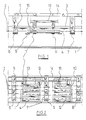
- the electrolysis apparatus in accordance with figure 1 basically comprises an elongate tank or channel 1 as electrolyte bath.
- This bath 1 is filled with a suitable electrolyte up to level 3 so that both the anodes 4 and the cathodes 5 are immersed in it.
- the cathode pins 5 are fixed on successive supporting arms 6, 7, 8 (e.g. of copper).
- the successive anode sections 9, 10 are mounted between said supporting arms. Said sections comprise the supporting arms 11 (e.g. of copper) for the anode plates 4, 12. These are e.g. inert lead anodes.
- the respective supporting arms for cathodes and anodes are connected to the current-supply bars 13 and 14.
- the electrode-supporting parts (6, 7, 8) of these arms are immersed with the electrodes 5 in bath 1 under the bath surface 3.
- the electrolyte can be continuously circulated by means of pumps (not shown) and through the bores 16 in the anode plates towards the surface level 3 of the bath 1.
- the circulation increases the turbulence in the bath, which increases the electrolysis efficiency.
- the wire-shaped objects 2 to be coated are now continuously conducted past a succession of anodes 4, 12 and cathode supports 6, 7, 8 below the electrolyte surface 3.
- the wires drag against the pins 5 fixed on the respective current-carrying supporting arms 6, 7, 8 as a result of which they are connected as cathode, tracing a horizontal zigzag path of travel as shown in figure 2. So, the successive peaks and valleys of the zigzag path of travel are located at these pins 5.
- the electrodes themselves comprise a highly conductive but preferably also wear-resistant metal alloy, e.g. tungsten carbide at the sliding contacts at the zigzag peak/valley positions.
- the wires come in the vicinity of the inert anode plates 4, 12 where the desired metal deposition from the bath 1 takes place.
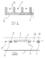
- the anode plates 4, 12 can be designed flat but will preferably comprise channel-shaped recesses 15 (as sketched in figure 3) at the path of travel of the wires 2 between two consecutive cathode pins 5. This way, a more even metal deposition is obtained over the whole wire circumference.
- Figure 4 schematically shows another nearly horizontal zigzag path of travel for the wires 2.
- An insulated (ceramic) counterpressure bar 17 or 18 is mounted near each cathode-supporting arm 6 or 7 respectively. These can e.g. be tilted upwards out of and away from the bath for the purpose of making the bath surface easily accessible when starting the apparatus for a new series of wires.
- the cathode-supporting arms 6, 7 are each coated with a wear-resistant layer 19 as sliding contact for the transmission of current to the wires.
Landscapes
- Chemical & Material Sciences (AREA)
- Engineering & Computer Science (AREA)
- Chemical Kinetics & Catalysis (AREA)
- Electrochemistry (AREA)
- Materials Engineering (AREA)
- Metallurgy (AREA)
- Organic Chemistry (AREA)
- Electroplating Methods And Accessories (AREA)
- Coating With Molten Metal (AREA)
Applications Claiming Priority (2)
| Application Number | Priority Date | Filing Date | Title |
|---|---|---|---|
| BE8801152 | 1988-10-06 | ||
| BE8801152A BE1001859A3 (nl) | 1988-10-06 | 1988-10-06 | Inrichting voor het continu electrolytisch behandelen van draadvormige voorwerpen. |
Publications (2)
| Publication Number | Publication Date |
|---|---|
| EP0362924A1 EP0362924A1 (en) | 1990-04-11 |
| EP0362924B1 true EP0362924B1 (en) | 1994-05-11 |
Family
ID=3883667
Family Applications (1)
| Application Number | Title | Priority Date | Filing Date |
|---|---|---|---|
| EP89202386A Expired - Lifetime EP0362924B1 (en) | 1988-10-06 | 1989-09-21 | Apparatus for the continuous electrolytic treatment of wire-shaped objects |
Country Status (9)
| Country | Link |
|---|---|
| EP (1) | EP0362924B1 (ja) |
| JP (1) | JP2859672B2 (ja) |
| KR (1) | KR0174269B1 (ja) |
| AU (1) | AU610759B2 (ja) |
| BE (1) | BE1001859A3 (ja) |
| BR (1) | BR8907111A (ja) |
| DE (1) | DE68915236T2 (ja) |
| ES (1) | ES2056196T3 (ja) |
| WO (1) | WO1990004050A1 (ja) |
Families Citing this family (2)
| Publication number | Priority date | Publication date | Assignee | Title |
|---|---|---|---|---|
| GB9309521D0 (en) * | 1993-05-08 | 1993-06-23 | United Wire Ltd | Improved method |
| IT201700065757A1 (it) * | 2017-06-14 | 2018-12-14 | Assembling S R L | Apparecchio di trattamento filo metallico, elettrolitico od elettrochimico e cella elettrolitica utilizzata |
Family Cites Families (3)
| Publication number | Priority date | Publication date | Assignee | Title |
|---|---|---|---|---|
| US2229423A (en) * | 1937-05-18 | 1941-01-21 | Purdue Research Foundation | Electroplating apparatus for wire or the like |
| BE517552A (ja) * | 1951-05-17 | |||
| FR2609292B1 (fr) * | 1987-01-06 | 1989-03-24 | Pechiney Aluminium | Procede et dispositif pour deposer electrolytiquement au defile un film continu de nickel sur du fil metallique a usage electrique |
-
1988
- 1988-10-06 BE BE8801152A patent/BE1001859A3/nl not_active IP Right Cessation
-
1989
- 1989-09-21 AU AU42135/89A patent/AU610759B2/en not_active Ceased
- 1989-09-21 EP EP89202386A patent/EP0362924B1/en not_active Expired - Lifetime
- 1989-09-21 JP JP1509306A patent/JP2859672B2/ja not_active Expired - Lifetime
- 1989-09-21 WO PCT/EP1989/001093 patent/WO1990004050A1/en unknown
- 1989-09-21 ES ES89202386T patent/ES2056196T3/es not_active Expired - Lifetime
- 1989-09-21 DE DE68915236T patent/DE68915236T2/de not_active Expired - Fee Related
- 1989-09-21 KR KR1019900701208A patent/KR0174269B1/ko not_active IP Right Cessation
- 1989-09-21 BR BR898907111A patent/BR8907111A/pt not_active IP Right Cessation
Also Published As
| Publication number | Publication date |
|---|---|
| JP2859672B2 (ja) | 1999-02-17 |
| BR8907111A (pt) | 1991-02-05 |
| JPH03502715A (ja) | 1991-06-20 |
| EP0362924A1 (en) | 1990-04-11 |
| AU610759B2 (en) | 1991-05-23 |
| AU4213589A (en) | 1990-05-01 |
| KR0174269B1 (ko) | 1999-02-18 |
| KR920700311A (ko) | 1992-02-19 |
| BE1001859A3 (nl) | 1990-03-20 |
| WO1990004050A1 (en) | 1990-04-19 |
| ES2056196T3 (es) | 1994-10-01 |
| DE68915236T2 (de) | 1994-08-18 |
| DE68915236D1 (de) | 1994-06-16 |
Similar Documents
| Publication | Publication Date | Title |
|---|---|---|
| US6238529B1 (en) | Device for electrolytic treatment of printed circuit boards and conductive films | |
| US6071400A (en) | Method and device for the electrochemical treatment with treatment liquid of an item to be treated | |
| US4395320A (en) | Apparatus for producing electrodeposited wires | |
| US2431065A (en) | Continuous wire and strip electro-processing machine | |
| EP0248118A1 (en) | Metallurgical structure control of electrodeposits using ultrasonic agitation | |
| US4097342A (en) | Electroplating aluminum stock | |
| US3300396A (en) | Electroplating techniques and anode assemblies therefor | |
| US2454935A (en) | Continuous wire and strip electroprocessing machine | |
| JPH04263096A (ja) | 金属箔に表面処理を施すための方法および装置 | |
| GB2071155A (en) | Electrolytically treating a metal strip | |
| KR20010023152A (ko) | 처리할 물품상의 전기적 접촉점상의 금속층의 두께를균일화하기 위한 장치 및 방법 | |
| JP4521146B2 (ja) | 電気絶縁の箔材料の表面上で電気的に互いに絶縁された導電性構造を電解処理するための方法及び装置並びに上記方法の使用法 | |
| KR100487646B1 (ko) | 금속띠판의전해산세척방법및장치 | |
| US4828653A (en) | Long lasting anode for high current density galvanization | |
| EP0362924B1 (en) | Apparatus for the continuous electrolytic treatment of wire-shaped objects | |
| US5478457A (en) | Apparatus for the continuous electrolytic treatment of wire-shaped objects | |
| JP2549557B2 (ja) | 電解処理装置 | |
| US3869371A (en) | Electrotinning wire | |
| US2725355A (en) | Apparatus for electropolishing metallic articles | |
| KR960004269B1 (ko) | 금속스트립의 무흠집 전기도금방법 | |
| US3947344A (en) | Inert anode | |
| JPS6393892A (ja) | 電気メツキライン通電ロ−ルの研摩装置 | |
| US4721554A (en) | Electroplating apparatus | |
| KR790001163B1 (ko) | 금속스트립, 특히 강스트립의 수평직선형 도금방법 | |
| KR850000790B1 (ko) | 전기도금 와이어의 제조장치 |
Legal Events
| Date | Code | Title | Description |
|---|---|---|---|
| PUAI | Public reference made under article 153(3) epc to a published international application that has entered the european phase |
Free format text: ORIGINAL CODE: 0009012 |
|
| AK | Designated contracting states |
Kind code of ref document: A1 Designated state(s): BE DE ES FR GB IT LU NL |
|
| 17P | Request for examination filed |
Effective date: 19901006 |
|
| 17Q | First examination report despatched |
Effective date: 19920121 |
|
| GRAA | (expected) grant |
Free format text: ORIGINAL CODE: 0009210 |
|
| AK | Designated contracting states |
Kind code of ref document: B1 Designated state(s): BE DE ES FR GB IT LU NL |
|
| REF | Corresponds to: |
Ref document number: 68915236 Country of ref document: DE Date of ref document: 19940616 |
|
| EPTA | Lu: last paid annual fee | ||
| ITF | It: translation for a ep patent filed |
Owner name: SOCIETA' ITALIANA BREVETTI S.P.A. |
|
| ET | Fr: translation filed | ||
| ITTA | It: last paid annual fee | ||
| REG | Reference to a national code |
Ref country code: ES Ref legal event code: FG2A Ref document number: 2056196 Country of ref document: ES Kind code of ref document: T3 |
|
| PLBE | No opposition filed within time limit |
Free format text: ORIGINAL CODE: 0009261 |
|
| STAA | Information on the status of an ep patent application or granted ep patent |
Free format text: STATUS: NO OPPOSITION FILED WITHIN TIME LIMIT |
|
| 26N | No opposition filed | ||
| PGFP | Annual fee paid to national office [announced via postgrant information from national office to epo] |
Ref country code: NL Payment date: 19960617 Year of fee payment: 8 |
|
| PG25 | Lapsed in a contracting state [announced via postgrant information from national office to epo] |
Ref country code: NL Free format text: LAPSE BECAUSE OF NON-PAYMENT OF DUE FEES Effective date: 19980401 |
|
| NLV4 | Nl: lapsed or anulled due to non-payment of the annual fee |
Effective date: 19980401 |
|
| PGFP | Annual fee paid to national office [announced via postgrant information from national office to epo] |
Ref country code: LU Payment date: 20010618 Year of fee payment: 13 |
|
| PGFP | Annual fee paid to national office [announced via postgrant information from national office to epo] |
Ref country code: ES Payment date: 20011009 Year of fee payment: 13 |
|
| REG | Reference to a national code |
Ref country code: GB Ref legal event code: IF02 |
|
| PG25 | Lapsed in a contracting state [announced via postgrant information from national office to epo] |
Ref country code: LU Free format text: LAPSE BECAUSE OF NON-PAYMENT OF DUE FEES Effective date: 20020921 |
|
| PG25 | Lapsed in a contracting state [announced via postgrant information from national office to epo] |
Ref country code: ES Free format text: LAPSE BECAUSE OF NON-PAYMENT OF DUE FEES Effective date: 20020922 |
|
| REG | Reference to a national code |
Ref country code: ES Ref legal event code: FD2A Effective date: 20031011 |
|
| PGFP | Annual fee paid to national office [announced via postgrant information from national office to epo] |
Ref country code: FR Payment date: 20050607 Year of fee payment: 17 |
|
| PG25 | Lapsed in a contracting state [announced via postgrant information from national office to epo] |
Ref country code: IT Free format text: LAPSE BECAUSE OF NON-PAYMENT OF DUE FEES;WARNING: LAPSES OF ITALIAN PATENTS WITH EFFECTIVE DATE BEFORE 2007 MAY HAVE OCCURRED AT ANY TIME BEFORE 2007. THE CORRECT EFFECTIVE DATE MAY BE DIFFERENT FROM THE ONE RECORDED. Effective date: 20050921 |
|
| PGFP | Annual fee paid to national office [announced via postgrant information from national office to epo] |
Ref country code: BE Payment date: 20060608 Year of fee payment: 18 |
|
| PGFP | Annual fee paid to national office [announced via postgrant information from national office to epo] |
Ref country code: DE Payment date: 20060609 Year of fee payment: 18 |
|
| PGFP | Annual fee paid to national office [announced via postgrant information from national office to epo] |
Ref country code: GB Payment date: 20060831 Year of fee payment: 18 |
|
| REG | Reference to a national code |
Ref country code: FR Ref legal event code: ST Effective date: 20070531 |
|
| BERE | Be: lapsed |
Owner name: S.A. *BEKAERT N.V. Effective date: 20070930 |
|
| PG25 | Lapsed in a contracting state [announced via postgrant information from national office to epo] |
Ref country code: FR Free format text: LAPSE BECAUSE OF NON-PAYMENT OF DUE FEES Effective date: 20061002 |
|
| GBPC | Gb: european patent ceased through non-payment of renewal fee |
Effective date: 20070921 |
|
| PG25 | Lapsed in a contracting state [announced via postgrant information from national office to epo] |
Ref country code: DE Free format text: LAPSE BECAUSE OF NON-PAYMENT OF DUE FEES Effective date: 20080401 |
|
| PG25 | Lapsed in a contracting state [announced via postgrant information from national office to epo] |
Ref country code: BE Free format text: LAPSE BECAUSE OF NON-PAYMENT OF DUE FEES Effective date: 20070930 |
|
| PG25 | Lapsed in a contracting state [announced via postgrant information from national office to epo] |
Ref country code: GB Free format text: LAPSE BECAUSE OF NON-PAYMENT OF DUE FEES Effective date: 20070921 |