EP0362766B1 - Control device for an ophthalmological treatment apparatus - Google Patents
Control device for an ophthalmological treatment apparatus Download PDFInfo
- Publication number
- EP0362766B1 EP0362766B1 EP19890118232 EP89118232A EP0362766B1 EP 0362766 B1 EP0362766 B1 EP 0362766B1 EP 19890118232 EP19890118232 EP 19890118232 EP 89118232 A EP89118232 A EP 89118232A EP 0362766 B1 EP0362766 B1 EP 0362766B1
- Authority
- EP
- European Patent Office
- Prior art keywords
- hand
- finger
- control arrangement
- practitioner
- fact
- Prior art date
- Legal status (The legal status is an assumption and is not a legal conclusion. Google has not performed a legal analysis and makes no representation as to the accuracy of the status listed.)
- Expired - Lifetime
Links
Images

Classifications
-
- A—HUMAN NECESSITIES
- A61—MEDICAL OR VETERINARY SCIENCE; HYGIENE
- A61B—DIAGNOSIS; SURGERY; IDENTIFICATION
- A61B3/00—Apparatus for testing the eyes; Instruments for examining the eyes
- A61B3/0075—Apparatus for testing the eyes; Instruments for examining the eyes provided with adjusting devices, e.g. operated by control lever
Definitions
- the present invention relates to a device for controlling an ophthalmological treatment apparatus, said apparatus comprising at least one power laser beam having a focal point of concentration of said beam capable of acting, on the firing order of a practitioner, at a determined location in the eye of a patient, location defined by first, second and third orthogonal dimensional coordinates, said control device comprising a housing on which a hand of a practitioner can rest, said housing being provided first means for fixing the focal point according to the first coordinate, second means for fixing the focal point in a plane according to the second and third coordinates and third means for triggering the laser shot when said three coordinates are reached, said first, second and third means being arranged in such a way that they can each be controlled by the fingers of the same hand.
- the device essentially comprises a first light source which emits a power laser beam intended for treatment proper and a second light source which emits a beam of visible coherent light of low power arranged to envelop the power beam.
- the beams mentioned then pass through a converging lens which concentrates them in a focal point which is the processing point, the visible light beam being present to allow to locate with precision the place where is the focus of the power beam.
- the focal point is observed by a practitioner through an eyepiece (or binocular) while the ocular cavity is illuminated by an auxiliary source of light. When the desired location for treatment is reached, the practitioner controls the laser shot.
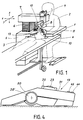
- the devices of the prior art are presented in broad outline as shown in FIG. 1.
- the treatment device comprises a table 1 in front of which a practitioner sits 2.
- a patient 3 On the other side of the table takes a patient 3, here lying on a bed 4 precisely fitting into the table.
- the patient is seated and rests his head on a chin rest attached to the table.
- the device is designed so that the patient's head is immobilized relative to said device.
- Figure 1 also shows a box 5 which supports the table.
- This support generally contains the sources giving rise to the beams of power and visible light which were discussed above.
- These beams are conveyed inside the patient's eye by a column 6 and a movable arm 7, the latter carrying an exit optic 8 capable of focusing the beams at a point which is to be brought to a very precise place in the patient's eye, a point which is observed by the practitioner through the binocular 9.
- the arm 7 can move according to the three orthogonal coordinates X, Y and Z.
- control device 13 comprises four separate members respectively controlling the displacements X, Y and Z and the laser shot, the first three members being able to be rollers than it operates in both directions and the fourth member can be a simple push button.
- This provision is inconvenient because it forces the practitioner to memorize the location of the rollers and the functions assigned to them with the risk of error or loss of time that such a system can result, since the practitioner's view is entirely occupied with observing the cavity of the eye to be treated and must not be distracted to check, for example, whether the correct control member is actuated.
- the present invention is characterized either by the fact that the first and second means are a ball capable of being respectively pressed and rolled by a first finger and that the third means is a pusher capable to be pressed by a second finger, either by the fact that the first means is a roulette capable of being turned by a first finger, that the second means is a ball capable of being rolled by a second finger and that the third medium is a pusher capable of being pressed by a third finger.
- a control device associating a ball with a computer keyboard is shown in document GB-A-2 154 306. In this document it is not indicated that the ball can be pressed or associated with a wheel to fix the point focal according to a first coordinate.
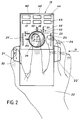
- the device 13 is a housing on which has been shown a hand of a practitioner.
- the device is provided with a first means for fixing the focal point of the laser beam according to a first coordinate.
- the figure shows that this first means here is a roller 20 which can be turned by a first finger 21, in this case the thumb of the right hand 22.
- Figure 2 also shows that the device is provided with a second means for fixing the focal point of the laser beam in a plane according to second and third coordinates.
- This second means is here a ball 23 capable of being rolled by a second finger 24, ie the index finger of the right hand 22.
- FIG. 2 shows that the device comprises a third means for triggering the laser shot as soon as said three contact details have been reached by actuation of the first and second means.
- This third means is here in the form of a pusher 25 capable of being actuated by a third finger 26, ie the middle finger of the right hand 22.
- a third finger 26 ie the middle finger of the right hand 22.
- the first, second and third means are arranged in such a way that they can each be controlled by a finger different from the same hand.
- the device uses only two fingers to bring the focal point of the beam to the desired location and this thanks to the use of a single means (the ball) to position the focal point in a plane.
- the use of the index to search for two co-ordinates in a plane is particularly advantageous because, on the one hand, of the excellent mobility that this finger presents in comparison with the mobility of the other fingers of the hand and, on the other hand, the independence of action of this finger in relation to the others.
- the use of the thumb for the search for a single coordinate is also judicious, this finger being less mobile, but lending itself well to the rolling action that it is asked to perform on the roulette.
- the use of the middle finger for laser shooting is advantageous especially because of its position well suited to actuate a push button.
- FIG. 2 shows that the caster 20 and the pusher 25 are split by a second caster 20 ′ and a second pusher 25 ′.
- This arrangement allows the control device to be used also with the left hand as shown in FIG. 3.
- the left hand 22 ′ by its thumb 21 ′, its index finger 24 ′ and its middle finger 26 ′ respectively controls the wheel 20 ′, ball 23 and pusher 25 ′.
- Figure 3 the same advantageous arrangement of controls, also arranged quite logically but for the left hand this time.
- FIG. 4 is a view according to the arrow IV of FIG. 2, we find on the device 13 the same three control means which have been described above, that is to say -to say in order the roulette 20 ′, the ball 23 and the pusher 25.
- This view also shows an additional feature of the invention which consists in breaking the face against which the hand comes to rest in a first rising zone 30 capable of serving as a support for the wrist of the hand and in a second descending zone 31 on which are arranged the ball 23 and the pushers 25, 25 ′ controlled respectively by the index and middle finger of the hand (not shown here) .
- This broken face device is particularly well suited for supporting the hand and contributes, if we add the judicious arrangement of the controls themselves, to a particularly well chosen ergonomics, facilitating rapid action, free from error and reducing the both physical and intellectual fatigue.
- Figures 2, 3 and 4 show that the control device may further comprise fourth means for quickly reaching an area in the environment close to where the shooting is to take place. They are in fact pushers allowing a rough preset according to the three coordinates.
- the pushers 40 and 41 allow a rapid search for the first coordinate. The same goes for pushers 42, 43 and 44, 45 which allow the same quick search, but for the second and third coordinates, respectively.
- the means to move the focal point in a plane using a single finger here consists in using a ball which can roll freely around its center.
- a ball which can roll freely around its center.
- the use of a joystick poses problems of position stability and accuracy.
- FIG. 2 shows that the ball has been assigned the coordinates X and Y.
- the ball 23 drives two wheels 50, 54 arranged orthogonally to one another .
- the figure shows that the wheel 50 drives a disc 51.
- This disc is pierced with slots which allow the light emitted by a lamp 52.
- On the other side of the disc is a photoelectric sensor which receives light passing through the slits.
- the electrical pulses from the sensor control a power electronics which in turn controls, for example, a stepping motor.
- This motor controls the arm 7 of the ophthalmological device shown in FIG. 1 and this according to the Y coordinate.
- a similar device is used for moving the arm according to the X coordinate, starting from the wheel 54.
- the Z coordinate is controlled by the thumb 21 acting on the caster 20.
- the angle of rotation of the caster can also be converted into electrical pulses as explained above.
- the ball system able to move a point in a plane is known today and is used for example in some personal computers (PC).
- PC personal computers
- the system is reversed compared to that described here, that is to say that it is not a finger which moves the ball, but the hand which moves the case on a table, the ball being under the housing and rolling when the housing is moved.
- This system is commonly called “mouse” and is described in particular in the review “Mini & Micros", No. 305 / June 22, 1988.
- Logimouse marketed by Logitech SA, CH-1143 Apples.
- the mouse system has the disadvantage of requiring a lot of space for the excursion of the case on the table and getting dirty quickly.
- the ball 23 described here is used to move the focal point in an XY plane. We can see, however, that it could also be used to move this point along the Z coordinate. This additional function can easily be fulfilled, if we add to the ball a possibility of sinking which can act on a contact, itself putting in operation an arm drive motor in the Z coordinate. In these conditions, a single finger of the hand is sufficient to control the arm in three directions, the index 24, 24 ′ for example. In these conditions also, the firing function can be fulfilled either by the thumb 21, 21 ′, or by the middle finger 26, 26 ′.
- the description which has just been made is based on a treatment device where the patient is lying.
- the movement controlled by the ball is then carried out in a plane perpendicular to the vertical. If the patient is seated, it will be understood that the movement controlled by the ball must be done in a plane parallel to the vertical.
- the control device will be equipped, if necessary, with a system of permutation of the coordinates.
Description
La présente invention est relative à un dispositif de commande d'un appareil de traitement ophtalmologique, ledit appareil comportant au moins un faisceau laser de puissance présentant un point focal de concentration dudit faisceau susceptible d'agir, sur l'ordre de tir d'un praticien, à un endroit déterminé de l'oeil d'un patient, endroit défini par des première, deuxième et troisième coordonnées dimensionnelles orthogonales, ledit dispositif de commande comprenant un boîtier sur lequel peut reposer une main d'un praticien, ledit boîtier étant pourvu d'un premier moyen pour fixer le point focal selon la première coordonnée, d'un second moyen pour fixer le point focal dans un plan selon les deuxième et troisième coordonnées et d'un troisième moyen pour déclencher le tir laser quand lesdites trois coordonnées sont atteintes, lesdits premier, deuxième et troisième moyens étant arrangés de telle manière qu'ils puissent être commandés chacun par les doigts de la même main.The present invention relates to a device for controlling an ophthalmological treatment apparatus, said apparatus comprising at least one power laser beam having a focal point of concentration of said beam capable of acting, on the firing order of a practitioner, at a determined location in the eye of a patient, location defined by first, second and third orthogonal dimensional coordinates, said control device comprising a housing on which a hand of a practitioner can rest, said housing being provided first means for fixing the focal point according to the first coordinate, second means for fixing the focal point in a plane according to the second and third coordinates and third means for triggering the laser shot when said three coordinates are reached, said first, second and third means being arranged in such a way that they can each be controlled by the fingers of the same hand.
Un appareil de traitement ophtalmologique dont il s'agit d'assurer la commande est décrit par exemple dans le document EP-B-0 030 210. L'appareil comporte essentiellement une première source de lumière qui émet un faisceau laser de puissance destiné au traitement proprement dit et une seconde source de lumière qui émet un faisceau de lumière cohérente visible de faible puissance arrangé pour envelopper le faisceau de puissance. Les faisceaux mentionnés passent alors à travers une lentille convergente qui les concentre en un point focal qui est le point de traitement, le faisceau de lumière visible étant présent pour permettre de localiser avec précision l'endroit où se trouve le foyer du faisceau de puissance. Le point de focalisation est observé par un praticien à travers un oculaire (ou un binoculaire) alors que la cavité oculaire est éclairée par une source auxiliaire de lumière. Lorsque l'endroit recherché pour le traitement est atteint, le praticien commande le tir laser.An ophthalmological treatment device which is to be controlled is described for example in document EP-B-0 030 210. The device essentially comprises a first light source which emits a power laser beam intended for treatment proper and a second light source which emits a beam of visible coherent light of low power arranged to envelop the power beam. The beams mentioned then pass through a converging lens which concentrates them in a focal point which is the processing point, the visible light beam being present to allow to locate with precision the place where is the focus of the power beam. The focal point is observed by a practitioner through an eyepiece (or binocular) while the ocular cavity is illuminated by an auxiliary source of light. When the desired location for treatment is reached, the practitioner controls the laser shot.
Les appareils de l'art antérieur se présentent dans les grandes lignes comme montré en figure 1. L'appareil de traitement comporte une table 1 devant laquelle est assis un praticien 2. De l'autre côté de la table prend place un patient 3, ici couché sur un lit 4 venant s'encastrer avec précision dans la table. Dans certains cas, le patient est assis et repose sa tête sur une mentonnière fixée à la table. Quelle que soit la position choisie pour le patient, l'appareil est conçu pour que la tête du patient soit immobilisée par rapport audit appareil.The devices of the prior art are presented in broad outline as shown in FIG. 1. The treatment device comprises a table 1 in front of which a practitioner sits 2. On the other side of the table takes a
La figure 1 montre encore un coffret 5 qui supporte la table. Ce support contient généralement les sources donnant naissance aux faisceaux de puissance et de lumière visible dont il a été question ci-dessus. Ces faisceaux sont acheminés à l'intérieur de l'oeil du patient par une colonne 6 et un bras mobile 7, ce dernier portant une optique de sortie 8 susceptible de focaliser les faisceaux en un point qu'il s'agit d'amener à un endroit bien précis de l'oeil du patient, point qui est observé par le praticien à travers le binoculaire 9. Dans ce but, le bras 7 peut se mouvoir selon les trois coordonnées orthogonales X, Y et Z.Figure 1 also shows a
Pour dévier les faisceaux sortant de l'optique 8 et les diriger à un point précis de la cavité oculaire, le praticien se sert d'un verre de contact 10 qu'il tient sur l'oeil du patient. Dans ce cas, sa main gauche 11 est occupée. La main droite 12 du praticien doit donc pouvoir à elle seule actionner un dispositif de commande 13, qui n'est pas décrit dans le document cité plus haut, et qui doit permettre la commande d'au moins quatre fonctions : celles du déplacement de la colonne 7 selon trois coordonnées X, Y et Z et celle du tir laser au moment où les trois coordonnées recherchées sont atteintes. On pourrait imaginer, sans que cela fasse preuve d'une activité inventive quelconque, que le dispositif de commande 13 comporte quatre organes distincts commandant respectivement les déplacements X, Y et Z et le tir laser, les trois premiers organes pouvant être des roulettes qu'on actionne dans les deux sens et le quatrième organe pouvant être un simple bouton-poussoir. Cette disposition est mal commode car elle oblige le praticien à mémoriser l'emplacement des roulettes et les fonctions qui leur sont dévolues avec les risques d'erreur ou de pertes de temps qu'un tel système peut entraîner, puisque la vue du praticien est entièrement occupée à observer la cavité de l'oeil à soigner et ne doit pas être distraite pour vérifier, par exemple, si le bon organe de commande est actionné.To deflect the beams leaving the
Aussi, pour éviter les inconvénients énumérés ci-dessus, la présente invention est caractérisée soit par le fait que les premier et deuxième moyens sont une boule susceptible d'être respectivement enfoncée et roulée par un premier doigt et que le troisième moyen est un poussoir susceptible d'être enfoncé par un deuxième doigt, soit par le fait que le premier moyen est une roulette susceptible d'être tournée par un premier doigt, que le second moyen est une boule susceptible d'être roulée par un deuxième doigt et que le troisième moyen est un poussoir susceptible d'être enfoncé par un troisième doigt.Also, to avoid the drawbacks listed above, the present invention is characterized either by the fact that the first and second means are a ball capable of being respectively pressed and rolled by a first finger and that the third means is a pusher capable to be pressed by a second finger, either by the fact that the first means is a roulette capable of being turned by a first finger, that the second means is a ball capable of being rolled by a second finger and that the third medium is a pusher capable of being pressed by a third finger.
Un dispositif de commande associant une boule à un clavier d'ordinateur est montré dans le document GB-A-2 154 306. Dans ce document il n'est pas indiqué que la boule puisse être pressée ou associée à une roulette pour fixer le point focal selon une première coordonnée.A control device associating a ball with a computer keyboard is shown in document GB-A-2 154 306. In this document it is not indicated that the ball can be pressed or associated with a wheel to fix the point focal according to a first coordinate.
L'invention sera expliquée maintenant en se référant au dessin annexé qui l'illustre à titre d'exemple et dans lequel :
- La figure 1 montre en perspective un appareil de traitement ophtalmologique qui utilise un dispositif de commande selon l'invention.
- La figure 2 est une vue de dessus du dispositif de commande selon l'invention, desservi par la main droite d'un praticien droitier.
- La figure 3 est une vue de dessus du dispositif de commande selon l'invention, desservi par la main gauche d'un praticien gaucher.
- La figure 4 est une vue latérale du dispositif selon l'invention et selon la flèche IV de la figure 2.
- Figure 1 shows in perspective an ophthalmic treatment apparatus which uses a control device according to the invention.
- Figure 2 is a top view of the control device according to the invention, served by the right hand of a right-handed practitioner.
- Figure 3 is a top view of the control device according to the invention, served by the left hand of a left-handed practitioner.
- FIG. 4 is a side view of the device according to the invention and according to arrow IV of FIG. 2.
L'appareil de traitement ophtalmologique de la figure 1 a été décrit ci-dessus comme faisant partie de l'état de la technique. Cet appareil est commandé au moyen d'un dispositif 13 original qui va être décrit aux figures 2, 3 et 4.The ophthalmic treatment apparatus of Figure 1 has been described above as part of the state of the art. This device is controlled by means of an
Comme on le voit sur la figure 2, le dispositif 13 est un boîtier sur lequel a été représenté une main d'un praticien. Le dispositif est pourvu d'un premier moyen pour fixer le point focal du faisceau laser selon une première coordonnée. La figure montre que ce premier moyen est ici une roulette 20 qui peut être tournée par un premier doigt 21, en l'occurence le pouce de la main droite 22. La figure 2 montre encore que le dispositif est pourvu d'un second moyen pour fixer le point focal du faisceau laser dans un plan selon des deuxième et troisième coordonnées. Ce deuxième moyen est ici une boule 23 susceptible d'être roulée par un deuxième doigt 24, soit l'index de la main droite 22. Enfin la figure 2 montre que le dispositif comporte un troisième moyen pour déclencher le tir laser dès que lesdites trois coordonnées ont été atteintes par l'actionnement des premier et deuxième moyens. Ce troisième moyen se présente ici sous la forme d'un poussoir 25 susceptible d'être actionné par un troisième doigt 26, soit le majeur de la main droite 22. Tout à fait généralement, on s'aperçoit que les premier, deuxième et troisième moyens sont arrangés de telle manière qu'ils puissent être commandés chacun par un doigt différent de la même main.As seen in Figure 2, the
On constate que le dispositif n'utilise que deux doigts pour amener le point focal du faisceau à l'endroit désiré et ceci grâce à l'utilisation d'un seul moyen (la boule) pour positionner le point focal dans un plan. L'utilisation de l'index pour assurer la recherche de deux coorodonnées dans un plan est particulièrement avantageuse à cause, d'une part, de l'excellente mobilité que présente ce doigt en comparaison de la mobilité des autres doigts de la main et, d'autre part, de la faculté d'indépendance d'action de ce doigt par rapport aux autres. L'utilisation du pouce pour la recherche d'une seule coordonnée est aussi judicieuse, ce doigt étant moins mobile, mais se prêtant bien à l'action de roulement qu'on lui demande d'effectuer sur la roulette. Enfin, l'utilisation du majeur pour le tir laser est avantageuse surtout du fait de sa position bien adaptée à actionner un bouton-poussoir.It can be seen that the device uses only two fingers to bring the focal point of the beam to the desired location and this thanks to the use of a single means (the ball) to position the focal point in a plane. The use of the index to search for two co-ordinates in a plane is particularly advantageous because, on the one hand, of the excellent mobility that this finger presents in comparison with the mobility of the other fingers of the hand and, on the other hand, the independence of action of this finger in relation to the others. The use of the thumb for the search for a single coordinate is also judicious, this finger being less mobile, but lending itself well to the rolling action that it is asked to perform on the roulette. Finally, the use of the middle finger for laser shooting is advantageous especially because of its position well suited to actuate a push button.
Si l'on attribue à la première coordonnée, la fixation du point focal par rapport à la profondeur de l'oeil et aux deuxième et troisième coordonnées, la fixation du point focal dans un plan parallèle à la face du patient, on aura de plus une suite logique d'actions entreprises d'abord par le pouce, puis par l'index et enfin par le majeur lorsque les deux premiers doigts se seront fixés dans une position pour laquelle le tir peut avoir lieu, cette suite logique correspondant au rang logique qu'occupent le pouce, l'index et le majeur composant une main.If we attribute to the first coordinate, the fixing of the focal point relative to the depth of the eye and to the second and third coordinates, the fixing of the focal point in a plane parallel to the face of the patient, we will have more a logical sequence of actions undertaken first by the thumb, then by the index finger and finally by the middle finger when the first two fingers are fixed in a position for which the shot can take place, this logical sequence corresponding to the logical rank occupied by the thumb, index and middle fingers of a hand.
La figure 2 montre que la roulette 20 et le poussoir 25 sont dédoublés par une seconde roulette 20′ et un second poussoir 25′. Cette disposition permet d'utiliser le dispositif de commande également avec la main gauche comme cela est représenté en figure 3. En figure 3, la main gauche 22′ par son pouce 21′, son index 24′ et son majeur 26′ commande respectivement la roulette 20′, la boule 23 et le poussoir 25′. On retrouve en figure 3 la même disposition avantageuse des commandes, disposées également de façon toute logique mais pour la main gauche cette fois-ci.Figure 2 shows that the
Si l'on se réfère maintenant à la figure 4, qui est une vue selon la flèche IV de la figure 2, on retrouve sur le dispositif 13 les mêmes trois moyens de commande qui ont été décrits ci-dessus, c'est-à-dire dans l'ordre la roulette 20′, la boule 23 et le poussoir 25. Cette vue montre en outre une particularité supplémentaire de l'invention qui consiste à briser la face contre laquelle la main vient s'appuyer en une première zone montante 30 susceptible de servir d'appui au poignet de la main et en une seconde zone descendante 31 sur laquelle sont disposés la boule 23 et les poussoirs 25, 25′ commandés respectivement par l'index et le majeur de la main (non représentée ici). Cette dispositif en face brisée est particulièrement bien adaptée à l'appui de la main et contribue, si on y ajoute la disposition judicieuse des commandes proprement dites, à une ergonomie particulièrement bien choisie, facilitant une action rapide, dépourvue d'erreur et réduisant la fatigue tant physique qu'intellectuelle.If we now refer to FIG. 4, which is a view according to the arrow IV of FIG. 2, we find on the
Les figures 2, 3 et 4 montrent que le dispositif de commande peut comporter en outre des quatrièmes moyens pour atteindre rapidement une zone se trouvant dans l'environnement proche de l'endroit où le tir doit avoir lieu. Il s'agit en fait de poussoirs permettant un préréglage grossier selon les trois coordonnées. Dans les figures, les poussoirs 40 et 41 permettent une recherche rapide de la première coordonnée. Il en va de même pour les poussoirs 42, 43 et 44, 45 qui permettent la même recherche rapide, mais pour les deuxième et troisième coordonnées, respectivement.Figures 2, 3 and 4 show that the control device may further comprise fourth means for quickly reaching an area in the environment close to where the shooting is to take place. They are in fact pushers allowing a rough preset according to the three coordinates. In the figures, the
Le moyen pour déplacer dans un plan le point focal à l'aide d'un seul doigt consiste ici à utiliser une boule qui peut rouler librement autour de son centre. On pourrait envisager d'autres moyens par exemple l'utilisation d'un manche à balai, appelé communément "joy-stick" à la place de la boule. L'utilisation d'un joy-stick pose cependant des problèmes de stabilité de position et de précision.The means to move the focal point in a plane using a single finger here consists in using a ball which can roll freely around its center. We could consider other means for example the use of a broomstick, commonly called "joy-stick" instead of the ball. The use of a joystick, however, poses problems of position stability and accuracy.
La figure 2 montre qu'on a affecté à la boule les coordonnées X et Y. De façon généralement connue de l'état de la technique, la boule 23 entraîne deux roues 50, 54 disposées orthogonalement l'une par rapport à l'autre. La figure montre que la roue 50 entraîne un disque 51. Ce disque est percé de fentes qui laissent passer la lumière émise par une lampe 52. De l'autre côté du disque se trouve un capteur photoélectrique qui reçoit la lumière traversant les fentes. Les impulsions électriques issues du capteur commandent une électronique de puissance qui commande à son tour, par exemple, un moteur pas à pas. Ce moteur commande le bras 7 de l'appareil ophtalmologique montré en figure 1 et cela selon la coordonnée Y. Un dispositif semblable est mis en oeuvre pour le déplacement du bras selon la coordonnée X, à partir de la roue 54. La coordonnée Z est commandée par le pouce 21 agissant sur la roulette 20. L'angle de rotation de la roulette peut aussi être converti en impulsions électriques comme expliqué ci-dessus.FIG. 2 shows that the ball has been assigned the coordinates X and Y. In a manner generally known from the prior art, the
Le système de boule apte à déplacer un point dans un plan est connu aujourd'hui et est utilisé par exemple dans certains ordinateurs personnels (PC). Dans cette application, le système est inversé par rapport à celui décrit ici, c'est-à-dire que ce n'est pas un doigt qui déplace la boule, mais la main qui promène le boîtier sur une table, la boule se trouvant sous le boîtier et roulant quand on déplace le boîtier. Ce système est appelé communément "souris" et est décrit notamment dans la revue "Mini & Micros", No 305 / 22 juin 1988. On en trouve une réalisation sous la marque déposée "Logimouse" commercialisée par Logitech SA, CH-1143 Apples. Le système souris présente cependant l'inconvénient de demander beaucoup de place pour l'excursion du boîtier sur la table et de se salir rapidement. De plus, on conçoit qu'il est plus difficile d'immobiliser toute la main qu'un seul doigt de cette main quand la position de point focal est trouvée, surtout si un autre doigt doit encore commander une roulette (coordonnée Z). On ajoutera que le système proposé dans l'invention permet d'atteindre très rapidement le point recherché et ceci avec une précision élevée et un effort moins grand.The ball system able to move a point in a plane is known today and is used for example in some personal computers (PC). In this application, the system is reversed compared to that described here, that is to say that it is not a finger which moves the ball, but the hand which moves the case on a table, the ball being under the housing and rolling when the housing is moved. This system is commonly called "mouse" and is described in particular in the review "Mini & Micros", No. 305 / June 22, 1988. There is an embodiment under the registered trademark "Logimouse" marketed by Logitech SA, CH-1143 Apples. The mouse system has the disadvantage of requiring a lot of space for the excursion of the case on the table and getting dirty quickly. In addition, it is understood that it is more difficult to immobilize the whole hand than a single finger of this hand when the focal point position is found, especially if another finger still has to control a wheel (Z coordinate). It will be added that the system proposed in the invention makes it possible to reach the point sought very quickly and this with high precision and less effort.
La boule 23 décrite ici est utilisée pour déplacer le point focal dans un plan XY. On conçoit cependant qu'elle pourrait également servir à déplacer ce point selon la coordonnée Z. Cette fonction supplémentaire peut facilement être remplie, si l'on adjoint à la boule une possibilité d'enfoncement qui peut agir sur un contact, lui-même mettant en marche un moteur d'entraînement du bras selon la coordonnée Z. Dans ces conditions, un seul doigt de la main suffit à commander le bras dans les trois directions, l'index 24, 24′ par exemple. Dans ces conditions également, la fonction de tir peut être remplie soit par le pouce 21, 21′, soit par le majeur 26, 26′.The
La description qui vient d'être faite se base sur un appareil de traitement où le patient est couché. Le déplacement commandé par la boule est réalisé alors dans un plan perpendiculaire à la verticale. Si le patient est assis, on comprendra que le déplacement commandé par la boule devra se faire dans un plan parallèle à la verticale. Pour cela le dispositif de commande sera équipé, si nécessaire, d'un système de permutation des coordonnées.The description which has just been made is based on a treatment device where the patient is lying. The movement controlled by the ball is then carried out in a plane perpendicular to the vertical. If the patient is seated, it will be understood that the movement controlled by the ball must be done in a plane parallel to the vertical. For this, the control device will be equipped, if necessary, with a system of permutation of the coordinates.
Claims (8)
- Control arrangement (13) for an apparatus for ophtalmological treatment, said apparatus including at least one laser power beam having a focal point of concentration of said beam capable of acting when fired by a practitioner (2) on a predetermined location within the eye of a patient (3), said location being defined by first, second and third dimensional orthogonal coordinates, said control arrangement comprising a casing on which a hand (22, 22') of a practitioner may rest, said casing being provided with a first means for fixing the focal point according to the first coordinate, a second means for fixing the focal point within a plane according to the second and third coordinates and a third means for releasing the laser beam when said three coordinates are reached, said means being arranged in a manner such they may each be controlled by the fingers of the same hand, characterized by the fact that the first and second means comprise a ball (23) adapted to be respectively pressed in and rolled by a first finger and that the third means is a push button (25, 25') adapted to be pressed in by a second finger.
- Control arrangement according to claim 1, characterized by the fact that the first, second and third means are arranged in a manner such that they may be controlled respectively by the index finger (24, 24') and the thumb (21, 21') or the middle finger (26, 26') of the hand of the practitioner.
- Control arrangement (13) for an apparatus for ophtalmological treatment, said apparatus including at least one laser power beam having a focal point of concentration of said beam capable of acting when fired by a practitioner (2) on a predetermined location within the eye of a patient (3), said location being defined by first, second and third dimensional orthogonal coordinates, said control arrangement comprising a casing on which a hand (22, 22') of a practitioner may rest, said casing being provided with a first means for fixing the focal point according to the first coordinate, a second means for fixing the focal point within a plane according to the second and third coordinates and a third means for releasing the laser beam when said three coordinates are reached, said means being arranged in a manner such they may each be controlled by the fingers of the same hand, characterized by the fact that the first means is a roller (20, 20') adapted to be rotated by a first finger, that the second means is a ball (23) adapted to be rolled by a second finger and that the third means is a push button (25, 25') adapted to be pressed in by a third finger.
- Control arrangement according to claim 3, characterized by the fact that the first, second and third means are arranged in a manner such that they may be controlled respectively by the thumb (21, 21'), the index finger (24, 24') and the middle finger (26, 26') of the hand of the practitioner.
- Control arrangement according to claim 1 or claim 3, characterized by the fact that it further comprises fourth means (40 to 45) for rapidly reaching a zone within the surroundings close to the location where release of the laser beam is to take place.
- Control arrangement according to claim 1 or claim 3, characterized by the fact that said first, second and third means are arranged in a manner such that they may be indifferently controlled by the right hand (22) or the left hand (22') of the practitioner.
- Control arrangement according to claim 4, characterized by the fact that the casing has the form of a parallelepiped which on the face on which the hand may rest exhibits a ball (23) which may be rolled by the index finger of the hand in order to fix the second and third coordinates and two push buttons (25, 25') located on either side of the ball so as to control firing of the laser beam by the middle finger of the hand, said casing exhibiting on each of its lateral faces a roller (20, 20') adapted to be rotated by the thumb of the hand in order to fix the first coordinate.
- Control arrangement according to claim 7, characterized by the fact that said face is broken and exhibits a first rising zone (30) adapted to serve as a wrist support for the hand and a second falling zone (31) on which are arranged the ball and the two push buttons.
Priority Applications (1)
| Application Number | Priority Date | Filing Date | Title |
|---|---|---|---|
| AT89118232T ATE99145T1 (en) | 1988-10-06 | 1989-10-02 | ADJUSTMENT DEVICE FOR AN OPHTHALMOLOGICAL TREATMENT DEVICE. |
Applications Claiming Priority (4)
| Application Number | Priority Date | Filing Date | Title |
|---|---|---|---|
| CH3744/88A CH676420A5 (en) | 1988-10-06 | 1988-10-06 | |
| CH3744/88 | 1988-10-06 | ||
| FR8813402A FR2637704B1 (en) | 1988-10-10 | 1988-10-10 | DEVICE FOR CONTROLLING AN OPHTHALMOLOGICAL TREATMENT APPARATUS |
| FR8813402 | 1988-10-10 |
Publications (2)
| Publication Number | Publication Date |
|---|---|
| EP0362766A1 EP0362766A1 (en) | 1990-04-11 |
| EP0362766B1 true EP0362766B1 (en) | 1993-12-29 |
Family
ID=25693753
Family Applications (1)
| Application Number | Title | Priority Date | Filing Date |
|---|---|---|---|
| EP19890118232 Expired - Lifetime EP0362766B1 (en) | 1988-10-06 | 1989-10-02 | Control device for an ophthalmological treatment apparatus |
Country Status (2)
| Country | Link |
|---|---|
| EP (1) | EP0362766B1 (en) |
| DE (1) | DE68911824T2 (en) |
Family Cites Families (4)
| Publication number | Priority date | Publication date | Assignee | Title |
|---|---|---|---|---|
| US4470320A (en) * | 1981-11-12 | 1984-09-11 | Wico Corporation | Joystick assembly with wear member |
| FR2524298A1 (en) * | 1982-04-01 | 1983-10-07 | Essilor Int | LASER OPHTHALMOLOGICAL SURGICAL APPARATUS |
| CH655809A5 (en) * | 1984-02-16 | 1986-05-15 | Depraz S A | DEVICE FOR INTRODUCING GRAPHIC DATA INTO A CALCULATOR. |
| DE3601022A1 (en) * | 1986-01-16 | 1987-07-23 | Zeiss Carl Fa | Device for the fine adjustment in all three spatial directions of an instrument arranged on a base |
-
1989
- 1989-10-02 EP EP19890118232 patent/EP0362766B1/en not_active Expired - Lifetime
- 1989-10-02 DE DE1989611824 patent/DE68911824T2/en not_active Expired - Fee Related
Also Published As
| Publication number | Publication date |
|---|---|
| DE68911824T2 (en) | 1994-07-28 |
| EP0362766A1 (en) | 1990-04-11 |
| DE68911824D1 (en) | 1994-02-10 |
Similar Documents
| Publication | Publication Date | Title |
|---|---|---|
| CH676420A5 (en) | ||
| EP0074289B1 (en) | Joy-stick for electronic games | |
| EP0091334B1 (en) | Apparatus for surgical treatment of the eyes using a laser beam | |
| FR2876813A1 (en) | VIDEO PLAY CONTROL DEVICE WITH INTEGRATED GARBAGE BALL CONTROL MEMBER. | |
| EP2364757A1 (en) | Method and device for remote control of a drone, in particular a rotary-wing drone | |
| EP0362766B1 (en) | Control device for an ophthalmological treatment apparatus | |
| FR3081438A1 (en) | MONOBLOC AND REMOVABLE PEDAL MODULE FOR AIRCRAFT SPOILER. | |
| FR2637704A1 (en) | Device for controlling an ophthalmological treatment apparatus | |
| EP0044770B1 (en) | Objective refractometer provided with a microcomputer | |
| WO1987006478A1 (en) | Systematized treatment instrument, using particularly laser energy, useful for example in dermatology | |
| EP0395478B1 (en) | Automatic pupillometer entirely static | |
| FR2463606A1 (en) | DEVICE FOR CONTROLLING THE PHORIE OF AN INDIVIDUAL IN VISION RECONCILED | |
| EP1424710B1 (en) | Control device for at least two functions of an element and/or at least two different parts of an element | |
| WO2014072168A1 (en) | Inertia or balance setting of a hairspring-balance assembly for a timepiece | |
| FR2859420A1 (en) | COCKPIT OF A MOTOR VEHICLE WITH A WHEEL AND WITH AN ADJUSTABLE SEAT | |
| FR2594686A1 (en) | Laser incision appts. providing straight lines around iris - has alignment and focussing effected by reflecting optics and power beam which is superimposed with pulse from high power beam | |
| WO2021089474A1 (en) | Articulation having three degrees of freedom for a robot, and corresponding control method | |
| LU82274A1 (en) | LASER CUTTING METHOD AND APPARATUS FOR IMPLEMENTING THE METHOD | |
| EP0478872A1 (en) | Festoon-sewing machine with a device for automatically positioning a pattern-cam | |
| EP0321342A1 (en) | Inertial stabilizing device for the inclination of orientable elements and telescope mirror mounted on this device | |
| WO2019092386A1 (en) | Gesture-based control system for actuators | |
| FR2787763A1 (en) | Helicopter pilot control stick command recentering assistance mechanism having stick position detector calculation unit information passing and relative position calculating/ pilot display mechanism position adjustment showing | |
| EP0311485A1 (en) | Servo controlled device for optical reading of and magnetic writing on an information carrier | |
| FR2590687A1 (en) | EPISCOPE WITH INCORPORATED VISUALIZATION SYSTEM. | |
| CH718619A2 (en) | Watch fitted with a control device allowing the stroke of a previously interrupted hand to be restarted. |
Legal Events
| Date | Code | Title | Description |
|---|---|---|---|
| PUAI | Public reference made under article 153(3) epc to a published international application that has entered the european phase |
Free format text: ORIGINAL CODE: 0009012 |
|
| AK | Designated contracting states |
Kind code of ref document: A1 Designated state(s): AT BE DE GB IT LU NL SE |
|
| 17P | Request for examination filed |
Effective date: 19900615 |
|
| 17Q | First examination report despatched |
Effective date: 19921103 |
|
| RAP1 | Party data changed (applicant data changed or rights of an application transferred) |
Owner name: HAAG-STREIT AG |
|
| GRAA | (expected) grant |
Free format text: ORIGINAL CODE: 0009210 |
|
| AK | Designated contracting states |
Kind code of ref document: B1 Designated state(s): AT BE DE GB IT LU NL SE |
|
| PG25 | Lapsed in a contracting state [announced via postgrant information from national office to epo] |
Ref country code: IT Free format text: LAPSE BECAUSE OF FAILURE TO SUBMIT A TRANSLATION OF THE DESCRIPTION OR TO PAY THE FEE WITHIN THE PRESCRIBED TIME-LIMIT;WARNING: LAPSES OF ITALIAN PATENTS WITH EFFECTIVE DATE BEFORE 2007 MAY HAVE OCCURRED AT ANY TIME BEFORE 2007. THE CORRECT EFFECTIVE DATE MAY BE DIFFERENT FROM THE ONE RECORDED. Effective date: 19931229 Ref country code: SE Effective date: 19931229 Ref country code: AT Effective date: 19931229 Ref country code: NL Effective date: 19931229 |
|
| REF | Corresponds to: |
Ref document number: 99145 Country of ref document: AT Date of ref document: 19940115 Kind code of ref document: T |
|
| REF | Corresponds to: |
Ref document number: 68911824 Country of ref document: DE Date of ref document: 19940210 |
|
| GBT | Gb: translation of ep patent filed (gb section 77(6)(a)/1977) |
Effective date: 19940322 |
|
| NLV1 | Nl: lapsed or annulled due to failure to fulfill the requirements of art. 29p and 29m of the patents act | ||
| PG25 | Lapsed in a contracting state [announced via postgrant information from national office to epo] |
Ref country code: LU Free format text: LAPSE BECAUSE OF NON-PAYMENT OF DUE FEES Effective date: 19941031 Ref country code: BE Effective date: 19941031 |
|
| PLBE | No opposition filed within time limit |
Free format text: ORIGINAL CODE: 0009261 |
|
| STAA | Information on the status of an ep patent application or granted ep patent |
Free format text: STATUS: NO OPPOSITION FILED WITHIN TIME LIMIT |
|
| 26N | No opposition filed | ||
| BERE | Be: lapsed |
Owner name: HAAG-STREIT A.G. Effective date: 19941031 |
|
| PGFP | Annual fee paid to national office [announced via postgrant information from national office to epo] |
Ref country code: GB Payment date: 19980925 Year of fee payment: 10 |
|
| PGFP | Annual fee paid to national office [announced via postgrant information from national office to epo] |
Ref country code: DE Payment date: 19981028 Year of fee payment: 10 |
|
| PG25 | Lapsed in a contracting state [announced via postgrant information from national office to epo] |
Ref country code: GB Free format text: LAPSE BECAUSE OF NON-PAYMENT OF DUE FEES Effective date: 19991002 |
|
| GBPC | Gb: european patent ceased through non-payment of renewal fee |
Effective date: 19991002 |
|
| PG25 | Lapsed in a contracting state [announced via postgrant information from national office to epo] |
Ref country code: DE Free format text: LAPSE BECAUSE OF NON-PAYMENT OF DUE FEES Effective date: 20000801 |