EP0362757A2 - Rotary machine of the screw pump type - Google Patents
Rotary machine of the screw pump type Download PDFInfo
- Publication number
- EP0362757A2 EP0362757A2 EP89118212A EP89118212A EP0362757A2 EP 0362757 A2 EP0362757 A2 EP 0362757A2 EP 89118212 A EP89118212 A EP 89118212A EP 89118212 A EP89118212 A EP 89118212A EP 0362757 A2 EP0362757 A2 EP 0362757A2
- Authority
- EP
- European Patent Office
- Prior art keywords
- rotors
- chamber
- wall
- casing
- rotor
- Prior art date
- Legal status (The legal status is an assumption and is not a legal conclusion. Google has not performed a legal analysis and makes no representation as to the accuracy of the status listed.)
- Granted
Links
Images
Classifications
-
- F—MECHANICAL ENGINEERING; LIGHTING; HEATING; WEAPONS; BLASTING
- F16—ENGINEERING ELEMENTS AND UNITS; GENERAL MEASURES FOR PRODUCING AND MAINTAINING EFFECTIVE FUNCTIONING OF MACHINES OR INSTALLATIONS; THERMAL INSULATION IN GENERAL
- F16H—GEARING
- F16H57/00—General details of gearing
- F16H57/04—Features relating to lubrication or cooling or heating
- F16H57/0412—Cooling or heating; Control of temperature
- F16H57/0415—Air cooling or ventilation; Heat exchangers; Thermal insulations
-
- F—MECHANICAL ENGINEERING; LIGHTING; HEATING; WEAPONS; BLASTING
- F04—POSITIVE - DISPLACEMENT MACHINES FOR LIQUIDS; PUMPS FOR LIQUIDS OR ELASTIC FLUIDS
- F04C—ROTARY-PISTON, OR OSCILLATING-PISTON, POSITIVE-DISPLACEMENT MACHINES FOR LIQUIDS; ROTARY-PISTON, OR OSCILLATING-PISTON, POSITIVE-DISPLACEMENT PUMPS
- F04C29/00—Component parts, details or accessories of pumps or pumping installations, not provided for in groups F04C18/00 - F04C28/00
- F04C29/04—Heating; Cooling; Heat insulation
-
- F—MECHANICAL ENGINEERING; LIGHTING; HEATING; WEAPONS; BLASTING
- F16—ENGINEERING ELEMENTS AND UNITS; GENERAL MEASURES FOR PRODUCING AND MAINTAINING EFFECTIVE FUNCTIONING OF MACHINES OR INSTALLATIONS; THERMAL INSULATION IN GENERAL
- F16H—GEARING
- F16H57/00—General details of gearing
- F16H57/04—Features relating to lubrication or cooling or heating
- F16H57/042—Guidance of lubricant
- F16H57/0421—Guidance of lubricant on or within the casing, e.g. shields or baffles for collecting lubricant, tubes, pipes, grooves, channels or the like
-
- F—MECHANICAL ENGINEERING; LIGHTING; HEATING; WEAPONS; BLASTING
- F16—ENGINEERING ELEMENTS AND UNITS; GENERAL MEASURES FOR PRODUCING AND MAINTAINING EFFECTIVE FUNCTIONING OF MACHINES OR INSTALLATIONS; THERMAL INSULATION IN GENERAL
- F16H—GEARING
- F16H57/00—General details of gearing
- F16H57/04—Features relating to lubrication or cooling or heating
- F16H57/0467—Elements of gearings to be lubricated, cooled or heated
- F16H57/0469—Bearings or seals
Definitions
- the present invention relates to a rotary machine of the screw pump type.
- These machines are driven by a motor and have a significant flow rate, greater than 50 m3 / h and rotate at speeds greater than 10,000 rpm. They are capable of sucking from atmospheric pressure to a pressure of 10 ⁇ 2 mbar. At a suction pressure between 200 and 300 mbar, they absorb a high power which is completely dissipated in heat. As the thermal masses and the thermal dissipations of the rotor and the stator are very different, it is necessary to put significant clearances between the rotors and the stator in order to avoid seizures. This results in a poor quality flow-pressure characteristic.
- the object of the present invention is to improve the flow-pressure characteristic by taking measures making it possible to reduce the clearances between rotors and stator.
- the subject of the invention is therefore a rotary machine of the screw pump type comprising a first rotor and a second rotor, with combined screws, supported by bearings inside a casing-stator enveloping the rotors and provided with a suction inlet communicating with the cavity in which the rotors are located at one of their ends and a discharge outlet communicating with this cavity at the other end of the rotors, the first rotor being driven in rotation by a motor drive and the second rotor being driven in rotation by means of a synchronization gear located in a first chamber of said casing, comprised between said motor and one end of said rotors, said synchronization gear bathed in a lubricating fluid, characterized in that the housing cavity containing said rotors is separated from said first chamber containing said gear by a first wall traversed by the shafts of said rotors through seals, in that at the end of the rotors, opposite the side comprising said gear, the shafts of the
- said casing-stator comprises a third chamber situated between said second wall and a third wall enclosing the rotors laterally and traversed by the rotor shafts through seals, bearings supporting the rotors being disposed in one or the other of the second and third walls between the seals, an auxiliary pipe connecting said first chamber to said third chamber, said fluid circulation channels of the rotors having on the one hand outlets orifices in said third chamber, and on the other hand orifices terminating between support bearings for the rotors, mounted in said first wall, and said gaskets for crossing the shafts of the rotors through this said first wall.
- two temperature probes are installed inside the stator housing, one of which is arranged as close as possible to the rotors, the two probes being connected to a control box producing a control signal used for the control of an adjustable valve located in said pipe provided with pumping means.
- the rotary machine is cooled and the temperatures of the casing-stator and of the rotors are equalized, which allows to keep small clearances, favorable to a good pressure-flow characteristic.
- the rotary machine shown which is in this case, a screw pump, dry, vacuum, comprises a first rotor 1 and a second rotor 2 with conjugated screws. These two rotors are mounted inside a casing-stator 3 which envelops them and in which they are supported by ball bearings 4, 5 for the first rotor 1 and 6, 7 for the second rotor 2.
- the shaft 8 of the first rotor 1 passes through the end of the stator casing 3 through a seal 9 and is driven in rotation by a drive motor 10.
- the second rotor 2 is driven in rotation via a synchronization gear comprising a pinion 11 mounted on the shaft 8 and a pinion 12 mounted on the shaft 13 of the second rotor 2.
- the synchronization gear 11-12 is located in the casing 3 inside a first chamber 14 containing a lubrication liquid 15.
- This first chamber 14 is separated from the part of the cavity 30 of the casing containing the two rotors 1 and 2, by a first partition 16 which carries the bearings 4 and 6. Seals 17 and 18 are arranged in this first partition 16 at the crossing of the shafts 8 and 13.
- the shafts 8 and 13 of the rotors successively pass through a third wall 19 and a second wall 20 delimiting between them two, a third chamber 21.
- a second chamber 31 being delimited between the second wall 20 and the end of the casing-stator.
- the third wall 19 laterally encloses the rotors 1 and 2 and it is crossed by the shafts 8 and 13 through seals 22 and 23.
- the second wall 20 is crossed by the shafts 8 and 13 through seals 24 and 25.
- the rolling bearings 5 and 7 are mounted in the second wall 20 between the seals 22 and 24 for the shaft 8 and between the seals 23 and 25 for the shaft 13.
- the rolling bearings 4 and 6 are mounted in the first partition between the seals 17, 18 and the first chamber 14.
- the casing-stator 3 is provided with a suction inlet 26 which communicates with the internal cavity 30 of the casing-stator through the third partition 19 and with a discharge outlet 27 which communicates with the internal cavity 30 of the casing- stator 3 through the first partition 16.
- the third chamber 21 communicates with the first chamber 14 by an auxiliary pipe 28 and the lubrication and cooling fluid 15 located in these two chambers is sucked by a circulation pump 47, located in a main pipe 29, and discharged into the second chamber 31 and from there into channels of circulation 32 of the stator and 33, 34 of the rotors.
- the circulation channel 32 of the stator ends at the other end of the machine in the first chamber 14 or, as shown in the drawing, directly in the auxiliary pipe 28, or main pipe 29, on the suction side.
- the circulation channels 33 and 34 of the rotors have discharge orifices 35 and 36 ending directly in the first chamber 14, orifices 37 and 38 ending in the third chamber 21 and projecting lubricating liquid onto the bearings 5 and 7 and finally orifices 39 and 40, for the lubrication of bearings 4 and 6, located between seals 17-18 and bearings 4-6.
- the main pipe 29 includes a heat exchanger 41 cooled by a water circuit 42.
- Two temperature probes 43 and 44 are installed inside the stator housing 3, one of which, the probe 44, is placed as close as possible to the rotors 1 and 2, so as to measure the temperatures of the stator and the rotors .
- a control box 45 to which they are connected produces a control signal for the flow of the lubricating-coolant fluid 15 as a function of the difference in temperatures measured by the probes 43 and 44, this signal controlling the operation of a flow control valve. 46 located in the main pipeline 29.
- This insulation 48 has the additional advantage of ensuring sound insulation.
Abstract
Description
La présente invention concerne une machine rotative du type pompe à vis.The present invention relates to a rotary machine of the screw pump type.
Ces machines sont entraînées par un moteur et elles ont un débit important, supérieur à 50 m³/h et tournent à des vitesses supérieures à 10000 t/mm. Elles sont capables d'aspirer depuis la pression atmosphérique jusqu'à une pression de 10⁻² mbar. A une pression d'aspiration comprise entre 200 et 300 mbar, elles absorbent une puissance élevée qui est entièrement dissipée en chaleur. Comme les masses thermiques et les dissipations thermiques du rotor et du stator sont très différentes, on doit mettre des jeux importants entre les rotors et le stator de façon à éviter les grippages. Il en résulte une caractéristique débit-pression de mauvaise qualité.These machines are driven by a motor and have a significant flow rate, greater than 50 m³ / h and rotate at speeds greater than 10,000 rpm. They are capable of sucking from atmospheric pressure to a pressure of 10⁻² mbar. At a suction pressure between 200 and 300 mbar, they absorb a high power which is completely dissipated in heat. As the thermal masses and the thermal dissipations of the rotor and the stator are very different, it is necessary to put significant clearances between the rotors and the stator in order to avoid seizures. This results in a poor quality flow-pressure characteristic.
La présente invention a pour but d'améliorer la caractéristique débit-pression en prenant des mesures permettant de diminuer les jeux entre rotors et stator.The object of the present invention is to improve the flow-pressure characteristic by taking measures making it possible to reduce the clearances between rotors and stator.
L' invention a ainsi pour objet une machine rotative du type pompe à vis comprenant un premier rotor et un second rotor, à vis conjuguées, supportés par des paliers à l'intérieur d'un carter-stator enveloppant les rotors et muni d'une entrée d'aspiration communiquant avec la cavité dans laquelle sont situés les rotors à l'une de leurs extrémités et d'une sortie de refoulement communiquant avec cette cavité à l'autre extrémité des rotors, le premier rotor étant entraîné en rotation par un moteur d'entraînement et le deuxième rotor étant entraîné en rotation par l'intermédiaire d'un engrenage de synchronisation situé dans une première chambre dudit carter, comprise entre ledit moteur et une extrémité desdits rotors, ledit engrenage de synchronisation baignant dans un fluide lubrifiant, caractérisé en ce que la cavité du carter contenant lesdits rotors est séparée de ladite première chambre contenant ledit engrenage par une première paroi traversée par les arbres desdits rotors à travers des joints d'étanchéité, en ce qu'à l'extrémité des rotors, opposée au côté comportant ledit engrenage, les arbres des rotors traversent une seconde paroi à travers des joints d'étanchéité, et en ce que ledit carter comporte, au delà de cette seconde paroi, une seconde chambre reliée à ladite première chambre par une canalisation principale munie de moyens de pompage, les rotors et le carter-stator comportant des canaux de circulation de fluide aboutissant d'une part dans ladite seconde chambre et d'autre part dans ladite première chambre et/ou dans ladite canalisation dans sa portion située entre lesdits moyens de pompage et ladite première chambre, un échangeur de chaleur étant disposé sur le parcours de ladite canalisation pour le refroidissement dudit fluide lubrifiant.The subject of the invention is therefore a rotary machine of the screw pump type comprising a first rotor and a second rotor, with combined screws, supported by bearings inside a casing-stator enveloping the rotors and provided with a suction inlet communicating with the cavity in which the rotors are located at one of their ends and a discharge outlet communicating with this cavity at the other end of the rotors, the first rotor being driven in rotation by a motor drive and the second rotor being driven in rotation by means of a synchronization gear located in a first chamber of said casing, comprised between said motor and one end of said rotors, said synchronization gear bathed in a lubricating fluid, characterized in that the housing cavity containing said rotors is separated from said first chamber containing said gear by a first wall traversed by the shafts of said rotors through seals, in that at the end of the rotors, opposite the side comprising said gear, the shafts of the rotors pass through a second wall through seals, and in that said casing comprises, beyond this second wall, a second chamber connected to said first chamber by a main pipe provided with pumping means, the rotors and the casing-stator comprising fluid circulation channels ending on the one hand in said second chamber and on the other hand in said first chamber and / or in said pipe in its portion located between said pumping means and said first chamber, a heat exchanger being arranged on the path of said pipe for the cooling of said lubricating fluid.
Selon une réalisation préférée de l'invention, ledit carter-stator comporte une troisième chambre située entre ladite seconde paroi et une troisième paroi enfermant latéralement les rotors et traversée par les arbres des rotors à travers des joints d'étanchéité, des paliers supports des rotors étant disposés dans l'une ou l'autre des seconde et troisième parois entre les joints d'étanchéité, une canalisation auxiliaire reliant ladite première chambre à ladite troisième chambre, lesdits canaux de circulation de fluide des rotors ayant d'une part des orifices aboutissant dans ladite troisième chambre, et d'autre part des orifices aboutissant entre des paliers support des rotors, montés dans ladite première paroi, et lesdits joints d'étanchéité de traversée des arbres des rotors à travers cette dite première paroi.According to a preferred embodiment of the invention, said casing-stator comprises a third chamber situated between said second wall and a third wall enclosing the rotors laterally and traversed by the rotor shafts through seals, bearings supporting the rotors being disposed in one or the other of the second and third walls between the seals, an auxiliary pipe connecting said first chamber to said third chamber, said fluid circulation channels of the rotors having on the one hand outlets orifices in said third chamber, and on the other hand orifices terminating between support bearings for the rotors, mounted in said first wall, and said gaskets for crossing the shafts of the rotors through this said first wall.
Selon une autre caractéristique, deux sondes de température sont installées à l'intérieur du carter-stator, dont l'une est disposée le plus proche possible des rotors, les deux sondes étant reliées à un coffret de commande élaborant un signal de commande utilisé pour la commande d'une vanne réglable située dans ladite canalisation munie de moyens de pompage.According to another characteristic, two temperature probes are installed inside the stator housing, one of which is arranged as close as possible to the rotors, the two probes being connected to a control box producing a control signal used for the control of an adjustable valve located in said pipe provided with pumping means.
Ainsi, par les dispositions de l'invention, on refroidit la machine rotative et on égalise les températures du carter-stator et des rotors, ce qui permet de conserver des jeux faibles, favorables à une bonne caractéristique pression-débit.Thus, by the provisions of the invention, the rotary machine is cooled and the temperatures of the casing-stator and of the rotors are equalized, which allows to keep small clearances, favorable to a good pressure-flow characteristic.
On va maintenant donner la description d'un exemple de mise en oeuvre de l'invention en se référant au dessin annexé dans lequel :
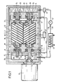
- La figure 1 est une vue schématique en coupe axiale d'une pompe à vis à vide, sèche, selon l'invention.
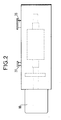
- La figure 2 est une vue extérieure en élévation.
- Figure 1 is a schematic view in axial section of a dry vacuum screw pump according to the invention.
- Figure 2 is an exterior elevational view.
En se référant aux figures jointes, la machine rotative représentée, qui est dans le cas présent, une pompe à vis, sèche, à vide, comprend un premier rotor 1 et un second rotor 2 à vis conjuguées. Ces deux rotors sont montés à l'intérieur d'un carter-stator 3 qui les enveloppe et dans lequel ils sont supportés par des roulements à billes 4, 5 pour le premier rotor 1 et 6, 7 pour le second rotor 2.Referring to the attached figures, the rotary machine shown, which is in this case, a screw pump, dry, vacuum, comprises a first rotor 1 and a second rotor 2 with conjugated screws. These two rotors are mounted inside a casing-stator 3 which envelops them and in which they are supported by
L'arbre 8 du premier rotor 1 traverse l'extrémité du carter-stator 3 à travers un joint d'étanchéité 9 et est entraîné en rotation par un moteur d'entraînement 10. Le second rotor 2 est entraîné en rotation par l'intermédiaire d'un engrenage de synchronisation comprenant un pignon 11 monté sur l'arbre 8 et un pignon 12 monté sur l'arbre 13 du second rotor 2.The
L'engrenage de synchronisation 11-12 est situé dans le carter 3 à l'intérieur d'une première chambre 14 contenant un liquide de lubrification 15. Cette première chambre 14 est séparée de la partie de la cavité 30 du carter contenant les deux rotors 1 et 2, par une première cloison 16 qui porte les roulements 4 et 6. Des joints d'étanchéité 17 et 18 sont disposés dans cette première cloison 16 à la traversée des arbres 8 et 13. A l'autre extrémité, les arbres 8 et 13 des rotors traversent successivement une troisième paroi 19 et une seconde paroi 20 délimitant entre elles deux, une troisième chambre 21. Une seconde chambre 31 étant délimitée entre la seconde paroi 20 et l'extrémité du carter-stator. La troisième paroi 19 enferme latéralement les rotors 1 et 2 et elle est traversée par les arbres 8 et 13 à travers des joints d'étanchéité 22 et 23. De même, la seconde paroi 20 est traversée par les arbres 8 et 13 à travers des joints d'étanchéité 24 et 25. Les paliers à roulement 5 et 7 sont montés dans la seconde paroi 20 entre les joints 22 et 24 pour l'arbre 8 et entre les joints 23 et 25 pour l'arbre 13. De même, à l'extrémité opposée, les paliers à roulement 4 et 6 sont montés dans la première cloison entre les joints 17, 18 et la première chambre 14.The synchronization gear 11-12 is located in the casing 3 inside a
Le carter-stator 3 est muni d'une entrée d'aspiration 26 qui communique avec la cavité interne 30 du carter-stator à travers la troisième cloison 19 et d'une sortie de refoulement 27 qui communique avec la cavité interne 30 du carter-stator 3 à travers la première cloison 16. La troisième chambre 21 communique avec la première chambre 14 par une canalisation auxiliaire 28 et le fluide de lubrification et de refroidissement 15 situé dans ces deux chambres est aspiré par une pompe de circulation 47, située dans une canalisation principale 29, et refoulé dans la seconde chambre 31 et de là dans des canaux de circulation 32 du stator et 33, 34 des rotors. Le canal de circulation 32 du stator aboutit à l'autre extrémité de la machine dans la première chambre 14 ou, comme cela est représenté sur le dessin, directement dans la canalisation auxiliaire 28, ou principale 29, du côté de l'aspiration. Les canaux de circulation 33 et 34 des rotors ont des orifices d'évacuation 35 et 36 aboutissant directement dans la première chambre 14, des orifices 37 et 38 aboutissant dans la troisième chambre 21 et projetant du liquide lubrifiant sur les roulements 5 et 7 et enfin des orifices 39 et 40, pour la lubrification des roulements 4 et 6, situés entre les joints 17-18 et les roulements 4-6. La canalisation principale 29 comprend un échangeur de chaleur 41 refroidi par un circuit d'eau 42.The casing-stator 3 is provided with a
Deux sondes de température 43 et 44 sont installées à l'intérieur du carter-stator 3 dont l'une, la sonde 44, est disposée le plus près possible des rotors 1 et 2, de façon à mesurer les températures du stator et des rotors. Un coffret de commande 45 auquel elles sont reliées élabore un signal de commande de débit du fluide lubrifiant-réfrigérant 15 en fonction de la différence des températures mesurées par les sondes 43 et 44, ce signal commandant la manoeuvre d'une vanne de réglage de débit 46 située dans la canalisation principale 29.Two
Pour mieux uniformiser la température de la pompe à vide, l'ensemble du carter-stator 3 est enfermé dans un matériau calorifuge 48. Ce calorifuge 48 a l'avantage supplémentaire d'assurer une isolation phonique.To better standardize the temperature of the vacuum pump, the entire casing-stator 3 is enclosed in an insulation material 48. This insulation 48 has the additional advantage of ensuring sound insulation.
Claims (3)
Priority Applications (1)
| Application Number | Priority Date | Filing Date | Title |
|---|---|---|---|
| AT89118212T ATE93010T1 (en) | 1988-10-07 | 1989-10-02 | SCREW PUMP TYPE ROTARY LOBE MACHINE. |
Applications Claiming Priority (2)
| Application Number | Priority Date | Filing Date | Title |
|---|---|---|---|
| FR8813193A FR2637655B1 (en) | 1988-10-07 | 1988-10-07 | SCREW PUMP TYPE ROTARY MACHINE |
| FR8813193 | 1988-10-07 |
Publications (3)
| Publication Number | Publication Date |
|---|---|
| EP0362757A2 true EP0362757A2 (en) | 1990-04-11 |
| EP0362757A3 EP0362757A3 (en) | 1990-04-18 |
| EP0362757B1 EP0362757B1 (en) | 1993-08-11 |
Family
ID=9370801
Family Applications (1)
| Application Number | Title | Priority Date | Filing Date |
|---|---|---|---|
| EP89118212A Expired - Lifetime EP0362757B1 (en) | 1988-10-07 | 1989-10-02 | Rotary machine of the screw pump type |
Country Status (7)
| Country | Link |
|---|---|
| US (1) | US4983106A (en) |
| EP (1) | EP0362757B1 (en) |
| JP (1) | JPH02149791A (en) |
| AT (1) | ATE93010T1 (en) |
| DE (1) | DE68908323T2 (en) |
| ES (1) | ES2042922T3 (en) |
| FR (1) | FR2637655B1 (en) |
Cited By (4)
| Publication number | Priority date | Publication date | Assignee | Title |
|---|---|---|---|---|
| EP0577936A1 (en) * | 1992-07-09 | 1994-01-12 | PKL Verpackungssysteme GmbH | Pump |
| WO1999019630A1 (en) * | 1997-10-10 | 1999-04-22 | Leybold Vakuum Gmbh | Cooled screw vacuum pump |
| WO1999019631A1 (en) * | 1997-10-10 | 1999-04-22 | Leybold Vakuum Gmbh | Screw vacuum pump provided with rotors |
| WO2020078689A1 (en) * | 2018-10-17 | 2020-04-23 | Pfeiffer Vacuum | Method for controlling the temperature of a vacuum pump, and associated vacuum pump and installation |
Families Citing this family (43)
| Publication number | Priority date | Publication date | Assignee | Title |
|---|---|---|---|---|
| JP2572566Y2 (en) * | 1991-07-05 | 1998-05-25 | 株式会社 神戸製鋼所 | Air-cooled oil-free screw compressor |
| US5626470A (en) * | 1996-04-10 | 1997-05-06 | Ingersoll-Rand Company | Method for providing lubricant to thrust bearing |
| WO1999035402A1 (en) * | 1997-12-30 | 1999-07-15 | Ateliers Busch S.A. | Cooling device |
| DE19800825A1 (en) * | 1998-01-02 | 1999-07-08 | Schacht Friedrich | Dry compacting screw pump |
| DE19963170A1 (en) * | 1999-12-27 | 2001-06-28 | Leybold Vakuum Gmbh | Vacuum pump with shaft sealant |
| US6394777B2 (en) * | 2000-01-07 | 2002-05-28 | The Nash Engineering Company | Cooling gas in a rotary screw type pump |
| FR2812040B1 (en) * | 2000-07-18 | 2003-02-07 | Cit Alcatel | MONOBLOCK HOUSING FOR VACUUM PUMP |
| BE1013944A3 (en) * | 2001-03-06 | 2003-01-14 | Atlas Copco Airpower Nv | Water injected screw compressor. |
| DE10156180B4 (en) * | 2001-11-15 | 2015-10-15 | Oerlikon Leybold Vacuum Gmbh | Cooled screw vacuum pump |
| DE10156179A1 (en) * | 2001-11-15 | 2003-05-28 | Leybold Vakuum Gmbh | Cooling a screw vacuum pump |
| JPWO2003098047A1 (en) * | 2002-05-20 | 2005-09-15 | ティーエスコーポレーション株式会社 | Vacuum pump |
| DE10223869A1 (en) * | 2002-05-29 | 2003-12-11 | Leybold Vakuum Gmbh | Two-shaft vacuum pump |
| GB0223769D0 (en) * | 2002-10-14 | 2002-11-20 | Boc Group Plc | A pump |
| TWI315388B (en) * | 2002-11-28 | 2009-10-01 | Ajinomoto Kk | Drum dryer |
| DE20302989U1 (en) * | 2003-02-24 | 2004-07-08 | Werner Rietschle Gmbh + Co. Kg | Rotary pump |
| US6969242B2 (en) * | 2003-02-28 | 2005-11-29 | Carrier Corpoation | Compressor |
| US7682084B2 (en) * | 2003-07-18 | 2010-03-23 | Kobe Steel, Ltd. | Bearing and screw compressor |
| WO2005042979A1 (en) * | 2003-10-21 | 2005-05-12 | Nabtesco Corporation | Rotary dry vacuum pump |
| DE102004056396A1 (en) * | 2004-11-23 | 2006-05-24 | Leybold Vacuum Gmbh | Gear wheel arrangement for e.g. screw pump drive, has shafts for generation of lubricant jet, and including channel system for passing lubricant, outlet at which jet is discharged, and device deflecting jet in direction of tooth contacts |
| DE102004058056A1 (en) * | 2004-12-02 | 2006-06-08 | Leybold Vacuum Gmbh | gearing |
| DE102005012040A1 (en) * | 2005-03-16 | 2006-09-21 | Gebr. Becker Gmbh & Co Kg | Rotor and screw vacuum pump |
| GB0510892D0 (en) * | 2005-05-27 | 2005-07-06 | Boc Group Plc | Vacuum pump |
| JP4521344B2 (en) * | 2005-09-30 | 2010-08-11 | 株式会社日立産機システム | Oil-cooled screw compressor |
| JP2007170341A (en) * | 2005-12-26 | 2007-07-05 | Toyota Industries Corp | Screw type fluid machine |
| JP4717048B2 (en) * | 2007-10-26 | 2011-07-06 | 株式会社神戸製鋼所 | Screw compressor |
| JP5103246B2 (en) * | 2008-01-24 | 2012-12-19 | 株式会社神戸製鋼所 | Screw compressor |
| EP2313657A1 (en) * | 2008-07-18 | 2011-04-27 | Ralf Steffens | Cooling for a screw pump |
| KR101297743B1 (en) * | 2008-10-10 | 2013-08-20 | 가부시키가이샤 아루박 | Dry pump |
| EP2348218A1 (en) * | 2008-10-22 | 2011-07-27 | Mayekawa Mfg. Co., Ltd. | Refueling screw compressor |
| CA2837665C (en) * | 2011-09-30 | 2019-01-22 | Moyno, Inc. | Universal joint with cooling system |
| CN103644115A (en) * | 2013-08-29 | 2014-03-19 | 钟文填 | Biarc screw pump |
| WO2016164453A1 (en) | 2015-04-06 | 2016-10-13 | Trane International Inc. | Active clearance management in screw compressor |
| CN105003433A (en) * | 2015-08-17 | 2015-10-28 | 山东百惠精工机械股份有限公司 | Forced-air cooling Roots blower |
| KR101712962B1 (en) * | 2015-09-24 | 2017-03-07 | 이인철 | Vacuum pump with cooling device |
| CN105715513B (en) * | 2016-04-07 | 2017-10-24 | 台州环球真空设备制造有限公司 | Air-cooled vavuum pump |
| CN106704176B (en) * | 2016-12-02 | 2018-11-06 | 马德宝真空设备集团有限公司 | A kind of cooling system of lobe pump |
| US11519409B2 (en) * | 2018-04-27 | 2022-12-06 | Carrier Corporation | Screw compressor with external motor rotor |
| CN109469618B (en) * | 2018-11-29 | 2020-04-03 | 杭州贵能森节能技术有限公司 | Screw air compressor |
| CN109538479A (en) * | 2019-01-21 | 2019-03-29 | 济南冶金化工设备有限公司 | Vapor compressor |
| US11448220B2 (en) * | 2019-09-27 | 2022-09-20 | Ingersoll-Rand Industrial U.S., Inc. | Airend having a lubricant flow valve and controller |
| WO2021253060A1 (en) * | 2020-06-10 | 2021-12-16 | CILLIE, Willem, Isaac | Rotor assembly |
| CN111677663B (en) * | 2020-06-23 | 2022-01-11 | 江苏亚太工业泵科技发展有限公司 | High-pressure efficient vacuum energy-saving pump |
| CN114412785B (en) | 2022-03-28 | 2022-07-15 | 天津捷盛东辉保鲜科技有限公司 | Wide-temperature-range constant-temperature rotor type double-screw refrigeration compressor |
Citations (5)
| Publication number | Priority date | Publication date | Assignee | Title |
|---|---|---|---|---|
| GB785860A (en) * | 1955-01-17 | 1957-11-06 | Manfred Dunkel | Improvements in or relating to rotary piston blowers |
| GB789860A (en) * | 1956-04-30 | 1958-01-29 | Edward Peter Schreyer | Improvements in or relating to thermostatic control devices for electrically heated appliances |
| US3833318A (en) * | 1972-07-27 | 1974-09-03 | Toyoda Automatic Loom Works | Rotary compressor |
| US3913346A (en) * | 1974-05-30 | 1975-10-21 | Dunham Bush Inc | Liquid refrigerant injection system for hermetic electric motor driven helical screw compressor |
| JPS59115492A (en) * | 1982-12-22 | 1984-07-03 | Hitachi Ltd | Nonlubricating type screw compressor |
Family Cites Families (6)
| Publication number | Priority date | Publication date | Assignee | Title |
|---|---|---|---|---|
| US2938664A (en) * | 1955-01-17 | 1960-05-31 | Leybold S Nachfolger Fa E | Pump |
| US3961862A (en) * | 1975-04-24 | 1976-06-08 | Gardner-Denver Company | Compressor control system |
| US4125210A (en) * | 1977-07-26 | 1978-11-14 | Lawrence Peska Associates, Inc. | Attachment for paint cans |
| US4228657A (en) * | 1978-08-04 | 1980-10-21 | Hughes Aircraft Company | Regenerative screw expander |
| US4420291A (en) * | 1979-01-05 | 1983-12-13 | Maryland Cup Corporation | Dynamic cooler apparatus for molten thermoplastic material |
| JPS6241986A (en) * | 1986-08-29 | 1987-02-23 | Hitachi Ltd | Coupling for oil-free screw compressor |
-
1988
- 1988-10-07 FR FR8813193A patent/FR2637655B1/en not_active Expired - Fee Related
-
1989
- 1989-10-02 AT AT89118212T patent/ATE93010T1/en not_active IP Right Cessation
- 1989-10-02 DE DE89118212T patent/DE68908323T2/en not_active Expired - Fee Related
- 1989-10-02 EP EP89118212A patent/EP0362757B1/en not_active Expired - Lifetime
- 1989-10-02 ES ES89118212T patent/ES2042922T3/en not_active Expired - Lifetime
- 1989-10-04 JP JP1259887A patent/JPH02149791A/en active Pending
- 1989-10-04 US US07/417,115 patent/US4983106A/en not_active Expired - Lifetime
Patent Citations (5)
| Publication number | Priority date | Publication date | Assignee | Title |
|---|---|---|---|---|
| GB785860A (en) * | 1955-01-17 | 1957-11-06 | Manfred Dunkel | Improvements in or relating to rotary piston blowers |
| GB789860A (en) * | 1956-04-30 | 1958-01-29 | Edward Peter Schreyer | Improvements in or relating to thermostatic control devices for electrically heated appliances |
| US3833318A (en) * | 1972-07-27 | 1974-09-03 | Toyoda Automatic Loom Works | Rotary compressor |
| US3913346A (en) * | 1974-05-30 | 1975-10-21 | Dunham Bush Inc | Liquid refrigerant injection system for hermetic electric motor driven helical screw compressor |
| JPS59115492A (en) * | 1982-12-22 | 1984-07-03 | Hitachi Ltd | Nonlubricating type screw compressor |
Non-Patent Citations (1)
| Title |
|---|
| PATENT ABSTRACTS OF JAPAN, vol. 8, no.238 (M-335), 31 octobre 1984, page 8 M 335; & JP-A-59 115 492 (HITACHI SEISAKUSHO K.K.) 03-07-1984 * |
Cited By (8)
| Publication number | Priority date | Publication date | Assignee | Title |
|---|---|---|---|---|
| EP0577936A1 (en) * | 1992-07-09 | 1994-01-12 | PKL Verpackungssysteme GmbH | Pump |
| US5352103A (en) * | 1992-07-09 | 1994-10-04 | Pkl Verpackungsysteme Gmbh | Pump with undulating pump element |
| WO1999019630A1 (en) * | 1997-10-10 | 1999-04-22 | Leybold Vakuum Gmbh | Cooled screw vacuum pump |
| WO1999019631A1 (en) * | 1997-10-10 | 1999-04-22 | Leybold Vakuum Gmbh | Screw vacuum pump provided with rotors |
| US6382930B1 (en) | 1997-10-10 | 2002-05-07 | Leybold Vakuum Gmbh | Screw vacuum pump provided with rotors |
| US6544020B1 (en) | 1997-10-10 | 2003-04-08 | Leybold Vakuum Gmbh | Cooled screw vacuum pump |
| WO2020078689A1 (en) * | 2018-10-17 | 2020-04-23 | Pfeiffer Vacuum | Method for controlling the temperature of a vacuum pump, and associated vacuum pump and installation |
| FR3087504A1 (en) * | 2018-10-17 | 2020-04-24 | Pfeiffer Vacuum | METHOD FOR CONTROLLING THE TEMPERATURE OF A VACUUM PUMP, VACUUM PUMP AND RELATED INSTALLATION |
Also Published As
| Publication number | Publication date |
|---|---|
| JPH02149791A (en) | 1990-06-08 |
| FR2637655A1 (en) | 1990-04-13 |
| US4983106A (en) | 1991-01-08 |
| DE68908323D1 (en) | 1993-09-16 |
| EP0362757A3 (en) | 1990-04-18 |
| ES2042922T3 (en) | 1993-12-16 |
| ATE93010T1 (en) | 1993-08-15 |
| EP0362757B1 (en) | 1993-08-11 |
| DE68908323T2 (en) | 1993-12-09 |
| FR2637655B1 (en) | 1994-01-28 |
Similar Documents
| Publication | Publication Date | Title |
|---|---|---|
| EP0362757B1 (en) | Rotary machine of the screw pump type | |
| KR100682586B1 (en) | Dry-compressing screw pump | |
| US3811805A (en) | Hydrodynamic thrust bearing arrangement for rotary screw compressor | |
| EP0499504B1 (en) | Rotating machine of the compressor or turbine type for the compression or expansion of a dangerous gas | |
| FR2559847A1 (en) | VOLUME MACHINE FOR COMPRESSING A FLUID | |
| EP3921515B1 (en) | Multistage pump housing and multistage gas pump | |
| EP0000131A1 (en) | Process and apparatus for the lubrication of compressors | |
| EP0882892A1 (en) | Scroll type machine | |
| RU95119847A (en) | SEALING DEVICE FOR POSITIONING A SHAFT THROUGH THE HOUSING AND METHOD OF ITS OPERATION | |
| KR100541326B1 (en) | Rotary piston compressor with an axial direction of delivery | |
| FR2942656A1 (en) | DEVICE FOR SEPARATING LUBRICANT FROM A LUBRICANT-REFRIGERATING GAS MIXTURE | |
| CH343727A (en) | Device for sealing around a rotating shaft passing through a wall | |
| US20020081223A1 (en) | Fluid suction and discharge apparatus | |
| FR2565295A1 (en) | OIL-TIGHT ROTARY VACUUM PUMP | |
| FR2468770A1 (en) | ROLLING PISTON COMPRESSOR | |
| SU1700283A1 (en) | Vacuum pump | |
| KR810000424Y1 (en) | Rotary pump | |
| FR2729437A1 (en) | Self cleaning fluid pump | |
| RU958U1 (en) | Liquid ring vacuum pump | |
| RU2006676C1 (en) | Pump | |
| RU2095630C1 (en) | Screw pump | |
| RU2037659C1 (en) | Pump unit | |
| SU859601A1 (en) | Apparatus for degassing liquid | |
| CH365477A (en) | Device for closing an orifice made in a wall and crossed by a rotating shaft | |
| FR2756877A1 (en) | HERMETIC COMPRESSOR FOR GAS CIRCULATION |
Legal Events
| Date | Code | Title | Description |
|---|---|---|---|
| PUAI | Public reference made under article 153(3) epc to a published international application that has entered the european phase |
Free format text: ORIGINAL CODE: 0009012 |
|
| PUAL | Search report despatched |
Free format text: ORIGINAL CODE: 0009013 |
|
| AK | Designated contracting states |
Kind code of ref document: A2 Designated state(s): AT BE CH DE ES FR GB GR IT LI LU NL SE |
|
| AK | Designated contracting states |
Kind code of ref document: A3 Designated state(s): AT BE CH DE ES FR GB GR IT LI LU NL SE |
|
| RAP1 | Party data changed (applicant data changed or rights of an application transferred) |
Owner name: ALCATEL CIT |
|
| RIN1 | Information on inventor provided before grant (corrected) |
Inventor name: RIACH, ALLAN Inventor name: WRIGHT, DAN Inventor name: CRINQUETTE, JEAN-MARIE Inventor name: LONG, JACQUES Inventor name: SIBUET, RENE |
|
| 17P | Request for examination filed |
Effective date: 19901015 |
|
| 17Q | First examination report despatched |
Effective date: 19911212 |
|
| GRAA | (expected) grant |
Free format text: ORIGINAL CODE: 0009210 |
|
| AK | Designated contracting states |
Kind code of ref document: B1 Designated state(s): AT BE CH DE ES FR GB GR IT LI LU NL SE |
|
| PG25 | Lapsed in a contracting state [announced via postgrant information from national office to epo] |
Ref country code: SE Effective date: 19930811 Ref country code: GR Free format text: LAPSE BECAUSE OF FAILURE TO SUBMIT A TRANSLATION OF THE DESCRIPTION OR TO PAY THE FEE WITHIN THE PRESCRIBED TIME-LIMIT Effective date: 19930811 Ref country code: AT Effective date: 19930811 |
|
| REF | Corresponds to: |
Ref document number: 93010 Country of ref document: AT Date of ref document: 19930815 Kind code of ref document: T |
|
| GBT | Gb: translation of ep patent filed (gb section 77(6)(a)/1977) |
Effective date: 19930810 |
|
| REF | Corresponds to: |
Ref document number: 68908323 Country of ref document: DE Date of ref document: 19930916 |
|
| ITF | It: translation for a ep patent filed |
Owner name: JACOBACCI CASETTA & PERANI S.P.A. |
|
| PG25 | Lapsed in a contracting state [announced via postgrant information from national office to epo] |
Ref country code: LU Free format text: LAPSE BECAUSE OF NON-PAYMENT OF DUE FEES Effective date: 19931031 Ref country code: BE Effective date: 19931031 |
|
| REG | Reference to a national code |
Ref country code: ES Ref legal event code: FG2A Ref document number: 2042922 Country of ref document: ES Kind code of ref document: T3 |
|
| BERE | Be: lapsed |
Owner name: ALCATEL CIT Effective date: 19931031 |
|
| PLBE | No opposition filed within time limit |
Free format text: ORIGINAL CODE: 0009261 |
|
| STAA | Information on the status of an ep patent application or granted ep patent |
Free format text: STATUS: NO OPPOSITION FILED WITHIN TIME LIMIT |
|
| 26N | No opposition filed | ||
| PGFP | Annual fee paid to national office [announced via postgrant information from national office to epo] |
Ref country code: ES Payment date: 19950906 Year of fee payment: 7 |
|
| PGFP | Annual fee paid to national office [announced via postgrant information from national office to epo] |
Ref country code: NL Payment date: 19951031 Year of fee payment: 7 |
|
| PG25 | Lapsed in a contracting state [announced via postgrant information from national office to epo] |
Ref country code: ES Free format text: LAPSE BECAUSE OF THE APPLICANT RENOUNCES Effective date: 19961003 |
|
| PG25 | Lapsed in a contracting state [announced via postgrant information from national office to epo] |
Ref country code: NL Effective date: 19970501 |
|
| NLV4 | Nl: lapsed or anulled due to non-payment of the annual fee |
Effective date: 19970501 |
|
| REG | Reference to a national code |
Ref country code: ES Ref legal event code: FD2A Effective date: 19991007 |
|
| REG | Reference to a national code |
Ref country code: GB Ref legal event code: IF02 |
|
| PGFP | Annual fee paid to national office [announced via postgrant information from national office to epo] |
Ref country code: GB Payment date: 20030929 Year of fee payment: 15 |
|
| PGFP | Annual fee paid to national office [announced via postgrant information from national office to epo] |
Ref country code: CH Payment date: 20031001 Year of fee payment: 15 |
|
| PGFP | Annual fee paid to national office [announced via postgrant information from national office to epo] |
Ref country code: FR Payment date: 20031009 Year of fee payment: 15 |
|
| PGFP | Annual fee paid to national office [announced via postgrant information from national office to epo] |
Ref country code: DE Payment date: 20031010 Year of fee payment: 15 |
|
| PG25 | Lapsed in a contracting state [announced via postgrant information from national office to epo] |
Ref country code: GB Free format text: LAPSE BECAUSE OF NON-PAYMENT OF DUE FEES Effective date: 20041002 |
|
| PG25 | Lapsed in a contracting state [announced via postgrant information from national office to epo] |
Ref country code: LI Free format text: LAPSE BECAUSE OF NON-PAYMENT OF DUE FEES Effective date: 20041031 Ref country code: CH Free format text: LAPSE BECAUSE OF NON-PAYMENT OF DUE FEES Effective date: 20041031 |
|
| PG25 | Lapsed in a contracting state [announced via postgrant information from national office to epo] |
Ref country code: DE Free format text: LAPSE BECAUSE OF NON-PAYMENT OF DUE FEES Effective date: 20050503 |
|
| GBPC | Gb: european patent ceased through non-payment of renewal fee |
Effective date: 20041002 |
|
| REG | Reference to a national code |
Ref country code: CH Ref legal event code: PL |
|
| PG25 | Lapsed in a contracting state [announced via postgrant information from national office to epo] |
Ref country code: FR Free format text: LAPSE BECAUSE OF NON-PAYMENT OF DUE FEES Effective date: 20050630 |
|
| REG | Reference to a national code |
Ref country code: FR Ref legal event code: ST |
|
| PG25 | Lapsed in a contracting state [announced via postgrant information from national office to epo] |
Ref country code: IT Free format text: LAPSE BECAUSE OF NON-PAYMENT OF DUE FEES;WARNING: LAPSES OF ITALIAN PATENTS WITH EFFECTIVE DATE BEFORE 2007 MAY HAVE OCCURRED AT ANY TIME BEFORE 2007. THE CORRECT EFFECTIVE DATE MAY BE DIFFERENT FROM THE ONE RECORDED. Effective date: 20051002 |