EP0361480A1 - Fuel injection nozzle for an internal-combustion engine with a controllable fuel-spray characteristic - Google Patents
Fuel injection nozzle for an internal-combustion engine with a controllable fuel-spray characteristic Download PDFInfo
- Publication number
- EP0361480A1 EP0361480A1 EP89117969A EP89117969A EP0361480A1 EP 0361480 A1 EP0361480 A1 EP 0361480A1 EP 89117969 A EP89117969 A EP 89117969A EP 89117969 A EP89117969 A EP 89117969A EP 0361480 A1 EP0361480 A1 EP 0361480A1
- Authority
- EP
- European Patent Office
- Prior art keywords
- injection nozzle
- nozzle
- injection
- alternating
- nozzle according
- Prior art date
- Legal status (The legal status is an assumption and is not a legal conclusion. Google has not performed a legal analysis and makes no representation as to the accuracy of the status listed.)
- Granted
Links
- 238000002347 injection Methods 0.000 title claims abstract description 74
- 239000007924 injection Substances 0.000 title claims abstract description 74
- 239000000446 fuel Substances 0.000 title claims description 43
- 238000002485 combustion reaction Methods 0.000 title claims description 9
- 239000007921 spray Substances 0.000 title description 2
- 230000005284 excitation Effects 0.000 claims description 8
- 230000015572 biosynthetic process Effects 0.000 claims description 4
- 230000005520 electrodynamics Effects 0.000 claims description 2
- 238000009826 distribution Methods 0.000 description 6
- 238000000889 atomisation Methods 0.000 description 4
- 230000008859 change Effects 0.000 description 3
- 238000001704 evaporation Methods 0.000 description 3
- 239000007788 liquid Substances 0.000 description 3
- 239000000203 mixture Substances 0.000 description 3
- 238000002604 ultrasonography Methods 0.000 description 3
- 239000000443 aerosol Substances 0.000 description 2
- 230000000694 effects Effects 0.000 description 2
- 230000008020 evaporation Effects 0.000 description 2
- 238000009688 liquid atomisation Methods 0.000 description 2
- 238000005452 bending Methods 0.000 description 1
- 230000008901 benefit Effects 0.000 description 1
- 238000010276 construction Methods 0.000 description 1
- 230000003111 delayed effect Effects 0.000 description 1
- 238000011161 development Methods 0.000 description 1
- 230000018109 developmental process Effects 0.000 description 1
- 238000010586 diagram Methods 0.000 description 1
- 238000003912 environmental pollution Methods 0.000 description 1
- 238000000034 method Methods 0.000 description 1
- 239000003595 mist Substances 0.000 description 1
- 230000010355 oscillation Effects 0.000 description 1
- 230000003534 oscillatory effect Effects 0.000 description 1
- 230000008569 process Effects 0.000 description 1
- 230000004044 response Effects 0.000 description 1
- 230000000630 rising effect Effects 0.000 description 1
- 239000000243 solution Substances 0.000 description 1
- 238000001228 spectrum Methods 0.000 description 1
- 230000007480 spreading Effects 0.000 description 1
Images


Classifications
-
- F—MECHANICAL ENGINEERING; LIGHTING; HEATING; WEAPONS; BLASTING
- F02—COMBUSTION ENGINES; HOT-GAS OR COMBUSTION-PRODUCT ENGINE PLANTS
- F02M—SUPPLYING COMBUSTION ENGINES IN GENERAL WITH COMBUSTIBLE MIXTURES OR CONSTITUENTS THEREOF
- F02M45/00—Fuel-injection apparatus characterised by having a cyclic delivery of specific time/pressure or time/quantity relationship
- F02M45/12—Fuel-injection apparatus characterised by having a cyclic delivery of specific time/pressure or time/quantity relationship providing a continuous cyclic delivery with variable pressure
-
- F—MECHANICAL ENGINEERING; LIGHTING; HEATING; WEAPONS; BLASTING
- F02—COMBUSTION ENGINES; HOT-GAS OR COMBUSTION-PRODUCT ENGINE PLANTS
- F02M—SUPPLYING COMBUSTION ENGINES IN GENERAL WITH COMBUSTIBLE MIXTURES OR CONSTITUENTS THEREOF
- F02M45/00—Fuel-injection apparatus characterised by having a cyclic delivery of specific time/pressure or time/quantity relationship
- F02M45/02—Fuel-injection apparatus characterised by having a cyclic delivery of specific time/pressure or time/quantity relationship with each cyclic delivery being separated into two or more parts
- F02M45/10—Other injectors with multiple-part delivery, e.g. with vibrating valves
-
- F—MECHANICAL ENGINEERING; LIGHTING; HEATING; WEAPONS; BLASTING
- F02—COMBUSTION ENGINES; HOT-GAS OR COMBUSTION-PRODUCT ENGINE PLANTS
- F02M—SUPPLYING COMBUSTION ENGINES IN GENERAL WITH COMBUSTIBLE MIXTURES OR CONSTITUENTS THEREOF
- F02M51/00—Fuel-injection apparatus characterised by being operated electrically
- F02M51/06—Injectors peculiar thereto with means directly operating the valve needle
- F02M51/0603—Injectors peculiar thereto with means directly operating the valve needle using piezoelectric or magnetostrictive operating means
-
- F—MECHANICAL ENGINEERING; LIGHTING; HEATING; WEAPONS; BLASTING
- F02—COMBUSTION ENGINES; HOT-GAS OR COMBUSTION-PRODUCT ENGINE PLANTS
- F02M—SUPPLYING COMBUSTION ENGINES IN GENERAL WITH COMBUSTIBLE MIXTURES OR CONSTITUENTS THEREOF
- F02M51/00—Fuel-injection apparatus characterised by being operated electrically
- F02M51/06—Injectors peculiar thereto with means directly operating the valve needle
- F02M51/061—Injectors peculiar thereto with means directly operating the valve needle using electromagnetic operating means
- F02M51/0696—Injectors peculiar thereto with means directly operating the valve needle using electromagnetic operating means characterised by the use of movable windings
-
- F—MECHANICAL ENGINEERING; LIGHTING; HEATING; WEAPONS; BLASTING
- F02—COMBUSTION ENGINES; HOT-GAS OR COMBUSTION-PRODUCT ENGINE PLANTS
- F02M—SUPPLYING COMBUSTION ENGINES IN GENERAL WITH COMBUSTIBLE MIXTURES OR CONSTITUENTS THEREOF
- F02M51/00—Fuel-injection apparatus characterised by being operated electrically
- F02M51/06—Injectors peculiar thereto with means directly operating the valve needle
- F02M51/08—Injectors peculiar thereto with means directly operating the valve needle specially for low-pressure fuel-injection
-
- F—MECHANICAL ENGINEERING; LIGHTING; HEATING; WEAPONS; BLASTING
- F02—COMBUSTION ENGINES; HOT-GAS OR COMBUSTION-PRODUCT ENGINE PLANTS
- F02M—SUPPLYING COMBUSTION ENGINES IN GENERAL WITH COMBUSTIBLE MIXTURES OR CONSTITUENTS THEREOF
- F02M69/00—Low-pressure fuel-injection apparatus ; Apparatus with both continuous and intermittent injection; Apparatus injecting different types of fuel
- F02M69/04—Injectors peculiar thereto
- F02M69/041—Injectors peculiar thereto having vibrating means for atomizing the fuel, e.g. with sonic or ultrasonic vibrations
-
- F—MECHANICAL ENGINEERING; LIGHTING; HEATING; WEAPONS; BLASTING
- F02—COMBUSTION ENGINES; HOT-GAS OR COMBUSTION-PRODUCT ENGINE PLANTS
- F02B—INTERNAL-COMBUSTION PISTON ENGINES; COMBUSTION ENGINES IN GENERAL
- F02B1/00—Engines characterised by fuel-air mixture compression
- F02B1/02—Engines characterised by fuel-air mixture compression with positive ignition
- F02B1/04—Engines characterised by fuel-air mixture compression with positive ignition with fuel-air mixture admission into cylinder
Definitions
- the present invention relates to a fuel injector as specified in the preamble of claim 1.
- ultrasonic vibration is additionally provided, as has been known for a long time for ultrasonic liquid atomizers.
- the ultrasound frequency to be used for liquid atomization is in the range above 100 KHz, depending on the configuration of a part of the nozzle which oscillates at the ultrasonic frequency.
- the injection nozzle generates a fuel jet that corresponds to the design and has the character of a flowing droplet mist consisting of fine aerosol droplets from the part that vibrates at the ultrasonic frequency.
- All known fuel injection nozzles have a characteristic shape of the fuel jet which is predetermined by their construction.
- the shape of the fuel jet is known to be important for the air-fuel mixture formation, and not only in the With regard to minimal specific fuel consumption, but also with regard to environmental pollution due to undesirable emissions, and important for the smooth running of the engine.
- a distinction is made between a fuel injection nozzle that generates a thread jet and a nozzle that delivers a cone jet. Both jet shapes are characteristic of one another, moreover, different size distributions of the droplets of the fuel sprayed out of the nozzle.
- jet shapes are optimal.
- the object of the present invention is to provide measures with which, in addition, at least largely optimal mixture formation can also be achieved with the selected injection nozzle for different operating states of the internal combustion engine.
- the present invention is based on the idea of providing technical means on or for a fuel injection nozzle, with which the characteristic shape of the fuel jet of this one nozzle can be changed in an electrically controllable manner during operation.
- the shape of the jet of the nozzle is controlled with these means in such a way that different opening angles of the injection jet, from the (slender) thread jet to a cone jet with, for example, 70 ° opening angle or even larger can be reached.
- the spray shape can be controlled and optimally adjusted during operation.
- a controllable change in the distribution of the droplet size is carried out.
- the invention relates in particular to low-pressure injection at approximately 1 to 10 bar.
- fuel injectors are also injectors.
- the valve drive can be based on the effect of the liquid pressure exerted by the fuel to be injected.
- injection nozzles are increasingly being provided with electromechanical devices for opening and closing their valve portion. Electromagnetic versions have mainly been provided for this purpose.
- fuel injectors with a valve device with a piezoelectric drive.
- the one fuel injection nozzle per cylinder is designed in such a way that it can bring about several mutually different, controllably selectable forms of "jet formation".
- a "thread jet” can be generated with a fuel injection nozzle according to the invention, namely for continuous operation, the cross section of the impact on the valve being limited to a predeterminable proportion of the valve disk surface. This ensures that the fuel reaches the valve as “lossless” as possible and then immediately and without detour into the cylinder. The measured optimal air-fuel ratio can thus be maintained with certainty.
- the evaporation of the fuel on the hot valve plate ensures that a finely divided fuel-air mixture is available for combustion in the cylinder.
- the injection nozzle according to the invention is controlled so that a good fuel fine distribution occurs.
- an injection “jet” is generated for this operating phase of the engine, which has a certain spreading in the manner of a cone jet.
- a cone jet has the property that, and only at a certain distance from its nozzle opening, the liquid only disintegrates in the jet and that only then, but sufficiently early for the combustion process, is there a substantial proportion of the injection quantity in fine droplet distribution.
- the above-mentioned distance is important here, because it can be achieved that this fuel fine distribution in the cone jet is present just before or even at the inlet valve and that droplets fail, e.g. on the wall of the intake pipe (i.e. in the area between the nozzle opening and the inlet valve) is excluded.
- This advantage occurs particularly in such known injection nozzles that have an integrated ultrasonic liquid atomization. It must be taken into account that the fuel injector cannot be arranged anywhere near the inlet valve.
- An injection nozzle according to the invention is designed so that it has a fast responding and fast working drive for opening and closing the nozzle opening. It can be advantageous in individual cases, in particular for optimally fulfilling the conditions in idle mode, if the injection nozzle according to the invention is one with proportional drive or proportional adjustability of the nozzle opening. It is thus easy to set such intermediate values of the degree of opening of the injection nozzle, with which an exact metering of the very small injection quantities that come into consideration, especially in idle mode, can be maintained per injection process.
- the operational repetition frequency is in practical use, e.g. for a four-cylinder or six-cylinder engine and thus the repetition frequency for opening (t1) and closing (t2) the valve portion of the injector at about 5 Hz to 50 Hz.
- the repetition frequency for opening (t1) and closing (t2) the valve portion of the injector at about 5 Hz to 50 Hz.
- Correspondingly steep rising and falling edges of opening and closing of an injection nozzle according to the invention are at a frequency of considerably above 1 kHz (with a corresponding period T) as the upper limit of the Fourier spectrum of the opening and closing impulse.
- the fuel throughput when the injector is continuously open (in the intake phase) is approx. 6 g / s per cylinder. This corresponds to almost full load operation.
- the idle flow rate of such an engine is about 0.4 mg / s per cylinder. This clearly results in a dynamic range of four orders of magnitude to be managed.
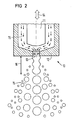
- 11 denotes the nozzle needle, which also acts as a valve needle. It is located in the nozzle part 12 which has the bore shown as the nozzle opening 13. If the injection nozzle is closed, the front end of the nozzle needle 11 closes the nozzle opening 13. 14 indicates the controllable mobility of the nozzle needle 11.
- fuel indicated at 15 flows along the nozzle needle 11 and within the nozzle part 12 to the nozzle opening 13 in order to form an injection jet with the conical shape having the characteristic 15 shown.
- This jet shape 15 results from the fact that the nozzle needle 11 in the open position is superimposed on the additional alternating stroke movement indicated by 14.
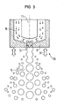
- FIG. 3 reference can largely be made to the details described for FIG. 2. Reference symbols already described for FIG. 2 have the same or at least meaningful meaning in FIG. 3.
- alternating stroke movement is provided for the nozzle part 12 with the nozzle opening 13.
- there is a beam shape which essentially corresponds to that of the embodiment according to FIG. 2.
- FIGS. 4 and 5 show an additional device attached to the nozzle part 12 in the region of the nozzle opening 13.
- FIG. 5 shows an end view belonging to FIG. 4, ie a view against the sprayed jet.
- This additional device 51 of the actual injection nozzle of FIGS. 4 and 5 consist of, for example, four rod-shaped extensions 151, each of which are to be excited to perform lifting movements. These lifting movements are indicated by the individual arrows 54.
- These stroke movements 54 are bending movements of the parts 151.
- These parts 151 form longitudinal guides for the fuel jet 45 emerging from the nozzle opening 13.
- the alternating stroke movements 54 which are transverse to its jet direction, lead to a jet shape as shown at 55.
- the drive element 6 according to FIG. 6 consists of a stack of piezoelectrically excitable disks 61. These disks are provided with flat electrodes, not shown. Such stacks are known in principle and are also supplied with controlled electrical voltage in the present case. In particular, AC voltage is supplied, preferably with such a frequency that leads to resonant oscillatory movements of the lifting movement 114 of the stack or of the drive 6.
- FIG. 7 shows a magnetostrictive embodiment 7 of a drive.
- 71 denotes a rod which can be excited to magnetostriction movements and which is located inside a magnetic field coil 72.
- This magnetic field coil 72 is supplied with electrical voltage, preferably again at a frequency which leads to resonance with a natural oscillation of the rod 71, which leads to a correspondingly large stroke amplitude of the stroke movement 114.
- FIG. 8 shows a drive 8 with plunger coil 81 and pot magnet 82, as is known in principle from loudspeakers. With a corresponding electrical alternating excitation, such a device leads to mechanical stroke movements 114. Resonance excitation can also be effected here.
- FIG. 9 shows an example of an injection nozzle according to the invention.
- the details given for the figures described above have the same meaning in FIG. 9.
- the actuator 91 denotes an actuator, for example a stack consisting of piezoelectric plates. By applying electrical voltage between the connections 92 and 93, this actuator changes its length and thus drives the plunger 94 and the nozzle needle 11 connected to the plunger 94.
- the actuator 91 is used to open and close the valve by moving the valve needle 11.
- the inflow opening of the injection nozzle for the fuel is designated by 95.
- the drive device for the alternating lifting movement to be carried out according to the invention is designated by 96.
- this drive device comprises a plurality of stacks 97 with the electrical connecting lines 98 and 99. Between the connections 98 and 99, the AC drive voltage for this lifting movement is to be applied.
- the outer housing 12 of the injection nozzle is (sealed) divided, this nozzle part 12 guides through the work of the drive 96 perform the alternating stroke movements according to the invention, specifically compared to the nozzle needle which is stationary in this example in the open state. This corresponds to the embodiment variant of the invention already described above in connection with FIG. 3.
Abstract
Einspritzdüse mit einer Düsenbohrung (13) und einer Düsennadel (11), und mit einem Antrieb (91) mit elektrischer Eingangsgröße sowie mit eine Antriebseinrichtung (96) für eine dem geöffneten Zustand der Einspritzdüse überlagerte wechselende Hubbewegung des Düsenteils (12), wobei die Antriebseinrichtung (96) mit elektrischer Eingangsfröße anregbar ist und konstruktiv so ausgebildet ist, daß mindestens eine solche kleine Periodendauer für die Wechsel der Hubbewegung verfügbar ist, die mehrfach kleiner als die vorgegebene Mindestöffnungszeit der Einspritzdüse ist.Injection nozzle with a nozzle bore (13) and a nozzle needle (11), and with a drive (91) with an electrical input variable and with a drive device (96) for an alternating lifting movement of the nozzle part (12) superimposed on the open state of the injection nozzle, the drive device (96) can be excited with an electrical input variable and is designed in such a way that at least one such small period is available for changing the stroke movement, which is several times smaller than the predetermined minimum opening time of the injection nozzle.
Description
Die vorliegende Erfindung bezieht sich auf eine Kraftstoff-Einspritzdüse wie sie im Oberbegriff des Patentanspruches 1 angegeben ist.The present invention relates to a fuel injector as specified in the preamble of claim 1.
Schon seit langem ist es zunächst für Dieselmotore und dann für Ottomotore bekannt, den für den Betrieb notwendigen Kraftstoff an einer jeweils vorgegebenen Stelle der Verbrennungskraft maschine unter Druck einzuspritzen. Es kann dies Kraftstoffeinspritzung in einen Raum hinter dem Einlaßventil sein. Für Ottomotore ist auch Einspritzung auf das Einlaßventil oder in das Saugrohr vor dem Einlaßventil üblich.For a long time it has been known first for diesel engines and then for gasoline engines to inject the fuel required for operation under pressure at a predetermined point in the internal combustion engine. This can be fuel injection into a space behind the intake valve. Injection to the intake valve or to the intake manifold before the intake valve is also common for gasoline engines.
Es gibt Bestrebungen, eine Einspritzdüse so auszugestalten und zu betreiben, daß sie ein feineres Aerosol erzeugt, als dies mit einer Einspritzdüse ohnehin üblich und/oder möglich ist. Bei solchen Einspritzdüsen ist zusätzlich Ultraschall-Vibration vorgesehen, wie dies für Ultraschall-Flüssigkeitszer stäuber schon seit langen bekannt war. Die anzuwendende Ultraschallfrequenz liegt für Flüssigkeitszerstäubung im Bereich von oberhalb 100 KHz, und zwar abhängig von der Ausgestaltung eines jeweils vorgesehenen ultraschallfrequent-schwingenden Teils der Düse. Die Einspritzdüse erzeugt dabei für sich genommen einen der konstruktiven Ausgestaltungen entsprechenden Kraftstoffstrahl, der von dem ultraschallfrequent-schwingenden Teil ab den Charakter eines strömenden Tröpfchennebels, bestehend aus feinen Aeorosoltröpfchen, hat.There are efforts to design and operate an injector in such a way that it produces a finer aerosol than is customary and / or possible with an injector anyway. In such injection nozzles, ultrasonic vibration is additionally provided, as has been known for a long time for ultrasonic liquid atomizers. The ultrasound frequency to be used for liquid atomization is in the range above 100 KHz, depending on the configuration of a part of the nozzle which oscillates at the ultrasonic frequency. The injection nozzle generates a fuel jet that corresponds to the design and has the character of a flowing droplet mist consisting of fine aerosol droplets from the part that vibrates at the ultrasonic frequency.
Alle bekannten Kraftstoffeinspritzdüsen haben eine durch ihre Konstruktion vorgegebene charakteristische Form des Kraftstoffstrahls. Die Form des Kraftstoffstrahls ist bekanntlich für die Luft-Kraftstoff-Gemischbildung wichtig, und zwar nicht nur im Hinblick auf minimalen spezifischen Kraftstoffverbrauch, sondern auch im Hinblick auf Umweltbelastung durch unerwünscht auftretende Abgasanteile, und wichtig für die Laufruhe des Motors. Zum Beispiel wird unterschieden zwischen von einer Kraftstoff-Einspritzdüse, die einen Fadenstrahl erzeugt und einer Düse, die einen Kegelstrahl liefert. Beide Strahlformen haben für sich charakteristisch im übrigen u.a. auch unterschiedliche Größenverteilungen der Tröpfchen des aus der Düse gespritzten Kraftstoffes.All known fuel injection nozzles have a characteristic shape of the fuel jet which is predetermined by their construction. The shape of the fuel jet is known to be important for the air-fuel mixture formation, and not only in the With regard to minimal specific fuel consumption, but also with regard to environmental pollution due to undesirable emissions, and important for the smooth running of the engine. For example, a distinction is made between a fuel injection nozzle that generates a thread jet and a nozzle that delivers a cone jet. Both jet shapes are characteristic of one another, moreover, different size distributions of the droplets of the fuel sprayed out of the nozzle.
Von Parametern einer jeweiligen Verbrennungskraftmaschine und deren Konstruktionsmerkmalen sowie dem jeweiligen Lastzustand abhängig sind jeweils verschiedene Strahlformen optimal.Depending on the parameters of a particular internal combustion engine and their design features as well as the respective load condition, different jet shapes are optimal.
Aufgabe der vorliegenden Erfindung ist es, Maßnahmen anzugeben, mit denen außerdem auch für unterschiedliche Betriebszustände der Verbrennungskraftmaschine wenigstens weitgehend jeweils optimale Gemischbildung mit der ausgewählten Einspritzdüse zu erreichen ist.The object of the present invention is to provide measures with which, in addition, at least largely optimal mixture formation can also be achieved with the selected injection nozzle for different operating states of the internal combustion engine.
Diese Aufgabe wird mit den Maßnahmen des Patentanspruches 1 gelöst und weitere Ausgestaltungen und Weiterbildungen der Erfindung gehen aus den Unteransprüchen hervor.This object is achieved with the measures of claim 1 and further refinements and developments of the invention emerge from the subclaims.
Der vorliegenden Erfindung liegt der Gedanke zugrunde, an einer bzw. für eine Kraftstoff-Einspritzdüse technische Mittel vorzusehen, mit denen im Betrieb die charakteristische Form des Kraftstoffstrahls dieser einen Düse elektrisch steuerbar verändert werden kann. Es wird erfindungsgemäß mit diesen Mitteln die Form des Strahls der Düse so gesteuert, daß verschiedene Öffnungswinkel des Einspritzstrahls, vom (schlanken) Fadenstrahl bis zu einem Kegelstrahl mit z.B. 70o Öffnungswinkel oder sogar noch größer erreichbar sind.The present invention is based on the idea of providing technical means on or for a fuel injection nozzle, with which the characteristic shape of the fuel jet of this one nozzle can be changed in an electrically controllable manner during operation. According to the invention, the shape of the jet of the nozzle is controlled with these means in such a way that different opening angles of the injection jet, from the (slender) thread jet to a cone jet with, for example, 70 ° opening angle or even larger can be reached.
Mit einer erfindungsgemäßen Einspritzdüse läßt sich im Betrieb die Strahlform steuerbar verändern und optimal anpassen. Außerdem wird dabei eine steuerbare Veränderung der Verteilung der Tröpfchengröße durchgeführt. Die Erfindung bezieht sich insbesondere auf Niederdruck-Einspritzung mit etwa 1 bis 10 bar.With an injection nozzle according to the invention, the spray shape can be controlled and optimally adjusted during operation. In addition, a controllable change in the distribution of the droplet size is carried out. The invention relates in particular to low-pressure injection at approximately 1 to 10 bar.
In der überwiegenden Anzahl der Fälle sind Kraftstoff-Einspritzdüsen gleichzeitig auch Einspritzventile. Der Ventilantrieb kann dabei auf der Wirkung des vom einzuspritzenden Kraftstoff ausgeübten Flüssigkeitsdruckes beruhen. Zunehmend werden aber Einspritzdüsen mit elektromechanischen Einrichtungen zum Öffnen und Schließen ihres Ventilanteils versehen. Vorwiegend sind hierzu elektromagnetische Ausführungen vorgesehen worden. Es gibt bereits auch Kraftstoff-Einspritzdüsen mit Ventileinrichtung mit piezoelektrischem Antrieb.In the vast majority of cases, fuel injectors are also injectors. The valve drive can be based on the effect of the liquid pressure exerted by the fuel to be injected. However, injection nozzles are increasingly being provided with electromechanical devices for opening and closing their valve portion. Electromagnetic versions have mainly been provided for this purpose. There are also fuel injectors with a valve device with a piezoelectric drive.
Mit der vorliegenden Erfindung ist erreicht, unter Einhaltung von als besonders sinnvoll erkannten Randbedingungen eine Lösung zu haben, die es ermöglicht, solche variierten Strahlformen mit einer einzigen Einspritzdüse einstellen zu können, die den verschiedenartigen Betriebsbedingungen eines Verbrennungs-Kolbenmotors weitestgehend optimal angepaßt sind. Diese verschiedenen Betriebsbedingungen sind insbesondere zum einen die Kaltstart-Phase und andererseits der Dauerbetrieb des Motors mit stationär durchgewärmtem Motor. Es wäre denkbar, insbesondere für die beiden vorangehend genannten Betriebszustände zwei verschiedene Einspritzdüsen vorzusehen, die jede auf die ihr zugeordnete Betriebsphase optimiert sein könnte. Es soll aber nur eine Einspritzdüse vorgesehen sein. Bezüglich der Kaltstart-Phase ist vor allem die Randbedingung zu erfüllen, daß der jeweils im Ansaugtakt des Motors eingespritzte Kraftstoff als kegelförmiger Strahl so stark zerstäubt in den Zylinder gelangt, daß auch tatsächlich die bestimmungsgemäße Kraftstoffvermischung mit Luft und damit Kraftstoffverbrennung erfolgt.With the present invention it is achieved, while observing boundary conditions recognized as particularly useful, to have a solution which makes it possible to set such varied jet shapes with a single injection nozzle which are largely optimally adapted to the different operating conditions of a combustion piston engine. These various operating conditions are in particular the cold start phase on the one hand and the continuous operation of the engine with the engine warmed up in a stationary manner on the other hand. It would be conceivable to provide two different injection nozzles in particular for the two operating states mentioned above, each of which could be optimized for the operating phase assigned to it. However, only one injector should be provided. With regard to the cold start phase, the boundary condition must be met in particular that the fuel injected in the intake stroke of the engine as a cone-shaped jet reaches the cylinder so strongly that the intended fuel mixing with air and thus fuel combustion actually takes place.
In der Dauerbetriebsphase, d.h. bei Betriebstemperatur aller Motorteile, ist insbesondere ein heißes Einlaßventil vorhanden, das sich hervorragend zur Kraftstoff-Feinverteilung bzw. -verdampfung eignet. Es ist auch dementsprechend durchaus üblich, den einzuspritzenden Kraftstoff mit einem weitgehend fadenförmigen oder nur gering aufgefächerten Einspritzstrahl auf den heißen Ventilteller zu richten und dort auftreffen zu lassen.In the continuous operating phase, ie at the operating temperature of all engine parts, there is in particular a hot inlet valve which is excellent for fine fuel distribution or evaporation is suitable. Accordingly, it is also quite common to direct the fuel to be injected onto the hot valve plate with a largely filament-shaped or only slightly fanned-out injection jet and to have it hit there.
Im Zusammenhang mit der Erfindung ist festgestellt worden, daß es fallweise nicht unbedingt vorteilhaft ist, in der Dauerbetriebsphase eine schon direkt von der Einspritzdüse ausgehende größere insbesondere durch Ultraschall erzeugte Zerstäubung des einzuspritzenden Kraftstoffes vorzusehen. Es ist nämlich beobachtet worden, daß trotz hoher Betriebswärme des Motorblocks durchaus nachteilige Zustände bei schon von der Düse weg feinverteiltem bzw. zerstäubtem Kraftstoff auftreten. Zum einen können im doch nur begrenzt stark erwärmten Ansaugrohr noch Abscheidungen von Kraftstofftröpfchen erfolgen, die dann erst zeitverzögert zum falschen Zeitpunkt durch Wiederabdampfen in den Zylinder gelangen. Luftsäulenschwingun gen im Ansaugrohr können ebenfalls zu Zuständen führen, daß schon vom Ort der Düse weg zerstäubter Kraftstoff nicht zum gewollten Zeitpunkt in den jeweiligen Zylinder gelangt. Damit sind in jedem Falle unerwünschte Verschiebungen hinsichtlich des Kraftstoff-Luft-Verhältnisses verbunden, das beabsichtigterweise möglichst genau zugemessenen sein soll.In connection with the invention it has been found that in some cases it is not absolutely advantageous to provide a larger atomization of the fuel to be injected, which is generated directly from the injection nozzle, in the continuous operating phase. It has been observed that, despite the high operating heat of the engine block, disadvantageous conditions occur with fuel that has already been finely divided or atomized away from the nozzle. On the one hand, fuel droplets can still be deposited in the intake pipe, which is only heated to a limited extent, and then only delayed at the wrong time by re-evaporation. Air column vibrations in the intake manifold can also lead to conditions such that fuel atomized away from the location of the nozzle does not get into the respective cylinder at the desired time. In any case, this is associated with undesirable shifts in the fuel-air ratio, which is intended to be measured as precisely as possible.
Erfindungsgemäß ist die eine einzige Kraftstoff-Einspritzdüse pro Zylinder so ausgebildet, daß sie mehrere voneinander verschiedene, steuerbar wählbare Formen der "Strahlausbildung" bewirken kann. Aufgrund dieser Steuerbarkeit läßt sich mit einer erfindungsgemäßen Kraftstoffeinspritzdüse, nämlich für den Dauerbetrieb, ein "Fadenstrahl" erzeugen, dessen Auftreffquerschnitt auf dem Ventil auf einen vorgebbaren Anteil der Ventilteller-Oberfläche begrenzt ist. Damit ist erreicht, daß der Kraftstoff möglichst "verlustlos" auf das Ventil und weiter sofort und ohne Umweg in den Zylinder gelangt. Das zugemessene optimale Kraftstoff-Luftverhältnis kann damit mit Sicherheit eingehalten werden. Aufgrund der Verdampfung des Kraftstoffs auf dem heißen Ventilteller ist sichergestellt, daß zur Verbrennung im Zylinder optimal fein verteiltes Kraftstoff-Luftgemisch zur Verfügung steht.According to the invention, the one fuel injection nozzle per cylinder is designed in such a way that it can bring about several mutually different, controllably selectable forms of "jet formation". On account of this controllability, a "thread jet" can be generated with a fuel injection nozzle according to the invention, namely for continuous operation, the cross section of the impact on the valve being limited to a predeterminable proportion of the valve disk surface. This ensures that the fuel reaches the valve as "lossless" as possible and then immediately and without detour into the cylinder. The measured optimal air-fuel ratio can thus be maintained with certainty. The evaporation of the fuel on the hot valve plate ensures that a finely divided fuel-air mixture is available for combustion in the cylinder.
In der Kaltstartphase wird die erfindungsgemäße Einspritzdüse so gesteuert, daß eine gute Kraftstoff-Feinverteilung auftritt. Mit der erfindungsgemäßen Einspritzdüse wird für diese Betriebsphase des Motors ein Einspritz-"Strahl" erzeugt, der eine gewisse Aufspreizung nach Art eines Kegelstrahls besitzt. Ein solcher Kegelstrahl hat die Eigenschaft, daß, und zwar erst in einer gewissen Entfernung von seiner Düsenöffnung, die Flüssigkeit erst im Strahl zerfällt und daß erst dann, aber für den Verbrennungsvorgang genügend zeitig, ein wesentlicher Anteil der Einspritzmenge in feiner Tröpfchenverteilung vorliegt. Der voranstehend erwähnte dabei auftretende Abstand ist dabei wichtig, denn damit kann erreicht werden, daß erst dicht vor oder gar erst am Einlaßventil diese Kraftstoff-Feinverteilung im Kegelstrahl vorliegt und ein Ausfallen von Tröpfchen z.B. an der Wandung des Ansaugrohres (also im Bereich zwischen der Düsenöffnung und dem Einlaßventil) ausgeschlossen ist. Dieser Vorteil tritt besonders bei solchen bekannten Einspritzdüsen auf, die eine integrierte Ultraschall-Flüssigkeitszerstäubung haben. Es ist ja zu berücksichtigen, daß die Kraftstoffeinspritzdüse nicht beliebig nahe dem Einlaßventil angeordnet werden kann.In the cold start phase, the injection nozzle according to the invention is controlled so that a good fuel fine distribution occurs. With the injection nozzle according to the invention, an injection “jet” is generated for this operating phase of the engine, which has a certain spreading in the manner of a cone jet. Such a cone jet has the property that, and only at a certain distance from its nozzle opening, the liquid only disintegrates in the jet and that only then, but sufficiently early for the combustion process, is there a substantial proportion of the injection quantity in fine droplet distribution. The above-mentioned distance is important here, because it can be achieved that this fuel fine distribution in the cone jet is present just before or even at the inlet valve and that droplets fail, e.g. on the wall of the intake pipe (i.e. in the area between the nozzle opening and the inlet valve) is excluded. This advantage occurs particularly in such known injection nozzles that have an integrated ultrasonic liquid atomization. It must be taken into account that the fuel injector cannot be arranged anywhere near the inlet valve.
Mit der Erfindung ist, und zwar schon mit nur bescheiden höherem Aufwand, auch für die Kaltstartphase ein wesentlich vorteilhafteres Ergebnis zu erreichen als es eine an sich bekannte Kraftstoff-Einspritzdüse, die für Ultraschall-Kraftstoffzerstäubung ausgebildet ist, verspricht. Es ist nämlich festgestellt worden, daß bei intermittierender, zylinderselektiver Einspritzung für wirklich quantitative Kraftstoffzerstäubung durch Ultraschall auch derart hohe Ultraschallenergie erforderlich wäre, wie sie in der Praxis zumindest mit Rücksicht auf die konstruktive Größe einer Einspritzdüse überhaupt nicht bereitgestellt werden kann.With the invention, even with only a modestly higher effort, it is also possible to achieve a much more advantageous result for the cold start phase than a fuel injection nozzle known per se, which is designed for ultrasonic fuel atomization, promises. It has been found that with intermittent, cylinder-selective injection for truly quantitative fuel atomization by ultrasound, such high ultrasound energy would be required as cannot be provided in practice at least with regard to the structural size of an injection nozzle.
Eine erfindungsgemäße Einspritzdüse ist so ausgelegt, daß sie einen schnell ansprechenden und schnell arbeitenden Antrieb für das Öffnen und Schließen der Düsenöffnung besitzt. Es kann im Einzelfall von Vorteil sein, und zwar insbesondere für optimales Erfüllen der Bedingungen im Leerlaufbetrieb, wenn die erfindungsgemäße Einspritzdüse eine solche mit proportionalem Antrieb bzw. proportionaler Einstellbarkeit der Düsenöffnung ist. Damit lassen sich nämlich leicht solche Zwischenwerte des Öffnungsgrades der Einspritzdüse definiert einstellen, mit denen eine genaue Zumessung der gerade im Leerlaufbetrieb in Betracht kommenden sehr geringen Einspritzmengen pro Einspritzvorgang einhalten.An injection nozzle according to the invention is designed so that it has a fast responding and fast working drive for opening and closing the nozzle opening. It can be advantageous in individual cases, in particular for optimally fulfilling the conditions in idle mode, if the injection nozzle according to the invention is one with proportional drive or proportional adjustability of the nozzle opening. It is thus easy to set such intermediate values of the degree of opening of the injection nozzle, with which an exact metering of the very small injection quantities that come into consideration, especially in idle mode, can be maintained per injection process.
Im praktischen Einsatz liegt die Betriebs-Folgefrequenz, z.B. für einen Vier-Zylinder- bzw. Sechs-Zylinder-Motor und damit die Folgefrequenz für das Öffnen (t₁) und Schließen (t₂) des Ventilanteils der Einspritzdüse bei etwa 5 Hz bis 50 Hz. Entsprechend steile Anstiegs- und Abfallflanken des Öffnens und Schließens einer erfindungsgemäßen Einspritzdüse liegen bei einer Frequenz von erheblich oberhalb 1 kHz (mit entsprechender Periodendauer T) als obere Grenze des Fourierspektrums des Impulses des Öffnens und Schließens.The operational repetition frequency is in practical use, e.g. for a four-cylinder or six-cylinder engine and thus the repetition frequency for opening (t₁) and closing (t₂) the valve portion of the injector at about 5 Hz to 50 Hz. Correspondingly steep rising and falling edges of opening and closing of an injection nozzle according to the invention are at a frequency of considerably above 1 kHz (with a corresponding period T) as the upper limit of the Fourier spectrum of the opening and closing impulse.
Die Anforderungen an eine erfindungsgemäße Einspritzdüse seien anhand der nachfolgenden, beispielhaften Betriebswerte für einen Mittelklasse-Personenwagen angegeben:The requirements for an injection nozzle according to the invention are given on the basis of the following exemplary operating values for a medium-sized passenger car:
Der Treibstoffdurchsatz bei Daueröffnung der Einspritzdüse (in der Ansaugphase) beträgt ca. 6 g/s pro Zylinder. Dies entspricht nahezu Voll-Lastbetrieb.The fuel throughput when the injector is continuously open (in the intake phase) is approx. 6 g / s per cylinder. This corresponds to almost full load operation.
Der Leerlaufdurchsatz eines solchen Motors beträgt etwa 0,4 mg/s pro Zylinder. Ersichtlich ergibt sich daraus ein zu bewältigender Dynamikbereich von vier Größenordnungen.The idle flow rate of such an engine is about 0.4 mg / s per cylinder. This clearly results in a dynamic range of four orders of magnitude to be managed.
Besondere Ausführungsformen einer erfindungsgemäßen Einspritzdüse sind dadurch gekennzeichnet, daß die an sich dem Öffnen und Schließen der (auch als Ventil ausgebildeten) Einspritz düse dienende Ventilnadel und/oder der Öffnungsquerschnitt der Düse in Hubbewegungen zu versetzen sind. In Abhängigkeit von der elektrisch einstellbaren Hub-Periode kann der Strahlquerschnitt, d.h. die Strahlform z.B. vom Fadenstrahl bis zum Kegelstrahl mit verschiedenen Öffnungswinkeln variiert werden. Zur Verdeutlichung dient die beigefügte Figur 1, die ein Zeit/Anregungs-bzw. Öffnungsdiagramm einer erfindungsgemäßen Einspritzdüse zeigt. Die erfindungsgemäße Einspritzdüse ist aufgrund des oben erwähnten schnellen Ansprechens ihrer Teile, insbesondere bei proportionalem Antrieb, in der Lage mit ihren Hubbewegungen periodisch den mechanischen Bewegungen der elektrischen Anregung zu folgen. Die in der Figur 1 gezeigte Modulation bezieht sich auf eine Ausführungsform nach Figur 2 bzw. 3. Die Anregungsfrequenzen für diese Hubbewegung liegen optimal im Bereich von 5 KHz bis 20 KHz, also weit unterhalb von Ultraschall-Zerstäuberfrequenzen. Diese Bemessung gilt sowohl für Einspritzdüsen bzw. -ventile in Niederdrucksystemen (ca. 3bar) als auch für solche mit üblichem Durchmesser (0,3 bis 1 mm) der Düse.
- Figur 2 zeigt einen prinzipiellen Aufbau einer
erfindungsgemäßen Einspritzdüse 10 mit überlagerter, rasch wechselnder Hubbewegung der Düsennadel. - Figur 3 zeigt eine entsprechende Ausführungsform mit Hubbewegung des (Ventil-)Sitzes der
Einspritzdüse 20. - Die Figuren 4 und 5 zeigen in Seiten- und in Frontansicht eine
Ausführungsform 40 mit einer Vorrichtung zum Modulieren der wirksamen Einspritzöffnung. Figur 6 zeigt eine piezokeramische Antriebseinrichtung.- Figur 7 zeigt eine magnetostriktive Antriebseinrichtung und
Figur 8 eine elektrodynamische Antriebseinrichtung für eine erfindungsgemäße Einspritzdüse.- Figur 9 zeigt eine erfindungsgemäße Einspritzdüse in kompletter Ausführung.
- FIG. 2 shows a basic structure of an
injection nozzle 10 according to the invention with a superimposed, rapidly changing stroke movement of the nozzle needle. - FIG. 3 shows a corresponding embodiment with a lifting movement of the (valve) seat of the
injection nozzle 20. - Figures 4 and 5 show in side and front view an
embodiment 40 with a device for modulating the effective injection opening. - Figure 6 shows a piezoceramic drive device.
- FIG. 7 shows a magnetostrictive drive device and
- 8 shows an electrodynamic drive device for an injection nozzle according to the invention.
- FIG. 9 shows a complete configuration of an injection nozzle according to the invention.
In Figur 2 ist mit 11 die Düsennadel bezeichnet, die auch als Ventilnadel wirkt. Sie befindet sich in demjenigen Düsenteil 12, das als Düsenöffnung 13 die dargestellte Bohrung besitzt. Ist die Einspritzdüse geschlossen, so verschließt das vordere Ende der Düsennadel 11 die Düsenöffnung 13. Mit 14 ist auf die steuerbare Beweglichkeit der Düsennadel 11 hingewiesen. Im geöffneten Zustand der Einspritzdüse strömt mit 15 angedeuteter Kraftstoff entlang der Düsennadel 11 und innerhalb des Düsenteils 12 zur Düsenöffnung 13, um einen die dargestellte Charakteristik 15 aufweisenden Einspritzstrahl mit Kegelform zu bilden. Diese Strahlform 15 ergibt sich dadurch, daß der in Öffnungsposition befindlichen Düsennadel 11 die mit 14 angedeutete zusätzliche wechselnde Hubbewegung überlagert ist. Mit 16 ist auf die bereits oben angesprochene (hier sogar noch verkürzt dargestellte) Wegstrecke hingewiesen, innerhalb der, ausgehend von der Düsenöffnung 13, der ausgespritzte Kegelstrahl noch keine wesentliche Zerteilung in Tröpfchen aufweist. Dies zeigt im übrigen deutlich den Unterschied zu Ultraschall-Kraftstoffzerstäubung, bei der die Tröpfchen am schwingenden Teil entstehen und von diesem ausgehen.In Figure 2, 11 denotes the nozzle needle, which also acts as a valve needle. It is located in the
Bezüglich der Figur 3 kann weitgehend auf zur Figur 2 beschriebene Einzelheiten verwiesen werden. Zur Figur 2 bereits beschriebene Bezugszeichen haben in Figur 3 gleiche oder wenigstens sinngemäße Bedeutung. Für die Ausführungsform nach Figur 3 ist wechselnde Hubbewegung für das Düsenteil 12 mit der Düsenöffnung 13 vorgesehen. Für eine Ausführungsform nach Figur 3 ergibt sich eine Strahlform, die im wesentlichen derjenigen der Ausführungsform nach Figur 2 entspricht.With regard to FIG. 3, reference can largely be made to the details described for FIG. 2. Reference symbols already described for FIG. 2 have the same or at least meaningful meaning in FIG. 3. For the embodiment according to FIG. 3, alternating stroke movement is provided for the
Die Figuren 4 und 5 zeigen eine im Bereich der Düsenöffnung 13 am Düsenteil 12 angebrachte Zusatzeinrichtung. Die Figur 5 zeigt eine zur Figur 4 gehörende stirnseitige Ansicht, d.h. eine Ansicht entgegen dem ausgespritzten Strahl. Diese zusätzliche Einrichtung 51 der eigentlichen Einspritzdüse der Figuren 4 und 5 bestehen aus z.B. vier stabförmigen Fortsetzungen 151, die jede für sich zu Hubbewegungen anzuregen sind. Diese Hubbewegungen sind mit den einzelnen Pfeilen 54 angedeutet. Diese Hubbewegungen 54 sind Biegebewegungen der Teile 151. Diese Teile 151 bilden Längsführungen für den aus der Düsenöffnung 13 austretenden Kraftstoffstrahl 45. Die zu dessen Strahlrichtung transversalen wechselnden Hubbewegungen 54 führen zur einer wie mit 55 dargestellten Strahlform.FIGS. 4 and 5 show an additional device attached to the
Das Antriebselement 6 nach Figur 6 besteht aus einem Stapel piezoelektrisch anregbarer Scheiben 61. Diese Scheiben sind mit nicht dargestellten flächigen Elektroden versehen. Solche Stapel sind an sich prinzipiell bekannt und sie werden auch im vorliegenden Falle mit gesteuerter elektrischer Spannung gespeist. Insbesondere erfolgt Speisung mit Wechselspannung, und zwar vorzugsweise mit einer solchen mit einer derartigen Frequenz, die zu Resonanzschwingungsbewegungen der Hubbewegung 114 des Stapels bzw. des Antriebes 6 führt.The
Die Figur 7 zeigt eine magnetostriktive Ausführungsform 7 eines Antriebes. Mit 71 ist ein zu Magnetostriktions-Bewegungen anregbarer Stab bezeichnet, der sich im Inneren einer Magnetfeldspule 72 befindet. Diese Magnetfeldspule 72 wird mit elektrischer Spannung gespeist, und zwar vorzugsweise wiederum mit einer Frequenz, die zu Resonanz mit einer Eigenschwingung des Stabes 71 führt, die zu entsprechend großer Hubamplitude der Hubbewegung 114 führt.FIG. 7 shows a magnetostrictive embodiment 7 of a drive. 71 denotes a rod which can be excited to magnetostriction movements and which is located inside a
In Figur 8 ist ein Antrieb 8 mit Tauchspule 81 und Topfmagnet 82 dargestellt, wie er prinzipiell von Lautsprechern her bekannt ist. Eine solche Einrichtung führt bei entsprechender elektrischer Wechselanregung zu mechanischen Hubbewegungen 114. Es kann auch hier Resonanzanregung bewirkt werden.FIG. 8 shows a
Figur 9 zeigt ein Beispiel einer erfindungsgemäßen Einspritzdüse. Zu den vorangehend beschriebenen Figuren angegebene Einzelheiten haben in Figur 9 dieselbe Bedeutung.FIG. 9 shows an example of an injection nozzle according to the invention. The details given for the figures described above have the same meaning in FIG. 9.
Mit 91 ist ein Aktuator, beispielsweise ein Stapel aus piezoelektrischen Platten bestehend, bezeichnet. Durch Anlegen elektrischer Spannung zwischen den Anschlüssen 92 und 93 ändert dieser Aktuator seine Länge und treibt damit den Stößel 94 und die mit dem Stößel 94 verbundene Düsennadel 11 an. Der Aktuator 91 dient zum Öffnen und Schließen des Ventils durch Bewegung der Ventilnadel 11. Mit 95 ist die Zuflußöffnung der Einspritzdüse für den Kraftstoff bezeichnet.91 denotes an actuator, for example a stack consisting of piezoelectric plates. By applying electrical voltage between the
Mit 96 ist zusammengenommen die Antriebseinrichtung für die erfindungsgemäß auszuführende Wechsel-Hubbewegung bezeichnet. Diese Antriebseinrichtung umfaßt bei diesem Beispiel mehrere Stapel 97 mit den elektrischen Anschlußleitungen 98 und 99. Zwischen die Anschlüsse 98 und 99 ist die Antriebs-Wechselspannung für diese Hubbewegung anzulegen. Bei (wechselnder) Längenänderung der Plattenstapel 97 infolge des piezoelektrischen Effekts ergibt sich entsprechende Längenänderung des Gehäuses 100 der Antriebseinrichtung 96. Da, wie aus der Figur ersichtlich, das äußere Gehäuse 12 der Einspritzdüse (abgedichtet) geteilt ist, führt dieses Düsenteil 12 durch das Arbeiten des Antriebs 96 die erfindungsgemäßen Wechsel-Hubbewegungen aus, und zwar gegenüber der bei diesem Beispiel in geöffentem Zustand stillstehenden Düsennadel. Dies entspricht der schon oben im Zusammenhang mit der Figur 3 beschriebenen Ausführungsvariante der Erfindung.The drive device for the alternating lifting movement to be carried out according to the invention is designated by 96. In this example, this drive device comprises a plurality of
Claims (13)
gekennzeichnet dadurch,
daß die Periodendauer (T) einer Anregungsfrequenz zwischen 5 KHz und 20 KHz entsprechend bemessen ist.2. Injection nozzle according to claim 1,
characterized by
that the period (T) of an excitation frequency between 5 KHz and 20 KHz is dimensioned accordingly.
gekennzeichnet dadurch,
daß zusätzlich zur anzulegenden elektrischen Betätigungsspannung (Uein/aus) zum Öffnen der Düse eine weitere Wechselspannung (U ) zur Anregung der Wechselhubbewegung (14, 24) vorgesehen ist.3. Injection nozzle according to claim 1 or 2,
characterized by
that in addition to the electrical actuating voltage (U on / off ) to be applied to open the nozzle, a further alternating voltage (U) is provided to excite the alternating stroke movement (14, 24).
gekennzeichnet dadurch,
daß die Mittel zur Ausführung der Wechsel-Hubbewegung (114, 14, 24, 54) ein Resonanzsystem bilden.4. Injection nozzle according to claim 1, 2 or 3,
characterized by
that the means for executing the alternating lifting movement (114, 14, 24, 54) form a resonance system.
gekennzeichnet dadurch,
daß die Mittel zur Anregung der Wechsel-Hubbewegung (114, 14, 24, 54) derart ausgebildet sind, daß die Düsennadel (11) diese Wechsel-Hubbewegungen ausführt. (Fig. 2)5. Injection nozzle according to one of claims 1 to 4,
characterized by
that the means for exciting the alternating stroke movement (114, 14, 24, 54) are designed in such a way that the nozzle needle (11) executes these alternating stroke movements. (Fig. 2)
gekennzeichnet dadurch,
daß die Mittel zur Anregung der Wechsel-Hubbewegung (114, 14, 24, 54) derart ausgebildet sind, daß ein Anteil der Düsenbohrung (12, 13) diese Wechsel-Hubbewegung ausführt. (Fig. 3)6. Injection nozzle according to one of claims 1 to 4,
characterized by
that the means for exciting the alternating stroke movement (114, 14, 24, 54) are designed such that a portion of the nozzle bore (12, 13) executes this alternating stroke movement. (Fig. 3)
gekennzeichnet dadurch,
daß longitudinale Wechsel-Hubbewegung (14,24) vorgesehen ist.7. Injection nozzle according to one of claims 1 to 6,
characterized by
that longitudinal alternating stroke movement (14, 24) is provided.
gekennzeichnet dadurch,
daß transversale Wechsel-Hubbewegung (54) vorgesehen ist.8. Injection nozzle according to one of claims 1 to 6,
characterized by
that transverse alternating stroke movement (54) is provided.
gekennzeichnet dadurch,
daß diese Mittel eine piezoelektrische Anregungseinrichtung (6) umfassen.9. Injection nozzle according to one of claims 1 to 8,
characterized by
that these means comprise a piezoelectric excitation device (6).
gekennzeichnet dadurch,
daß diese Mittel eine elektrodynamische Einrichtung (8) mit homogenem Magnetfeld umfassen.10. Injection nozzle according to one of claims 1 to 8,
characterized by
that these means comprise an electrodynamic device (8) with a homogeneous magnetic field.
gekennzeichnet dadurch,
daß diese Mittel eine magnetostriktive Einrichtung (7) umfassen.11. Injection nozzle according to one of claims 1 to 8,
characterized by
that these means comprise a magnetostrictive device (7).
gekennzeichnet dadurch,
daß diese Mittel eine elektromagnetische Einrichtung (7, 8) umfassen.12. Injection nozzle according to one of claims 1 to 8,
characterized by
that these means comprise an electromagnetic device (7, 8).
gekennzeichnet durch,
eine Anregung eines Anteils (11,12,51) der Düse (10,20,40) zu Hubbewegungen mit einer Wechselfrequenz zwischen 5 kHz und 20 kHz.13. Operation of an injection nozzle according to one of claims 1 to 12,
marked by,
an excitation of a portion (11, 12, 51) of the nozzle (10, 20, 40) for stroke movements with an alternating frequency between 5 kHz and 20 kHz.
Applications Claiming Priority (2)
| Application Number | Priority Date | Filing Date | Title |
|---|---|---|---|
| DE3833093A DE3833093A1 (en) | 1988-09-29 | 1988-09-29 | FUEL INJECTOR PROVIDED FOR INTERNAL COMBUSTION ENGINE WITH CONTROLLABLE CHARACTERISTICS OF THE FUEL JET |
| DE3833093 | 1988-09-29 |
Publications (2)
| Publication Number | Publication Date |
|---|---|
| EP0361480A1 true EP0361480A1 (en) | 1990-04-04 |
| EP0361480B1 EP0361480B1 (en) | 1992-05-20 |
Family
ID=6363986
Family Applications (2)
| Application Number | Title | Priority Date | Filing Date |
|---|---|---|---|
| EP89117969A Expired - Lifetime EP0361480B1 (en) | 1988-09-29 | 1989-09-28 | Fuel injection nozzle for an internal-combustion engine with a controllable fuel-spray characteristic |
| EP89910599A Expired - Lifetime EP0436586B1 (en) | 1988-09-29 | 1989-09-28 | Fuel injection nozzle with controllable fuel jet characteristic |
Family Applications After (1)
| Application Number | Title | Priority Date | Filing Date |
|---|---|---|---|
| EP89910599A Expired - Lifetime EP0436586B1 (en) | 1988-09-29 | 1989-09-28 | Fuel injection nozzle with controllable fuel jet characteristic |
Country Status (6)
| Country | Link |
|---|---|
| US (1) | US5199641A (en) |
| EP (2) | EP0361480B1 (en) |
| JP (1) | JPH04501153A (en) |
| DE (2) | DE3833093A1 (en) |
| ES (2) | ES2031331T3 (en) |
| WO (1) | WO1990003512A1 (en) |
Cited By (20)
| Publication number | Priority date | Publication date | Assignee | Title |
|---|---|---|---|---|
| EP0568936A1 (en) * | 1992-05-08 | 1993-11-10 | John Lawrence Dressler | Liquid droplet generator |
| FR2762648A1 (en) * | 1997-04-25 | 1998-10-30 | Renault | FUEL INJECTION DEVICE FOR INTERNAL COMBUSTION ENGINE |
| WO2001011224A1 (en) * | 1999-08-05 | 2001-02-15 | Robert Bosch Gmbh | Method for metered dispensing of fuel and fuel injection installation |
| WO2003027473A1 (en) * | 2001-09-15 | 2003-04-03 | Robert Bosch Gmbh | Method for avoiding an internal coking of an injection hole for injection holes in a multi-hole injection valve |
| US6765337B1 (en) | 1998-01-22 | 2004-07-20 | Robert Bosch Gmbh | Piezoelectric actuator |
| EP1860317A1 (en) * | 2006-05-23 | 2007-11-28 | Keihin Corporation | Fuel Injection Device, Fuel Injection Control Device, and Control Method of Fuel Injection Device |
| WO2008122530A1 (en) * | 2007-04-05 | 2008-10-16 | Continental Automotive Gmbh | Injection valve and method and device for operating the injection valve |
| FR2916810A1 (en) * | 2007-05-31 | 2008-12-05 | Renault Sas | FLUID INJECTION DEVICE |
| FR2918122A1 (en) * | 2007-06-27 | 2009-01-02 | Renault Sas | FLUID INJECTION DEVICE. |
| WO2009083877A3 (en) * | 2007-12-28 | 2009-08-27 | Kimberly-Clark Worldwide, Inc. | Control system and method for operating an ultrasonic liquid delivery device |
| FR2929656A1 (en) * | 2008-04-03 | 2009-10-09 | Renault Sas | FLUID INJECTOR, AND METHOD FOR CONTROLLING SUCH INJECTOR |
| US7735751B2 (en) | 2006-01-23 | 2010-06-15 | Kimberly-Clark Worldwide, Inc. | Ultrasonic liquid delivery device |
| US7744015B2 (en) | 2006-01-23 | 2010-06-29 | Kimberly-Clark Worldwide, Inc. | Ultrasonic fuel injector |
| US7810743B2 (en) | 2006-01-23 | 2010-10-12 | Kimberly-Clark Worldwide, Inc. | Ultrasonic liquid delivery device |
| US7819335B2 (en) | 2006-01-23 | 2010-10-26 | Kimberly-Clark Worldwide, Inc. | Control system and method for operating an ultrasonic liquid delivery device |
| US7918211B2 (en) | 2006-01-23 | 2011-04-05 | Kimberly-Clark Worldwide, Inc. | Ultrasonic fuel injector |
| NL1037570C2 (en) * | 2009-12-18 | 2011-06-21 | Heinmade B V | A device for dispensing a substance. |
| US7963458B2 (en) | 2006-01-23 | 2011-06-21 | Kimberly-Clark Worldwide, Inc. | Ultrasonic liquid delivery device |
| US8028930B2 (en) | 2006-01-23 | 2011-10-04 | Kimberly-Clark Worldwide, Inc. | Ultrasonic fuel injector |
| US8191732B2 (en) | 2006-01-23 | 2012-06-05 | Kimberly-Clark Worldwide, Inc. | Ultrasonic waveguide pump and method of pumping liquid |
Families Citing this family (46)
| Publication number | Priority date | Publication date | Assignee | Title |
|---|---|---|---|---|
| DE4340016A1 (en) * | 1993-11-24 | 1995-06-01 | Bosch Gmbh Robert | Electromagnetically actuated fuel injector |
| DE4409848A1 (en) * | 1994-03-22 | 1995-10-19 | Siemens Ag | Device for metering and atomizing fluids |
| EP0706423A4 (en) * | 1994-04-01 | 1996-12-18 | Hope City | Micro-volume fluid injector |
| JPH0893601A (en) * | 1994-09-22 | 1996-04-09 | Zexel Corp | Fuel injection nozzle |
| FR2726603B1 (en) * | 1994-11-09 | 1996-12-13 | Snecma | DEVICE FOR ACTIVE CONTROL OF THE COMBUSTION AND DECOKEFACTION INSTABILITIES OF A FUEL INJECTOR |
| US5836521A (en) * | 1995-03-09 | 1998-11-17 | Dysekompagniet I/S | Valve device with impact member and solenoid for atomizing a liquid |
| US5788154A (en) * | 1996-05-02 | 1998-08-04 | Caterpillar Inc. | Method of preventing cavitation in a fuel injector having a solenoid actuated control valve |
| JP3823391B2 (en) * | 1996-08-31 | 2006-09-20 | いすゞ自動車株式会社 | Engine fuel injector |
| SE507519C2 (en) * | 1996-10-16 | 1998-06-15 | Mydata Automation Ab | Device for applying a viscous medium to a substrate |
| US5855323A (en) * | 1996-11-13 | 1999-01-05 | Sandia Corporation | Method and apparatus for jetting, manufacturing and attaching uniform solder balls |
| JP3404241B2 (en) * | 1997-02-05 | 2003-05-06 | 明治製菓株式会社 | Automatic spraying equipment for oily confectionery raw materials |
| US7320457B2 (en) * | 1997-02-07 | 2008-01-22 | Sri International | Electroactive polymer devices for controlling fluid flow |
| DE19921489A1 (en) * | 1999-05-08 | 2000-11-09 | Bosch Gmbh Robert | Fuel injector |
| US7537197B2 (en) * | 1999-07-20 | 2009-05-26 | Sri International | Electroactive polymer devices for controlling fluid flow |
| DE19946841A1 (en) * | 1999-09-30 | 2001-05-03 | Bosch Gmbh Robert | Valve for controlling liquids |
| US6836056B2 (en) | 2000-02-04 | 2004-12-28 | Viking Technologies, L.C. | Linear motor having piezo actuators |
| AU2001243481A1 (en) | 2000-03-07 | 2001-09-17 | Viking Technologies, Inc. | Method and system for automatically tuning a stringed instrument |
| US6548938B2 (en) * | 2000-04-18 | 2003-04-15 | Viking Technologies, L.C. | Apparatus having a pair of opposing surfaces driven by a piezoelectric actuator |
| US6717332B2 (en) | 2000-04-18 | 2004-04-06 | Viking Technologies, L.C. | Apparatus having a support structure and actuator |
| US6363913B1 (en) * | 2000-06-09 | 2002-04-02 | Caterpillar Inc. | Solid state lift for micrometering in a fuel injector |
| US6879087B2 (en) * | 2002-02-06 | 2005-04-12 | Viking Technologies, L.C. | Apparatus for moving a pair of opposing surfaces in response to an electrical activation |
| US6759790B1 (en) | 2001-01-29 | 2004-07-06 | Viking Technologies, L.C. | Apparatus for moving folded-back arms having a pair of opposing surfaces in response to an electrical activation |
| DE10153708B4 (en) * | 2001-10-31 | 2004-01-29 | Microdrop Gesellschaft für Mikrodosiersysteme mbH | microdosing |
| US6792921B2 (en) * | 2001-12-17 | 2004-09-21 | Caterpillar Inc | Electronically-controlled fuel injector |
| US6924586B2 (en) * | 2002-06-21 | 2005-08-02 | Viking Technologies, L.C. | Uni-body piezoelectric motor |
| DE10248106A1 (en) * | 2002-10-15 | 2004-05-19 | Bühler AG | Vibrodüsen arrangement |
| US6811093B2 (en) * | 2002-10-17 | 2004-11-02 | Tecumseh Products Company | Piezoelectric actuated fuel injectors |
| JP4500900B2 (en) * | 2002-10-24 | 2010-07-14 | 小川 秀和 | Reduction device and clothing |
| US6991612B2 (en) * | 2003-02-03 | 2006-01-31 | The Seaberg Company, Inc. | Orthopedic splints |
| FR2888889B1 (en) * | 2005-07-20 | 2007-08-31 | Renault Sas | FUEL INJECTION DEVICE FOR INTERNAL COMBUSTION ENGINE |
| WO2007039677A1 (en) * | 2005-10-03 | 2007-04-12 | Renault S.A.S. | Device for cyclically vibrating an injector nozzle |
| DE102006012389A1 (en) * | 2006-03-17 | 2007-09-20 | MAX-PLANCK-Gesellschaft zur Förderung der Wissenschaften e.V. | Method and device for atomizing a liquid |
| JP4535032B2 (en) | 2006-07-04 | 2010-09-01 | 株式会社デンソー | Fuel injection control device |
| DE102007016725B3 (en) * | 2007-04-07 | 2008-01-17 | Dräger Medical AG & Co. KG | Electrodynamic drive for metering valve, comprises annular gap arranged between magnetic field source and housing, where moving coil with push rod is axially adjusted in gap, and measuring coil is provided within inference covering |
| US7952261B2 (en) | 2007-06-29 | 2011-05-31 | Bayer Materialscience Ag | Electroactive polymer transducers for sensory feedback applications |
| US20090057438A1 (en) * | 2007-08-28 | 2009-03-05 | Advanced Propulsion Technologies, Inc. | Ultrasonically activated fuel injector needle |
| EP2239793A1 (en) | 2009-04-11 | 2010-10-13 | Bayer MaterialScience AG | Electrically switchable polymer film structure and use thereof |
| KR20140008416A (en) | 2011-03-01 | 2014-01-21 | 바이엘 인텔렉쳐 프로퍼티 게엠베하 | Automated manufacturing processes for producing deformable polymer devices and films |
| WO2012129357A2 (en) | 2011-03-22 | 2012-09-27 | Bayer Materialscience Ag | Electroactive polymer actuator lenticular system |
| US20130068200A1 (en) * | 2011-09-15 | 2013-03-21 | Paul Reynolds | Injector Valve with Miniscule Actuator Displacement |
| EP2828901B1 (en) | 2012-03-21 | 2017-01-04 | Parker Hannifin Corporation | Roll-to-roll manufacturing processes for producing self-healing electroactive polymer devices |
| KR20150031285A (en) | 2012-06-18 | 2015-03-23 | 바이엘 인텔렉쳐 프로퍼티 게엠베하 | Stretch frame for stretching process |
| US9590193B2 (en) | 2012-10-24 | 2017-03-07 | Parker-Hannifin Corporation | Polymer diode |
| US9506429B2 (en) | 2013-06-11 | 2016-11-29 | Cummins Inc. | System and method for control of fuel injector spray using ultrasonics |
| US20150315981A1 (en) * | 2014-05-02 | 2015-11-05 | General Electric Company | Fuel supply system |
| DE102016125156B4 (en) | 2015-12-23 | 2023-08-10 | Volkswagen Aktiengesellschaft | Process for cleaning a fuel injection valve using ultrasonic excitation |
Citations (3)
| Publication number | Priority date | Publication date | Assignee | Title |
|---|---|---|---|---|
| DE2123635A1 (en) * | 1970-05-14 | 1971-11-25 | Plessey Handel Investment Ag | Converter |
| US4211199A (en) * | 1972-09-29 | 1980-07-08 | Arthur K. Thatcher | Computer controlled sonic fuel system |
| EP0036617A2 (en) * | 1980-03-21 | 1981-09-30 | Siemens Aktiengesellschaft | Fuel injector with further fuel atomizing |
Family Cites Families (27)
| Publication number | Priority date | Publication date | Assignee | Title |
|---|---|---|---|---|
| DE1947329A1 (en) * | 1969-09-18 | 1971-03-25 | Szekessy Istvan Dipl Ing | Apparatus for metered subdivision of liquids |
| GB1515002A (en) * | 1975-03-05 | 1978-06-21 | Plessey Co Ltd | Fuel atomizers |
| CH557698A (en) * | 1972-08-23 | 1975-01-15 | Ciba Geigy Ag | PROCESS FOR FRACTIONING A LIQUID, DEVICE IMPLEMENTING THIS PROCESS AND APPLICATION OF THIS PROCESS TO THE GRANULATION OF A PRELIMINATED PRODUCT. |
| NL7301617A (en) * | 1973-02-06 | 1974-08-08 | ||
| DE2412490A1 (en) * | 1974-03-15 | 1975-09-25 | Kunz Dieter | Injection and atomising head for vehicle engines - fuel atomisation is achieved by intersecting fluid streams and regulation is by orifice |
| DE2449379A1 (en) * | 1974-10-17 | 1976-04-29 | Rau Swf Autozubehoer | Fuel jet with cleaning sealing needle for oil or gas oven - has direct coupled pole pieces and fits wholly inside oven |
| GB2012357B (en) * | 1978-01-17 | 1982-03-24 | Plessey Co Ltd | Low pressure fuel injection system |
| IT1121343B (en) * | 1978-06-24 | 1986-04-02 | Plessey Handel Investment Ag | FUEL INJECTOR |
| DE2904861C3 (en) * | 1979-02-09 | 1981-08-06 | Philips Patentverwaltung Gmbh, 2000 Hamburg | Piezoelectric liquid atomizer |
| DE3010178C2 (en) * | 1980-03-17 | 1985-10-03 | Kraftwerk Union AG, 4330 Mülheim | Slotted nozzle equipped with a quick-acting valve to induce pulsed gas flows |
| FR2488655A2 (en) * | 1980-08-18 | 1982-02-19 | Rockwell International Corp | FUEL INJECTOR EQUIPPED WITH A ULTRA-SOUND VIBRATION RETENTION CHECK, IN PARTICULAR FOR A DIESEL ENGINE |
| GB2096021B (en) * | 1981-03-24 | 1985-01-23 | British Hydromechanics | High pressure liquid jetting guns |
| US4421280A (en) * | 1981-09-28 | 1983-12-20 | The Bendix Corporation | Fuel injector |
| US4535743A (en) * | 1983-04-15 | 1985-08-20 | Nippon Soken, Inc. | Fuel injection apparatus for an internal combustion engine |
| JPS6022066A (en) * | 1983-07-19 | 1985-02-04 | Hitachi Metals Ltd | Fuel injector |
| DE3344229A1 (en) * | 1983-12-07 | 1985-06-20 | Pierburg Gmbh & Co Kg, 4040 Neuss | ELECTROMAGNETIC FUEL INJECTION VALVE |
| US4635849A (en) * | 1984-05-03 | 1987-01-13 | Nippon Soken, Inc. | Piezoelectric low-pressure fuel injector |
| FR2567238B1 (en) * | 1984-07-06 | 1986-12-26 | Sibe | SOLENOID VALVE WITH PIEZOELECTRIC EFFECT |
| JPS6189975A (en) * | 1984-10-09 | 1986-05-08 | Diesel Kiki Co Ltd | Fuel injection nozzle device for internal-combustion engine |
| US4726523A (en) * | 1984-12-11 | 1988-02-23 | Toa Nenryo Kogyo Kabushiki Kaisha | Ultrasonic injection nozzle |
| DE3501077A1 (en) * | 1985-01-15 | 1986-07-17 | Kernforschungszentrum Karlsruhe Gmbh, 7500 Karlsruhe | PULSE VALVE |
| DE3517257A1 (en) * | 1985-05-13 | 1987-01-15 | Vdo Schindling | ELECTRICALLY OPERABLE FUEL INJECTION VALVE FOR INTERNAL COMBUSTION ENGINES |
| DE3533085A1 (en) * | 1985-09-17 | 1987-03-26 | Bosch Gmbh Robert | METERING VALVE FOR DOSING LIQUIDS OR GASES |
| DE3533975A1 (en) * | 1985-09-24 | 1987-03-26 | Bosch Gmbh Robert | METERING VALVE FOR DOSING LIQUIDS OR GASES |
| JPH065060B2 (en) * | 1985-12-25 | 1994-01-19 | 株式会社日立製作所 | Drive circuit for ultrasonic fuel atomizer for internal combustion engine |
| JPS63143361A (en) * | 1986-12-04 | 1988-06-15 | Aisan Ind Co Ltd | Controlling method for injector valve |
| US4972996A (en) * | 1989-10-30 | 1990-11-27 | Siemens-Bendix Automotive Electronics L.P. | Dual lift electromagnetic fuel injector |
-
1988
- 1988-09-29 DE DE3833093A patent/DE3833093A1/en not_active Withdrawn
-
1989
- 1989-09-28 WO PCT/DE1989/000610 patent/WO1990003512A1/en active IP Right Grant
- 1989-09-28 DE DE8989910599T patent/DE58902915D1/en not_active Expired - Fee Related
- 1989-09-28 US US07/671,881 patent/US5199641A/en not_active Expired - Fee Related
- 1989-09-28 EP EP89117969A patent/EP0361480B1/en not_active Expired - Lifetime
- 1989-09-28 ES ES198989117969T patent/ES2031331T3/en not_active Expired - Lifetime
- 1989-09-28 EP EP89910599A patent/EP0436586B1/en not_active Expired - Lifetime
- 1989-09-28 JP JP1509929A patent/JPH04501153A/en active Pending
- 1989-09-29 ES ES8903305A patent/ES2015816A6/en not_active Expired - Fee Related
Patent Citations (3)
| Publication number | Priority date | Publication date | Assignee | Title |
|---|---|---|---|---|
| DE2123635A1 (en) * | 1970-05-14 | 1971-11-25 | Plessey Handel Investment Ag | Converter |
| US4211199A (en) * | 1972-09-29 | 1980-07-08 | Arthur K. Thatcher | Computer controlled sonic fuel system |
| EP0036617A2 (en) * | 1980-03-21 | 1981-09-30 | Siemens Aktiengesellschaft | Fuel injector with further fuel atomizing |
Non-Patent Citations (2)
| Title |
|---|
| PATENT ABSTRACTS OF JAPAN vol. 7, no. 283 (M-263)(1428) 16 Dezember 1983, & JP-A-58 158366 (HITACHI SEISAKUSHO K.K.) 20 September 1983, * |
| PATENT ABSTRACTS OF JAPAN vol. 9, no. 142 (M-388)(1865) 18 Juni 1985, & JP-A-60 22066 (HITACHI KINZOKU K.K.) 04 Februar 1985, * |
Cited By (32)
| Publication number | Priority date | Publication date | Assignee | Title |
|---|---|---|---|---|
| EP0568936A1 (en) * | 1992-05-08 | 1993-11-10 | John Lawrence Dressler | Liquid droplet generator |
| FR2762648A1 (en) * | 1997-04-25 | 1998-10-30 | Renault | FUEL INJECTION DEVICE FOR INTERNAL COMBUSTION ENGINE |
| WO1998049443A1 (en) * | 1997-04-25 | 1998-11-05 | Renault | Internal combustion engine fuel injecting device |
| US6765337B1 (en) | 1998-01-22 | 2004-07-20 | Robert Bosch Gmbh | Piezoelectric actuator |
| WO2001011224A1 (en) * | 1999-08-05 | 2001-02-15 | Robert Bosch Gmbh | Method for metered dispensing of fuel and fuel injection installation |
| WO2003027473A1 (en) * | 2001-09-15 | 2003-04-03 | Robert Bosch Gmbh | Method for avoiding an internal coking of an injection hole for injection holes in a multi-hole injection valve |
| US7080624B2 (en) | 2001-09-15 | 2006-07-25 | Robert Bosch Gmbh | Method for avoiding an internal coking of an injection hole for injection holes in a multi-hole injection valve |
| US7735751B2 (en) | 2006-01-23 | 2010-06-15 | Kimberly-Clark Worldwide, Inc. | Ultrasonic liquid delivery device |
| US8191732B2 (en) | 2006-01-23 | 2012-06-05 | Kimberly-Clark Worldwide, Inc. | Ultrasonic waveguide pump and method of pumping liquid |
| US8028930B2 (en) | 2006-01-23 | 2011-10-04 | Kimberly-Clark Worldwide, Inc. | Ultrasonic fuel injector |
| US7963458B2 (en) | 2006-01-23 | 2011-06-21 | Kimberly-Clark Worldwide, Inc. | Ultrasonic liquid delivery device |
| US7918211B2 (en) | 2006-01-23 | 2011-04-05 | Kimberly-Clark Worldwide, Inc. | Ultrasonic fuel injector |
| US7819335B2 (en) | 2006-01-23 | 2010-10-26 | Kimberly-Clark Worldwide, Inc. | Control system and method for operating an ultrasonic liquid delivery device |
| US7810743B2 (en) | 2006-01-23 | 2010-10-12 | Kimberly-Clark Worldwide, Inc. | Ultrasonic liquid delivery device |
| US7744015B2 (en) | 2006-01-23 | 2010-06-29 | Kimberly-Clark Worldwide, Inc. | Ultrasonic fuel injector |
| EP1860317A1 (en) * | 2006-05-23 | 2007-11-28 | Keihin Corporation | Fuel Injection Device, Fuel Injection Control Device, and Control Method of Fuel Injection Device |
| WO2008122530A1 (en) * | 2007-04-05 | 2008-10-16 | Continental Automotive Gmbh | Injection valve and method and device for operating the injection valve |
| WO2008152314A2 (en) * | 2007-05-31 | 2008-12-18 | Renault S.A.S. | Fluid injection device |
| US8746213B2 (en) | 2007-05-31 | 2014-06-10 | Renault S.A.S. | Fluid injection device |
| FR2916810A1 (en) * | 2007-05-31 | 2008-12-05 | Renault Sas | FLUID INJECTION DEVICE |
| CN101765712B (en) * | 2007-05-31 | 2012-02-08 | 雷诺股份公司 | Fluid injection device |
| WO2008152314A3 (en) * | 2007-05-31 | 2009-02-12 | Renault Sa | Fluid injection device |
| WO2009007595A3 (en) * | 2007-06-27 | 2009-02-26 | Renault Sa | Fluid injection device |
| FR2918122A1 (en) * | 2007-06-27 | 2009-01-02 | Renault Sas | FLUID INJECTION DEVICE. |
| WO2009007595A2 (en) * | 2007-06-27 | 2009-01-15 | Renault S.A.S. | Fluid injection device |
| CN101790635B (en) * | 2007-06-27 | 2012-01-25 | 雷诺股份公司 | Fluid injection device |
| US8230840B2 (en) | 2007-06-27 | 2012-07-31 | Renault S.A.S. | Fluid injection device |
| WO2009083877A3 (en) * | 2007-12-28 | 2009-08-27 | Kimberly-Clark Worldwide, Inc. | Control system and method for operating an ultrasonic liquid delivery device |
| WO2009136027A1 (en) * | 2008-04-03 | 2009-11-12 | Renault S.A.S | Fluid injector and method for controlling such injector |
| FR2929656A1 (en) * | 2008-04-03 | 2009-10-09 | Renault Sas | FLUID INJECTOR, AND METHOD FOR CONTROLLING SUCH INJECTOR |
| NL1037570C2 (en) * | 2009-12-18 | 2011-06-21 | Heinmade B V | A device for dispensing a substance. |
| WO2011074970A1 (en) * | 2009-12-18 | 2011-06-23 | Heinmade B.V. | A device for dispensing a substance |
Also Published As
| Publication number | Publication date |
|---|---|
| ES2015816A6 (en) | 1990-09-01 |
| EP0436586B1 (en) | 1992-12-02 |
| EP0436586A1 (en) | 1991-07-17 |
| ES2031331T3 (en) | 1992-12-01 |
| EP0361480B1 (en) | 1992-05-20 |
| JPH04501153A (en) | 1992-02-27 |
| WO1990003512A1 (en) | 1990-04-05 |
| DE3833093A1 (en) | 1990-04-12 |
| DE58902915D1 (en) | 1993-01-14 |
| US5199641A (en) | 1993-04-06 |
Similar Documents
| Publication | Publication Date | Title |
|---|---|---|
| EP0361480B1 (en) | Fuel injection nozzle for an internal-combustion engine with a controllable fuel-spray characteristic | |
| DE60025530T2 (en) | FUEL INJECTION DEVICE FOR INTERNAL COMBUSTION ENGINE | |
| EP0036617A2 (en) | Fuel injector with further fuel atomizing | |
| EP0681873B1 (en) | Device for metering and atomizing fluids | |
| DE2650415C3 (en) | Device for injecting and atomizing fuel | |
| DE3124854C2 (en) | High pressure injection system with ultrasonic atomization | |
| DE3132463A1 (en) | ULTRASONIC VALVE FOR A DIESEL OIL INJECTOR | |
| DE3828591C2 (en) | Injection valve for internal combustion engines | |
| DE2820695A1 (en) | FUEL SUPPLY DEVICE WORKING WITH A HOLLOW CYLINDER-SHAPED ULTRASONIC VIBRATING PART | |
| DE3713253A1 (en) | ULTRASONIC SPRAYER | |
| EP1307651B1 (en) | Metering valve with a hydraulic transmission element | |
| DE2348395A1 (en) | SYSTEM FOR INTRODUCING FUEL INTO A CONSUMER FACILITY | |
| DE2701422A1 (en) | FUEL INJECTION DEVICE | |
| DE1476168C3 (en) | Device for continuous fuel injection into the intake manifold of internal combustion engines | |
| DE60110376T2 (en) | DEVICE AND METHOD FOR OPTIMIZING THE COMBUSTION OF HYDROCARBONS | |
| DE3122295A1 (en) | ULTRASONIC FUEL INJECTOR FOR DIESEL ENGINES | |
| DE60124630T2 (en) | Fuel injection device for an internal combustion engine | |
| DE2925108A1 (en) | INJECTOR | |
| EP0467072B1 (en) | Fuel injection device for air compressing-combustion | |
| DE3614115C2 (en) | ||
| EP0432403A1 (en) | Method to inject fuel intermittently in the combustion chamber of a internal combustion engine and device for carrying out this method | |
| DE3627325A1 (en) | ELECTRIC PRESSURE CONVERSION CONTROL DEVICE | |
| DE60104210T2 (en) | FUEL INJECTION DEVICE FOR A INTERNAL COMBUSTION ENGINE | |
| DE19516245A1 (en) | Fuel injector for use in common=rail delivery system of IC engine | |
| DE102007026946B4 (en) | Method and device for operating an injection valve, computer program and injection valve |
Legal Events
| Date | Code | Title | Description |
|---|---|---|---|
| PUAI | Public reference made under article 153(3) epc to a published international application that has entered the european phase |
Free format text: ORIGINAL CODE: 0009012 |
|
| AK | Designated contracting states |
Kind code of ref document: A1 Designated state(s): ES |
|
| 17P | Request for examination filed |
Effective date: 19900427 |
|
| 17Q | First examination report despatched |
Effective date: 19910603 |
|
| GRAA | (expected) grant |
Free format text: ORIGINAL CODE: 0009210 |
|
| AK | Designated contracting states |
Kind code of ref document: B1 Designated state(s): ES |
|
| PGFP | Annual fee paid to national office [announced via postgrant information from national office to epo] |
Ref country code: ES Payment date: 19920917 Year of fee payment: 4 |
|
| REG | Reference to a national code |
Ref country code: ES Ref legal event code: FG2A Ref document number: 2031331 Country of ref document: ES Kind code of ref document: T3 |
|
| PLBE | No opposition filed within time limit |
Free format text: ORIGINAL CODE: 0009261 |
|
| STAA | Information on the status of an ep patent application or granted ep patent |
Free format text: STATUS: NO OPPOSITION FILED WITHIN TIME LIMIT |
|
| 26N | No opposition filed | ||
| PG25 | Lapsed in a contracting state [announced via postgrant information from national office to epo] |
Ref country code: ES Free format text: LAPSE BECAUSE OF THE APPLICANT RENOUNCES Effective date: 19930929 |
|
| REG | Reference to a national code |
Ref country code: ES Ref legal event code: FD2A Effective date: 19991007 |