EP0361249A1 - Bild-Tonwiedergabegerät - Google Patents
Bild-Tonwiedergabegerät Download PDFInfo
- Publication number
- EP0361249A1 EP0361249A1 EP89117183A EP89117183A EP0361249A1 EP 0361249 A1 EP0361249 A1 EP 0361249A1 EP 89117183 A EP89117183 A EP 89117183A EP 89117183 A EP89117183 A EP 89117183A EP 0361249 A1 EP0361249 A1 EP 0361249A1
- Authority
- EP
- European Patent Office
- Prior art keywords
- loudspeaker
- film
- screen
- piezopolymeric
- foils
- Prior art date
- Legal status (The legal status is an assumption and is not a legal conclusion. Google has not performed a legal analysis and makes no representation as to the accuracy of the status listed.)
- Granted
Links
- 239000011521 glass Substances 0.000 claims abstract description 8
- 239000011888 foil Substances 0.000 claims description 14
- 230000005236 sound signal Effects 0.000 abstract description 8
- 238000011161 development Methods 0.000 description 7
- 230000018109 developmental process Effects 0.000 description 7
- 239000012528 membrane Substances 0.000 description 2
- 238000004804 winding Methods 0.000 description 1
Images


Classifications
-
- H—ELECTRICITY
- H04—ELECTRIC COMMUNICATION TECHNIQUE
- H04R—LOUDSPEAKERS, MICROPHONES, GRAMOPHONE PICK-UPS OR LIKE ACOUSTIC ELECTROMECHANICAL TRANSDUCERS; DEAF-AID SETS; PUBLIC ADDRESS SYSTEMS
- H04R17/00—Piezoelectric transducers; Electrostrictive transducers
-
- G—PHYSICS
- G03—PHOTOGRAPHY; CINEMATOGRAPHY; ANALOGOUS TECHNIQUES USING WAVES OTHER THAN OPTICAL WAVES; ELECTROGRAPHY; HOLOGRAPHY
- G03B—APPARATUS OR ARRANGEMENTS FOR TAKING PHOTOGRAPHS OR FOR PROJECTING OR VIEWING THEM; APPARATUS OR ARRANGEMENTS EMPLOYING ANALOGOUS TECHNIQUES USING WAVES OTHER THAN OPTICAL WAVES; ACCESSORIES THEREFOR
- G03B21/00—Projectors or projection-type viewers; Accessories therefor
- G03B21/54—Accessories
- G03B21/56—Projection screens
-
- H—ELECTRICITY
- H04—ELECTRIC COMMUNICATION TECHNIQUE
- H04N—PICTORIAL COMMUNICATION, e.g. TELEVISION
- H04N5/00—Details of television systems
- H04N5/64—Constructional details of receivers, e.g. cabinets or dust covers
- H04N5/642—Disposition of sound reproducers
-
- H—ELECTRICITY
- H04—ELECTRIC COMMUNICATION TECHNIQUE
- H04R—LOUDSPEAKERS, MICROPHONES, GRAMOPHONE PICK-UPS OR LIKE ACOUSTIC ELECTROMECHANICAL TRANSDUCERS; DEAF-AID SETS; PUBLIC ADDRESS SYSTEMS
- H04R1/00—Details of transducers, loudspeakers or microphones
- H04R1/02—Casings; Cabinets ; Supports therefor; Mountings therein
-
- H—ELECTRICITY
- H04—ELECTRIC COMMUNICATION TECHNIQUE
- H04R—LOUDSPEAKERS, MICROPHONES, GRAMOPHONE PICK-UPS OR LIKE ACOUSTIC ELECTROMECHANICAL TRANSDUCERS; DEAF-AID SETS; PUBLIC ADDRESS SYSTEMS
- H04R17/00—Piezoelectric transducers; Electrostrictive transducers
- H04R17/005—Piezoelectric transducers; Electrostrictive transducers using a piezoelectric polymer
-
- H—ELECTRICITY
- H04—ELECTRIC COMMUNICATION TECHNIQUE
- H04R—LOUDSPEAKERS, MICROPHONES, GRAMOPHONE PICK-UPS OR LIKE ACOUSTIC ELECTROMECHANICAL TRANSDUCERS; DEAF-AID SETS; PUBLIC ADDRESS SYSTEMS
- H04R1/00—Details of transducers, loudspeakers or microphones
- H04R1/005—Details of transducers, loudspeakers or microphones using digitally weighted transducing elements
Definitions
- the invention relates to a loudspeaker according to the preamble of claim 1.
- Such films serving as transducers require a relatively large area such as e.g. the surface of a sphere.
- the invention has for its object to provide a loudspeaker with a piezopolymeric film as a transducer that requires virtually no additional space.
- the film is therefore applied to a transparent pane, in particular a glass surface, which is required in any case for light to pass through, for viewing the image, for displaying the image or the like.
- the space requirement for the loudspeaker is therefore practically zero.
- the transparent film applied to the screen in the case of a television receiver or a monitor there are several advantages. No additional space is required for the loudspeaker on the housing of the television receiver, so that new possibilities in design open a television receiver. There is an optimal match in the spatial position of the image source and the sound source, since the image and sound emanate from exactly the same area, namely the screen of the television receiver.
- a loudspeaker with a piezopolymeric film has the advantage, in particular in the case of a television receiver, that it does not generate a magnetic field which could disrupt the deflection in the picture tube.
- the invention is also applicable to conventional images, such as those generally found in living rooms. Then the area already taken up by the picture on the wall can also serve as a loudspeaker.
- the loudspeaker can also be realized on other panes such as car windows, airplane windows, lights, lamps, spectacle lenses, measuring devices, clocks and the like.
- the film is preferably applied to a glass pane. However, the invention can also be used when a glass pane is not absolutely necessary. In the case of an image without a glass pane, the film can also be applied directly to the original image.
- the film has such a transparency that the passage of light or the viewing of an image lying behind the film is practically not disturbed, that is to say the film is not perceived by the viewer.
- the invention thus opens up novel, distributed application areas for such a transparent piezopolymer film.
- the screen 1 shows a television receiver 1 with the screen 2 and the operating elements 3.
- the screen 2 has the transparent, piezopolymeric film 4, shown symbolically cross-hatched and not recognizable in reality, which extends over the entire screen 2.
- the side of the film 4 facing the screen 2 is connected to the ground potential of the television receiver.
- the film 4 is contacted at two points, in particular outside the visible screen area.
- the LF audio signal belonging to the image reproduction is applied to the terminals 5 thus formed.
- An additional speaker on the left, right or below screen 2 is no longer required.
- FIG. 2 shows a picture with the frame 6, the actual picture template 7 and the glass pane 8 covering the picture template 7.
- the transparent piezopolymeric film 4 serving as a loudspeaker is applied to the glass pane and, as in FIG is controlled by an audio signal and serves as a loudspeaker.
- An adjustment means 9 for the volume of the sound field generated by the film 4 is also installed in the frame 6.
- the film 4 is divided into a large number of individual films, the area ratios of which are graduated in powers of two.
- the areas of the one Individual partial films therefore have values of x, 2x, 4x, 8x, 16x, 32x, 64x, 128x.
- the different bits of a digital signal are applied to the individual partial foils, each forming a loudspeaker.
- the partial foils thus generate a sound field in accordance with the digital signal.
- the listener perceives the sum of the sound fields emanating from the individual sub-films, which corresponds to the actual analog sound signal.
- Such a loudspeaker acts as a mechanical digital-to-analog converter.
- FIG. 4 shows a development in which the implementation of foils with such different surfaces is simplified.
- FIG. 5 shows a sector-shaped section broken off on all sides from an arrangement according to FIG. 4, in which the areas of the individual foils 10 to 18 are shown to scale according to the power of two
- Fig. 6 the screen 20 of a television receiver is divided by a diagonal into two approximately triangular areas. Each of these two triangular surfaces contains five segment-shaped foils 10 to 14 according to FIG. 5. The two triangular, identical arrangements can then be used to reproduce a stereo sound signal.
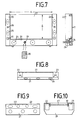
- FIG. 7 two vertically arranged housing parts 22, 23 are arranged on a horizontally arranged foot part 21 at a distance A.
- the foot part 21 contains low-frequency loudspeakers 24, while the housing parts 22, 23 contain broadband loudspeakers 25 and high-frequency loudspeakers 26.
- a screen 27 for projecting an image from a television projector, a slide projector, a film projector or the like is arranged in the opening formed by the parts 21, 22, 23.
- the canvas 27 can be lowered into the foot part 21 via a winding device 28.
- the foot part 1 contains an infrared receiver 29 for the signals of a remote control unit 30, with which parameters of the sound reproduction such as volume, treble, bass and stereo balance can be remotely controlled via actively designed boxes.
- lights 31 are provided in the foot part 21 or the housing parts 22, 23, and the brightness can also be controlled or switched on and off with the remote control unit 30.
- FIG. 8 is a top view of the arrangement according to FIG. 7.
- the screen 7 is tightly clamped between the housing parts 22, 23.
- the foot part 21 and the housing parts 22, 23 are combined to form a compact unit, the canvas 27 being sunk in the foot part 21.
- FIG. 10 shows a top view of how the screen 27 is guided on the housing parts 22, 23 by means of guides 32, so that it is as flat as possible for a perfect image projection and does not become wavy.
- the housing parts 22, 23 can be designed so that they can be placed on the foot part 21 at different distances A in order to enable the placement of screens with different aspect ratios A / B.
- the following values are essentially considered for the aspect ratio FROM application 4: 3 Television, super 8 projection 5: 3 5: 4 16: 9 HDTV projection 36:24 Slide projection
- the canvas 27 is provided with a piezopolymeric film extending over the entire surface or a part of the surface, or is itself designed as such a film.
- a piezopolymeric film forms a membrane with a piezoelectrically controllable thickness and can additionally serve as a loudspeaker, in particular as a mid-range loudspeaker.
- the changes in thickness of the film when acting as a loudspeaker membrane are only a few ⁇ m and ha ben no negative influence on the image reproduction.
- the film is preferably divided along a vertical center line into two separate films, each of which forms a loudspeaker for stereo sound reproduction.
- the film serving as a loudspeaker can also be arranged behind the screen 27 in the viewing direction.
- the projection screen can be a normal screen or can also consist of plastic or some other plastic. It can also be a clear wall that is suitable for rear projection. A magnifying lens for the image, a so-called Fresnel lens, can also be arranged on the projection screen.
- the projection screen can be a rigid wall or can also be designed to be windable.
Landscapes
- Engineering & Computer Science (AREA)
- Signal Processing (AREA)
- Physics & Mathematics (AREA)
- Acoustics & Sound (AREA)
- Multimedia (AREA)
- General Physics & Mathematics (AREA)
- Overhead Projectors And Projection Screens (AREA)
- Piezo-Electric Transducers For Audible Bands (AREA)
- Details Of Audible-Bandwidth Transducers (AREA)
Abstract
Description
- Die Erfindung geht aus von einem Lautsprecher gemäß dem Oberbegriff des Anspruchs 1.
- Derartige als Wandler dienende Folien benötigen für einen ausreichenden Wirkungsgrad eine relativ große Fläche wie z.B. die Oberfläche einer Kugel.
- Der Erfindung liegt die Aufgabe zugrunde, einen Lautsprecher mit einer piezopolymeren Folie als Wandler zu schaffen, der praktisch keinen zusätzlichen Platzbedarf fordert.
- Diese Aufgabe wird durch die im Anspruch 1 beschriebene Erfindung gelöst. Vorteilhafte Weiterbildungen der Erfindung sind in den Unteransprüchen beschrieben.
- Die Folie wird also auf eine transparente Scheibe, insbesondere eine Glasfläche, aufgebracht, die ohnehin für einen Lichtdurchtritt, eine Bildbetrachtung, eine Bilddarstellung oder dgl. erforderlich ist. Der Platzbedarf für den Lautsprecher ist daher praktisch gleich null.
- Gemäß einer bevorzugten, besonders vorteilhaften Ausführungsform die bei einem Fernsehempfänger oder einem Monitor die transparente Folie auf den Bildschirm aufgebracht. Dabei ergeben sich mehrere Vorteile. Am Gehäuse des Fernsehempfängers wird für den Lautsprecher kein zusätzlicher Platz mehr benötigt, so daß sich neuartige Möglichkeiten beim Design eines Fernsehempfängers eröffnen. Es kommt zu einer optimalen Übereinstimmung in der räumlichen Lage von Bildquelle und Tonquelle, da Bild und Ton exakt von derselben Fläche, nämlich dem Bildschirm des Fernsehempfänger ausgehen. Ein solcher Lautsprecher mit einer piezopolymeren Folie hat insbesondere bei einem Fernsehempfänger den Vorteil, daß er kein Magnetfeld erzeugt, das die Ablenkung in der Bildröhre stören könnte.
- Die Erfindung ist auch anwendbar bei üblichen Bildern, wie sie allgemein in Wohnräumen zu finden sind. Dann kann die ohnehin von dem Bild an der Wand eingenommene Fläche zusätzlich als Lautsprecher dienen. Der Lautsprecher kann auch auf sonstigen Scheiben wie Autofenstern, Flugzeugfenstern, Leuchten, Lampen, Brillengläsern, Meßgeräten, Uhren und dgl. realisiert werden. Vorzugsweise ist die Folie auf eine Glasscheibe aufgebracht. Die Erfindung ist aber auch anwendbar, wenn eine Glasscheibe nicht unbedingt erforderlich ist. Bei einem Bild ohne Glasscheibe kann die Folie auch unmittelbar auf die eigentliche Bildvorlage aufgebracht werden. Die Folie hat eine derartige Transparenz, daß der Lichtdurchtritt oder die Betrachtung eines hinter der Folie liegenden Bildes praktisch nicht gestört wird, die Folie also vom Betrachter gar nicht wahrgenommen wird Durch die Erfindung werden also für eine derartige transparente piezopolymere Folie neuartige, verteilhafte Anwendungsgebiete erschlossen.
- Die Erfindung wird anhand der Zeichnung erläutert. Darin zeigen
- Fig. 1 ein Beispiel für einen Fernsehempfänger,
- Fig. 2 eine Beispiel für ein Bild,
- Fig. 3 eine Weiterbildung der Erfindung für einen Lautsprecher zur Steuerung mit einem digitalen Tonsignal,
- Fig. 4 eine Weiterbildung von Fig 3 mit ringförmigen Folien,
- Fig. 5 einen Ausschnitt aus Fig. 4 mit maßstäblichem Flächenverhältnis,
- Fig. 6 eine Weiterbildung von Fig. 5 für einen Fernsehempfänger,
- Fig. 7 ein weiteres Ausführungsbeispiel der Erfindung und
- Fig. 8 - 10 verschiedene Ansichten von Fig. 7.
- Fig. 1 zeigt einen Fernsehempfänger 1 mit dem Bildschirm 2 und den Bedienelementen 3. Auf den Bildschirm 2 ist die symbolisch kreuzschraffiert dargestellte, in Wirklichkeit nicht erkennbare transparente piezopolymere Folie 4 aufgebracht, die sich über den ganzen Bildschirm 2 erstreckt. Die dem Bildschirm 2 zugewandte Seite der Folie 4 ist mit dem Massepotential des Fernsehempfängers verbunden. Die Folie 4 ist an zwei Stellen, insbesondere außerhalb des sichtbaren Bildschirmbereiches kontaktiert. An die dadurch gebildeten Klemmen 5 ist das zur Bildwiedergabe gehörende NF-Tonsignal angelegt. Ein zusätzlicher Lautsprecher links, rechts oder unterhalb des Bildschirms 2 ist nicht mehr erforderlich.
- Fig. 2 zeigt ein Bild mit dem Rahmen 6, der eigentlichen Bildvorlage 7 und der die Bildvorlage 7 abdeckenden Glasscheibe 8. Auf die Glasscheibe ist die transparente, als Lautsprecher dienende piezopolymere Folie 4 aufgebracht, die wie in Fig. 1 von den Klemmen 5 mit einem NF-Tonsignal gesteuert wird und als Lautsprecher dient. In den Rahmen 6 ist noch ein Einstellmittel 9 für die Lautstärke des durch die Folie 4 erzeugten Schallfeldes eingebaut.
- Fig. 3 zeigt eine Weiterbildung zur Steuerung des Lautsprechers mit einem digitalen Tonsignal. Die Folie 4 ist in eine Vielzahl von Einzelfolien aufgeteilt deren Flächenverhältnisse in Zweierpotenzen abgestuft sind. Die Flächen der ein zelnen Teilfolien haben also Werte von x, 2x, 4x, 8x, 16x, 32x, 64x, 128x. An die einzelnen, je einen Lautsprecher bildenden Teilfolien sind die unterschiedlich wertigen Bits eine Digitalsignals angelegt. Die Teilfolien erzeugen somit entsprechend dem digitalen Signal je ein Schallfeld. Vom Zuhörer wird die Summe der von den einzelnen Teilfolien ausgehenden Schallfelder wahrgenommen, die dem eigentlichen analogen Tonsignal entspricht. Ein derartiger Lautsprecher wirkt quasi als mechanischer Digital-Analog-Wandler.
- Fig. 4 zeigt eine Weiterbildung, bei der die Realisierung von Folien mit derart unterschiedlichen Flächen vereinfacht ist. Die einzelnen Folien liegen nicht in Form von Rechtekken nebeneinander, sondern sind als ringförmige, konzentrische Folien 10, 11, 12, 13, 14 ausgebildet, die auf einer Grundplatte 19 angeordnet sind und jeweils einen kleinen Abstand a von etwa 1 mm aufweisen. Da der jeweilige Radius r quadratisch in die Fläche eingeht, kann die Abstufung in der Fläche gemäß Fig. 4 besser realisiert werden. Wenn n die Ordnungszahl einer Folie und F die jeweilige Fläche der Folie ist, gilt allgemein die Beziehung Fn = 2 * Fn-1 = 2n-1 * F₁. In Fig. 4 sind die dargestellten Flächen nicht maßstabsgerecht, entsprechen also nicht der geforderten Zweierpotenz.
- Fig. 5 zeigt einen allseitig abgebrochenen, sektorförmigen Ausschnitt aus einer Anordnung gemäß Fig. 4, bei der die Flächen der einzelnen Folien 10 bis 18 maßstabsgerecht entsprechend der Zweierpotenz dargestellt sind
- Für ein Ausführungsbeispiel mit acht ringförmigen, konzentrischen Folien 10 bis 17 für ein acht-Bit-digitales Tonsignal ergeben sich für die Ordnungszahl n, den jeweils äußeren Radius r einer Folie und den Abstand a zwischen zwei benachbarten Folien folgende Werte:
n r (mm) r+a (mm) 1 2 3 2 6,02 7,02 3 13,07 14,07 4 25,57 26,57 5 47,77 48,77 6 87,18 88,18 7 157,11 158,11 8 281,18 282,18 - In Fig. 6 ist der Bildschirm 20 eines Fernsehempfängers durch eine Diagonale in zwei etwa dreieckförmige Flächen aufgeteilt. Jede dieser beiden dreieckförmigen Flächen enthält fünf segmentförmige Folien 10 bis 14 gemäß Fig. 5. Die beiden dreieckförmigen, einander gleichen Anordnungen können dann zur Wiedergabe eines Stereo-Tonsignals dienen.
- In Fig. 7 sind auf einem waagerecht angeordneten Fußteil 21 im Abstand A zwei senkrecht stehende Gehäuseteile 22, 23 angeordnet. Das Fußteil 21 enthält Tiefton-Lautsprecher 24, während die Gehäuseteile 22 ,23 Breitband-Lautsprecher 25 und Hochton-Lautsprecher 26 enthalten. In der durch die Teile 21, 22, 23 gebildeten Öffnung ist eine Leinwand 27 für die Projektion eines Bildes von einem Fernsehprojektor, einem Diaprojektor, einem Filmprojektor oder dgl. angeordnet. Die Leinwand 27 ist über eine Aufwickelvorrichtung 28 in dem Fußteil 21 versenkbar. Das Fußteil 1 enthält einen Infrarot-Empfänger 29 für die Signale einer Fernbedieneinheit 30, mit der über aktiv ausgebildete Boxen Parameter der Tonwiedergabe wie Lautstärke, Höhen, Tiefen und Stereobalance fernbedienbar sind. Außerdem sind in dem Fußteil 21 oder den Gehäuseteilen 22, 23 Leuchten 31 vorgesehen, die ebenfalls mit der Fernbedieneinheit 30 in der Helligkeit gesteuert oder ein- und ausgeschaltet werden können.
- Fig. 8 ist eine Draufsicht auf die Anordnung nach Fig. 7. Die Leinwand 7 ist stramm zwischen den Gehäuseteilen 22, 23 eingespannt.
- In Fig. 9 sind das Fußteil 21 und die Gehäuseteile 22, 23 zu einer kompakten Einheit zusammengelegt, wobei die Leinwand 27 in dem Fußteil 21 versenkt ist.
- Fig. 10 zeigt in einer Draufsicht, wie die Leinwand 27 mittels Führungen 32 an den Gehäuseteilen 22, 23 geführt ist, damit sie für eine einwandfreie Bildprojektion möglichst in einer Ebene liegt und nicht wellig wird.
- Die Gehäuseteile 22, 23 können in unterschiedlichen Abständen A auf das Fußteil 21 aufsetzbar ausgebildet sein, um die Unterbringung von Leinwänden mit unterschiedlichem Seitenverhältnis A/B zu ermöglichen. In der Praxis kommen im wesentlichen für das Seitenverhältnis folgende Werte in Betracht
A/B Anwendung 4:3 Fernsehen, Super-8-Projektion 5:3 5:4 16:9 HDTV-Projektion 36:24 Diaprojektion - Gemäß einer Weiterbildung ist die Leinwand 27 mit einer sich über die gesamte Fläche oder einen Teil der Fläche erstrekkenden piezopolymeren Folie versehen oder selbst als eine solche Folie ausgebildet. Eine solche Folie bildet eine Membran mit einer piezoelektrisch steuerbaren Dicke und kann zusätzlich als Lautsprecher, insbesondere als Mitteltonlautsprecher dienen. Die Dickeänderungen der Folie bei der Wirkung als Lautsprechermembran betragen nur wenige µm und ha ben auf die Bildwiedergabe keinen nachteiligen Einfluß. Dabei ist die Folie vorzugsweise entlang einer senkrechten Mittellinie in zwei getrennte Folien aufgeteilt, die je einen Lautsprecher für eine Stereo-Tonwiedergabe bilden. Die als Lautsprecher dienende Folie kann auch im Blickrichtung hinter der Leinwand 27 angeordnet sein. Es ist auch möglich, die gesamte Fläche der Leinwand 27 in eine größere Zahl getrennter piezopolymerer Folien aufzuteilen, die je einen elektrostatischen Lautsprecher für unterschiedliche Frequenzbereiche oder Kanäle einer Mehrkanal-Tonwiedergabe darstellen. Diese Lösung hat den Vorteil, daß die durch die Leinwand 27 eingenommene Fläche zusätzlich als Lautsprecher dient und somit der sonst für die Mittelton-Lautsprecher eingenommene Platz der gesamten Einrichtung eingespart wird. Gegebenenfalls können dann die beiden Gehäuseteile 22, 23 kleiner ausgebildet sein, nur als Stütze für die Leinwand 27 dienen oder ganz entfallen, wenn die Leinwand selbsttragend ausgebildet ist.
- Die Projektionswand kann eine übliche Leinwand sein oder auch aus Kunststoff oder einem sonstigen Plastik bestehen. Es kann sich auch um eine durchsichtige Wand handeln, die für eine Rückprojektion geeignet ist. Auf der Projektionswand kann zusätzlich eine Vergrößerungslinse für das Bild, eine sogenannte Fresnel-Linse angeordnet sein. Die Projektionswand kann eine starre Wand sein oder auch aufwickelbar ausgebildet sein.
Claims (10)
Applications Claiming Priority (6)
| Application Number | Priority Date | Filing Date | Title |
|---|---|---|---|
| DE3832616 | 1988-09-26 | ||
| DE3832617A DE3832617A1 (de) | 1988-09-26 | 1988-09-26 | Lautsprecher fuer ein digitales steuersignal |
| DE3832616A DE3832616A1 (de) | 1988-09-26 | 1988-09-26 | Lautsprecher |
| DE3832617 | 1988-09-26 | ||
| DE3915626 | 1989-05-12 | ||
| DE3915626 | 1989-05-12 |
Publications (2)
| Publication Number | Publication Date |
|---|---|
| EP0361249A1 true EP0361249A1 (de) | 1990-04-04 |
| EP0361249B1 EP0361249B1 (de) | 1992-03-25 |
Family
ID=27198275
Family Applications (2)
| Application Number | Title | Priority Date | Filing Date |
|---|---|---|---|
| EP89910614A Pending EP0435914A1 (de) | 1988-09-26 | 1989-09-16 | Lautsprecher |
| EP89117183A Expired - Lifetime EP0361249B1 (de) | 1988-09-26 | 1989-09-16 | Bild-Tonwiedergabegerät |
Family Applications Before (1)
| Application Number | Title | Priority Date | Filing Date |
|---|---|---|---|
| EP89910614A Pending EP0435914A1 (de) | 1988-09-26 | 1989-09-16 | Lautsprecher |
Country Status (9)
| Country | Link |
|---|---|
| US (1) | US5400414A (de) |
| EP (2) | EP0435914A1 (de) |
| JP (1) | JPH04501046A (de) |
| KR (1) | KR0126138B1 (de) |
| DE (1) | DE58901033D1 (de) |
| ES (1) | ES2031328T3 (de) |
| GR (1) | GR3005002T3 (de) |
| HU (1) | HU206579B (de) |
| WO (1) | WO1990003711A1 (de) |
Cited By (8)
| Publication number | Priority date | Publication date | Assignee | Title |
|---|---|---|---|---|
| EP0599250A2 (de) * | 1992-11-24 | 1994-06-01 | Canon Kabushiki Kaisha | Akustische Ausgabeeinrichtung, und elektronische Anordnung mit solch einer Einrichtung |
| WO1995008905A1 (en) * | 1993-09-20 | 1995-03-30 | Kuopion Teknologiakeskus Teknia Oy | Method for repeating of a sound |
| NL1000275C2 (nl) * | 1995-05-02 | 1996-11-05 | Hollandse Signaalapparaten Bv | Acoustische trillingsgenerator. |
| EP0773677A2 (de) * | 1995-11-11 | 1997-05-14 | Deutsche Telekom AG | Verfahren zur lokalen Verknüpfung von optischen und akustischen Signalen |
| WO2000002417A1 (en) * | 1998-07-03 | 2000-01-13 | New Transducers Limited | Resonant panel-form loudspeaker |
| WO2000067476A1 (en) * | 1999-04-28 | 2000-11-09 | Koninklijke Philips Electronics N.V. | Housing having a loudspeaker system |
| WO2002019764A1 (en) * | 2000-09-02 | 2002-03-07 | University Of Warwick | Electrostatic audio loudspeakers |
| DE20114680U1 (de) * | 2001-09-06 | 2003-01-16 | G + B pronova GmbH, 51427 Bergisch Gladbach | Projektionsschirm |
Families Citing this family (31)
| Publication number | Priority date | Publication date | Assignee | Title |
|---|---|---|---|---|
| US5517570A (en) * | 1993-12-14 | 1996-05-14 | Taylor Group Of Companies, Inc. | Sound reproducing array processor system |
| US5828768A (en) * | 1994-05-11 | 1998-10-27 | Noise Cancellation Technologies, Inc. | Multimedia personal computer with active noise reduction and piezo speakers |
| US5638456A (en) * | 1994-07-06 | 1997-06-10 | Noise Cancellation Technologies, Inc. | Piezo speaker and installation method for laptop personal computer and other multimedia applications |
| JP3830563B2 (ja) * | 1995-08-18 | 2006-10-04 | ソニー株式会社 | パネルシートとテレビジョン受像機 |
| US6266426B1 (en) | 1995-09-02 | 2001-07-24 | New Transducers Limited | Visual display means incorporating loudspeakers |
| KR19990044067A (ko) | 1995-09-02 | 1999-06-25 | 에이지마. 헨리 | 벤딩기계 |
| US6169809B1 (en) * | 1996-09-02 | 2001-01-02 | New Transducers Limited | Visual display means incorporating loudspeakers |
| BR9914480A (pt) | 1998-09-04 | 2001-06-26 | Ciba Sc Holding Ag | Processo para a fabricação de absorvedores de uv de 1,3,5-triazina substituìda por 2-hidróxi-4-alcoxifenila ou 2,4-didroxifenila |
| JP2000092578A (ja) | 1998-09-09 | 2000-03-31 | Fujitsu Ltd | スピーカ装置 |
| GB2358546B (en) * | 1998-11-13 | 2002-01-23 | Nec Corp | Piezoelectric diaphragm and piezoelectric speaker |
| JP3597061B2 (ja) * | 1998-11-13 | 2004-12-02 | 日本電気株式会社 | 圧電スピーカ |
| US6795561B1 (en) | 1999-07-08 | 2004-09-21 | New Transducers Limited | Panel drive |
| US6199655B1 (en) * | 1999-10-22 | 2001-03-13 | American Technology Corporation | Holographic transparent speaker |
| US6791519B2 (en) * | 2001-04-04 | 2004-09-14 | Koninklijke Philips Electronics N.V. | Sound and vision system |
| US7280087B2 (en) | 2001-04-23 | 2007-10-09 | Gilbarco Inc. | Multiple browser interface |
| US6493440B2 (en) | 2001-04-23 | 2002-12-10 | Gilbarco Inc. | Thermal management for a thin environmentally-sealed LCD display enclosure |
| US6708797B2 (en) * | 2001-04-23 | 2004-03-23 | Gilbarco Inc. | Display enclosure having thin speaker |
| EP1274272A1 (de) * | 2001-06-19 | 2003-01-08 | Chao-Hsien Lin | Anwendung eines unsichtbaren Lautsprechers und Verfahren zu seiner Herstellung |
| KR100435850B1 (ko) * | 2001-12-11 | 2004-06-10 | 타이 얀 캄 | 평판 스피커 |
| US7426804B2 (en) * | 2002-02-06 | 2008-09-23 | Andersen Corporation | Specialty display window |
| US7180489B2 (en) * | 2002-02-06 | 2007-02-20 | Andersen Corporation | Automated multi-task window assembly |
| US7109959B2 (en) | 2002-02-06 | 2006-09-19 | Andersen Corporation | Multi-task window |
| JP2003274314A (ja) * | 2002-03-13 | 2003-09-26 | Seiko Epson Corp | リアプロジェクタ、およびその製造方法 |
| KR100687112B1 (ko) * | 2002-03-15 | 2007-02-27 | 샤프 가부시키가이샤 | 영상 표시 장치 |
| US20040038722A1 (en) * | 2002-08-22 | 2004-02-26 | Michael Gauselmann | Gaming machine having a distributed mode acoustic radiator |
| FR2853802B1 (fr) * | 2003-04-11 | 2005-06-24 | Pierre Denis Rene Vincent | Installation pour la projection d'oeuvres cinematographiques ou numeriques sonores |
| SG125087A1 (en) * | 2003-05-21 | 2006-09-29 | Sony Corp | A sound and vision generation system |
| JP2005185502A (ja) * | 2003-12-25 | 2005-07-14 | Samii Kk | 遊技機 |
| SG134188A1 (en) * | 2006-01-11 | 2007-08-29 | Sony Corp | Display unit with sound generation system |
| WO2014157351A1 (ja) * | 2013-03-28 | 2014-10-02 | 富士フイルム株式会社 | 電気音響変換フィルム、電気音響変換器、フレキシブルディスプレイおよびプロジェクター用スクリーン |
| WO2016002677A1 (ja) * | 2014-06-30 | 2016-01-07 | 富士フイルム株式会社 | 電気音響変換フィルムおよびデジタルスピーカ |
Citations (5)
| Publication number | Priority date | Publication date | Assignee | Title |
|---|---|---|---|---|
| CH539845A (de) * | 1972-06-30 | 1973-07-31 | Ibm | Elektroakustischer Wandler |
| FR2383461A1 (fr) * | 1977-03-09 | 1978-10-06 | Mechanische Weberei Gmbh | Ecran de projection avec haut-parleurs |
| GB2052919A (en) * | 1979-06-15 | 1981-01-28 | Hitachi Ltd | Transparent flat panel speaker |
| GB2081948A (en) * | 1980-08-08 | 1982-02-24 | Sony Corp | Remote control arrangements |
| DE3223615A1 (de) * | 1982-06-24 | 1983-12-29 | Siemens AG, 1000 Berlin und 8000 München | Elektromechanischer wandler |
Family Cites Families (1)
| Publication number | Priority date | Publication date | Assignee | Title |
|---|---|---|---|---|
| JPS6161598A (ja) * | 1984-09-03 | 1986-03-29 | Matsushita Electric Ind Co Ltd | 音響装置 |
-
1989
- 1989-09-16 JP JP1509956A patent/JPH04501046A/ja active Pending
- 1989-09-16 DE DE8989117183T patent/DE58901033D1/de not_active Expired - Fee Related
- 1989-09-16 WO PCT/EP1989/001076 patent/WO1990003711A1/de not_active Application Discontinuation
- 1989-09-16 EP EP89910614A patent/EP0435914A1/de active Pending
- 1989-09-16 ES ES198989117183T patent/ES2031328T3/es not_active Expired - Lifetime
- 1989-09-16 KR KR1019900701088A patent/KR0126138B1/ko not_active IP Right Cessation
- 1989-09-16 EP EP89117183A patent/EP0361249B1/de not_active Expired - Lifetime
- 1989-09-16 HU HU895540A patent/HU206579B/hu not_active IP Right Cessation
- 1989-09-26 US US07/678,351 patent/US5400414A/en not_active Expired - Fee Related
-
1992
- 1992-06-23 GR GR920401342T patent/GR3005002T3/el unknown
Patent Citations (5)
| Publication number | Priority date | Publication date | Assignee | Title |
|---|---|---|---|---|
| CH539845A (de) * | 1972-06-30 | 1973-07-31 | Ibm | Elektroakustischer Wandler |
| FR2383461A1 (fr) * | 1977-03-09 | 1978-10-06 | Mechanische Weberei Gmbh | Ecran de projection avec haut-parleurs |
| GB2052919A (en) * | 1979-06-15 | 1981-01-28 | Hitachi Ltd | Transparent flat panel speaker |
| GB2081948A (en) * | 1980-08-08 | 1982-02-24 | Sony Corp | Remote control arrangements |
| DE3223615A1 (de) * | 1982-06-24 | 1983-12-29 | Siemens AG, 1000 Berlin und 8000 München | Elektromechanischer wandler |
Non-Patent Citations (2)
| Title |
|---|
| PATENT ABSTRACTS OF JAPAN, Band 10, Nr. 228 (E-426)[2284], 8. August 1986; & JP-A-61 61 598 (MATSUSHITA ELECTRIC IND. CO., LTD) 29-03-1986 * |
| PATENT ABSTRACTS OF JAPAN, Band 9, Nr. 43 (E-298)[1766], 22. Februar 1985; & JP-A-59 183 581 (MATSUSHITA DENKI SANGYO K.K.) 18-10-1984 * |
Cited By (14)
| Publication number | Priority date | Publication date | Assignee | Title |
|---|---|---|---|---|
| EP0599250A3 (de) * | 1992-11-24 | 1995-07-26 | Canon Kk | Akustische Ausgabeeinrichtung, und elektronische Anordnung mit solch einer Einrichtung. |
| EP0599250A2 (de) * | 1992-11-24 | 1994-06-01 | Canon Kabushiki Kaisha | Akustische Ausgabeeinrichtung, und elektronische Anordnung mit solch einer Einrichtung |
| WO1995008905A1 (en) * | 1993-09-20 | 1995-03-30 | Kuopion Teknologiakeskus Teknia Oy | Method for repeating of a sound |
| NL1000275C2 (nl) * | 1995-05-02 | 1996-11-05 | Hollandse Signaalapparaten Bv | Acoustische trillingsgenerator. |
| WO1996035313A1 (en) * | 1995-05-02 | 1996-11-07 | Hollandse Signaalapparaten B.V. | Acoustic vibration generator |
| EP0773677A3 (de) * | 1995-11-11 | 2000-03-22 | Deutsche Telekom AG | Verfahren zur lokalen Verknüpfung von optischen und akustischen Signalen |
| EP0773677A2 (de) * | 1995-11-11 | 1997-05-14 | Deutsche Telekom AG | Verfahren zur lokalen Verknüpfung von optischen und akustischen Signalen |
| WO2000002417A1 (en) * | 1998-07-03 | 2000-01-13 | New Transducers Limited | Resonant panel-form loudspeaker |
| US7174025B2 (en) | 1998-07-03 | 2007-02-06 | New Transducers Limited | Resonant panel-form loudspeaker |
| WO2000067476A1 (en) * | 1999-04-28 | 2000-11-09 | Koninklijke Philips Electronics N.V. | Housing having a loudspeaker system |
| WO2002019764A1 (en) * | 2000-09-02 | 2002-03-07 | University Of Warwick | Electrostatic audio loudspeakers |
| US7095864B1 (en) | 2000-09-02 | 2006-08-22 | University Of Warwick | Electrostatic audio loudspeakers |
| USRE40860E1 (en) | 2000-09-02 | 2009-07-21 | University Of Warwick | Electrostatic audio loudspeakers |
| DE20114680U1 (de) * | 2001-09-06 | 2003-01-16 | G + B pronova GmbH, 51427 Bergisch Gladbach | Projektionsschirm |
Also Published As
| Publication number | Publication date |
|---|---|
| KR900702746A (ko) | 1990-12-08 |
| KR0126138B1 (ko) | 1997-12-26 |
| WO1990003711A1 (de) | 1990-04-05 |
| HU895540D0 (en) | 1991-04-29 |
| EP0435914A1 (de) | 1991-07-10 |
| ES2031328T3 (es) | 1992-12-01 |
| US5400414A (en) | 1995-03-21 |
| EP0361249B1 (de) | 1992-03-25 |
| HU206579B (en) | 1992-11-30 |
| DE58901033D1 (de) | 1992-04-30 |
| JPH04501046A (ja) | 1992-02-20 |
| HUT59522A (en) | 1992-05-28 |
| GR3005002T3 (de) | 1993-05-24 |
Similar Documents
| Publication | Publication Date | Title |
|---|---|---|
| EP0361249A1 (de) | Bild-Tonwiedergabegerät | |
| DE69921295T2 (de) | Kontinuierliches Vlies mit Aluminiumfasern | |
| DE3856255T2 (de) | Videoanzeigesystem | |
| DE3414407A1 (de) | Einbau von schallwandlern in eine schallfuehrung, insbesondere fuer lautsprecher vorzugsweise fuer lautsprecherboxen | |
| EP0584752A2 (de) | Verfahren und Vorrichtung zur Erzeugung stereoskopischer Darstellungen | |
| EP0117487A1 (de) | Fernsehgerät mit internem Tieftonlautsprecher | |
| EP1078300B1 (de) | Projektionswand | |
| DE3832616A1 (de) | Lautsprecher | |
| EP1789834A1 (de) | Anordnung zur wahlweise dreidimensional wahrnehmbaren oder zweidimensionalen darstellung von bildern | |
| DE4033068A1 (de) | Fernsehempfangsgeraet mit stereotonwiedergabe | |
| DE2716063B2 (de) | Dynamischer Wandler mit einer Schwingspule in einem mit einer magnetischen Flüssigkeit gefüllten Luftspalt | |
| DE69523243T2 (de) | Audiovisuelle vorrichtung und diese anwendendes system | |
| EP0303912A2 (de) | Tiefton-Lautsprecherbox | |
| DE3312362C1 (de) | Gerät mit einem in der Helligkeit regelbaren Bildschirm und/oder Anzeigdisplay | |
| DE19542147A1 (de) | Verfahren zur lokalen Verknüpfung von optischen und akustischen Signalen | |
| WO2006048006A1 (de) | System zur wiedergabe von audiosignalen | |
| DE3727098A1 (de) | Tiefton-lautsprecherbox | |
| EP0372186B1 (de) | Lautsprecherboxen für Fernseh- und andere Geräte | |
| DE19642617C2 (de) | Anzeigeeinheit und Projektionsvorrichtung für Bildsequenzen | |
| WO1983004155A1 (en) | Stereoscopic television | |
| DE69125512T2 (de) | Tonausrüstung für einen Fernseher | |
| DE69806704T2 (de) | Monitor mit röhrenförmigen lautsprechern zur reduzierung der vibrationen der kathodenstrahlröhrenmaske | |
| DE3926535C2 (de) | ||
| EP0465902A2 (de) | Integrierte Fernsehlautsprecherbox | |
| DE3832617A1 (de) | Lautsprecher fuer ein digitales steuersignal |
Legal Events
| Date | Code | Title | Description |
|---|---|---|---|
| PUAI | Public reference made under article 153(3) epc to a published international application that has entered the european phase |
Free format text: ORIGINAL CODE: 0009012 |
|
| AK | Designated contracting states |
Kind code of ref document: A1 Designated state(s): ES GR |
|
| 17P | Request for examination filed |
Effective date: 19900906 |
|
| RBV | Designated contracting states (corrected) |
Designated state(s): DE ES FR GB GR IT |
|
| XX | Miscellaneous (additional remarks) |
Free format text: VERBUNDEN MIT 89910614.0/0435914 (EUROPAEISCHE ANMELDENUMMER/VEROEFFENTLICHUNGSNUMMER) DURCH ENTSCHEIDUNG VOM 07.08.91. |
|
| 17Q | First examination report despatched |
Effective date: 19910911 |
|
| GRAA | (expected) grant |
Free format text: ORIGINAL CODE: 0009210 |
|
| ITF | It: translation for a ep patent filed | ||
| AK | Designated contracting states |
Kind code of ref document: B1 Designated state(s): DE ES FR GB GR IT |
|
| XX | Miscellaneous (additional remarks) |
Free format text: VERBUNDEN MIT 89910614.0/0435914 (EUROPAEISCHE ANMELDENUMMER/VEROEFFENTLICHUNGSNUMMER) DURCH ENTSCHEIDUNG VOM 07.08.91. |
|
| REF | Corresponds to: |
Ref document number: 58901033 Country of ref document: DE Date of ref document: 19920430 |
|
| GBT | Gb: translation of ep patent filed (gb section 77(6)(a)/1977) | ||
| ET | Fr: translation filed | ||
| PGFP | Annual fee paid to national office [announced via postgrant information from national office to epo] |
Ref country code: GR Payment date: 19920916 Year of fee payment: 4 |
|
| REG | Reference to a national code |
Ref country code: ES Ref legal event code: FG2A Ref document number: 2031328 Country of ref document: ES Kind code of ref document: T3 |
|
| PLBE | No opposition filed within time limit |
Free format text: ORIGINAL CODE: 0009261 |
|
| STAA | Information on the status of an ep patent application or granted ep patent |
Free format text: STATUS: NO OPPOSITION FILED WITHIN TIME LIMIT |
|
| REG | Reference to a national code |
Ref country code: GR Ref legal event code: FG4A Free format text: 3005002 |
|
| 26N | No opposition filed | ||
| PG25 | Lapsed in a contracting state [announced via postgrant information from national office to epo] |
Ref country code: GR Free format text: THE PATENT HAS BEEN ANNULLED BY A DECISION OF A NATIONAL AUTHORITY Effective date: 19940331 |
|
| REG | Reference to a national code |
Ref country code: GR Ref legal event code: MM2A Free format text: 3005002 |
|
| REG | Reference to a national code |
Ref country code: GB Ref legal event code: 746 Effective date: 19971022 |
|
| REG | Reference to a national code |
Ref country code: GB Ref legal event code: IF02 |
|
| PGFP | Annual fee paid to national office [announced via postgrant information from national office to epo] |
Ref country code: GB Payment date: 20040805 Year of fee payment: 16 |
|
| PGFP | Annual fee paid to national office [announced via postgrant information from national office to epo] |
Ref country code: DE Payment date: 20040916 Year of fee payment: 16 |
|
| PGFP | Annual fee paid to national office [announced via postgrant information from national office to epo] |
Ref country code: FR Payment date: 20040922 Year of fee payment: 16 |
|
| PGFP | Annual fee paid to national office [announced via postgrant information from national office to epo] |
Ref country code: ES Payment date: 20040923 Year of fee payment: 16 |
|
| PG25 | Lapsed in a contracting state [announced via postgrant information from national office to epo] |
Ref country code: IT Free format text: LAPSE BECAUSE OF NON-PAYMENT OF DUE FEES;WARNING: LAPSES OF ITALIAN PATENTS WITH EFFECTIVE DATE BEFORE 2007 MAY HAVE OCCURRED AT ANY TIME BEFORE 2007. THE CORRECT EFFECTIVE DATE MAY BE DIFFERENT FROM THE ONE RECORDED. Effective date: 20050916 Ref country code: GB Free format text: LAPSE BECAUSE OF NON-PAYMENT OF DUE FEES Effective date: 20050916 |
|
| PG25 | Lapsed in a contracting state [announced via postgrant information from national office to epo] |
Ref country code: ES Free format text: LAPSE BECAUSE OF NON-PAYMENT OF DUE FEES Effective date: 20050917 |
|
| PG25 | Lapsed in a contracting state [announced via postgrant information from national office to epo] |
Ref country code: DE Free format text: LAPSE BECAUSE OF NON-PAYMENT OF DUE FEES Effective date: 20060401 |
|
| GBPC | Gb: european patent ceased through non-payment of renewal fee |
Effective date: 20050916 |
|
| PG25 | Lapsed in a contracting state [announced via postgrant information from national office to epo] |
Ref country code: FR Free format text: LAPSE BECAUSE OF NON-PAYMENT OF DUE FEES Effective date: 20060531 |
|
| REG | Reference to a national code |
Ref country code: FR Ref legal event code: ST Effective date: 20060531 |
|
| REG | Reference to a national code |
Ref country code: ES Ref legal event code: FD2A Effective date: 20050917 |