EP0360409A2 - Kupplungsscheibe mit durch eine Feder stossgedämpftem Reibbelag - Google Patents
Kupplungsscheibe mit durch eine Feder stossgedämpftem Reibbelag Download PDFInfo
- Publication number
- EP0360409A2 EP0360409A2 EP89308338A EP89308338A EP0360409A2 EP 0360409 A2 EP0360409 A2 EP 0360409A2 EP 89308338 A EP89308338 A EP 89308338A EP 89308338 A EP89308338 A EP 89308338A EP 0360409 A2 EP0360409 A2 EP 0360409A2
- Authority
- EP
- European Patent Office
- Prior art keywords
- disk assembly
- friction
- clutch disk
- driven clutch
- pair
- Prior art date
- Legal status (The legal status is an assumption and is not a legal conclusion. Google has not performed a legal analysis and makes no representation as to the accuracy of the status listed.)
- Withdrawn
Links
Images

Classifications
-
- F—MECHANICAL ENGINEERING; LIGHTING; HEATING; WEAPONS; BLASTING
- F16—ENGINEERING ELEMENTS AND UNITS; GENERAL MEASURES FOR PRODUCING AND MAINTAINING EFFECTIVE FUNCTIONING OF MACHINES OR INSTALLATIONS; THERMAL INSULATION IN GENERAL
- F16D—COUPLINGS FOR TRANSMITTING ROTATION; CLUTCHES; BRAKES
- F16D13/00—Friction clutches
- F16D13/58—Details
- F16D13/60—Clutching elements
- F16D13/64—Clutch-plates; Clutch-lamellae
- F16D2013/642—Clutch-plates; Clutch-lamellae with resilient attachment of frictions rings or linings to their supporting discs or plates for allowing limited axial displacement of these rings or linings
Definitions
- This invention relates to driven clutch disk assemblies adapted for use in dry friction clutches. More particularly, the invention relates to the use of cushioned friction systems within such disk assemblies for the purpose of reducing friction forces during initial clutch engagement.
- the conventional clutch disk assembly for automotive and other vehicular use includes a hub having a flanged portion secured to an integral flat disk.
- the disk typically has a plurality of friction pads riveted or bonded to its sides.
- the disk is positioned, by means of the hub on a transmission input shaft, between a flywheel and a reciprocal pressure plate driven by an internal combustion engine or electric motor.
- a clutch pedal Upon depression of a clutch pedal, the pressure plate is axially moved away from the flywheel to disengage the clutch, and, upon release of the pedal, the pressure plate moves the disk toward the flywheel to engage the disk between the pressure plate and flywheel.
- the driven clutch disk assembly of the present invention incorporates a spring cushioned friction element assembly which operates to reduce initial clutch engagement friction forces, hence to obviate the problem of chatter in dry friction clutches.
- the spring cushioned element assembly avoids initial full engagement of available friction area, and provides for a continuously increasing amount of clutch engaging friction material. At initial clutch engagement a small amount of clutching capacity is provided by means of an initial use of a smaller surface friction contact area than that totally available. As clutch engagement progresses, the contact area increases, thus achieving full available friction contact area at full clutch engagement.
- the spring cushioned friction element system of this invention thus provides a means for avoidance of aggressive or grabby clutching, and hence the chatter phenomena normally associated therewith.
- the driven clutch disk assembly of the present invention includes a unitary disk having a central aperture for accommodating securement of the disk to a hub for placement on a transmission input shaft.
- a plurality of secondary apertures are spaced radially outwardly of the central aperture, each secondary aperture defining a pair of circumferentially spaced radial boundaries.
- a pair of backing plates are each secured to opposite sides of each secondary aperture, each backing plate containing a friction element laminated or otherwise bonded to the plate.
- Each backing plate has an overlap portion secured along each side of the spaced radial boundaries of each secondary aperture.
- Each radial boundary of each secondary aperture contains an integral circumferentially extending cantilevered spring beam positioned between the pair of backing plates associated with that particular aperture.
- Each beam is spring loaded against one of the backing plates, and in the preferred form one of two beams is spring loaded against one backing plate, while the other beam is spring loaded against the other, opposing, backing plate.
- Each beam is disposed against the backing plate in a matter such that it applies a normal force producing elastic displacement of the backing plate and the friction element bonded to that plate.
- the friction element thus contains a slightly convex friction engagement surface, wherein the resultant "crowned" surface area will initially make contact with either the flywheel or pressure plate at the outermost extremity of the crown. As the crowned friction surface area collapses under clutch engagement, the full available friction surface area will gradually become engaged, thus presenting a variably increasing surface friction contact area as clutch engagement ensues.
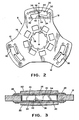
- a driven clutch disk assembly 10 is positioned between a flywheel and a reciprocal pressure plate (neither shown).
- the assembly 10 includes a unitary disk 8 having a plurality of radially extending segments or lobes 12 which emanate from a central disk portion 14.
- the portion 14 is secured to a central hub 18 by means of rivets 16, the hub being splined for installation on a transmission input shaft (not shown).
- each individual lobe 12 of the disk 8 incorporates an aperture 30.
- a pair of backing plates 20 are installed over each aperture 30, one backing plate secured to each side of one lobe 12.
- each associated set of backing plates is opposingly secured to one lobe 12 and to each other by means of the rivets 26; each rivet 26 extends through both backing plates as well as through the associated lobe 12.
- Each backing plate has a pair of circumferentially spaced overlap portions 24 secured along the radial sides of the aperture 30 in the associated lobe.
- a friction element 22 Secured by lamination or bonding to each backing plate is a friction element 22, wherein a pair of friction elements are associated with each lobe, one secured to each backing plate as will be appreciated by those skilled in the art.
- each aperture 30 includes a pair of spaced radially extending boundaries 32. Emanating circumferentially from each boundary 32 is a cantilevered spring beam 34, each beam having a backing plate contact portion 36.
- the portion 36 is radially arcuate in its preferred form, having its center positioned to lie on a radially extending line "a-a" which passes through the radial center of the secondary aperture 30 as well as through the center of the central aperture 38 of the central disk portion 14.
- the beams 34 are made of spring steel for greatest effectiveness.
- there are two of such beams 34 each extending from opposite or opposing boundaries 32 of the aperture 30.
- the beams will have extremities 40 which extend beyond each other, but must yet avoid interference or contact with each other.
- the beams in the preferred embodiment are radially off-set from each other.
- a preferred process for forming the unitary disk 8 is via stamping.
- the beams 34 are adapted to bear against the back sides of the associated backing plates 20.
- the net result will be that a slightly convex or crowned friction surface is established over the surface of the friction elements 22 for initial contact thereof with the flywheel and pressure plate members.
- the engaging surface of the friction elements 22 will be elastically displaced by virtue of a normal beam spring force to form a crowned surface.
- the convexity of the crowned surface will tend to decrease, and hence flatten out, during clutch engagement under the resilient cushioning force of the beam which is overcome by the clutch engagement forces.
- the arcuate backing plate contact area 36 of each beam will have its radial center coincident with the radius "a-a" which extends through the center of the secondary aperture 30.
- the convexity of the friction element 22 will be preferably symmetrical. Although symmetry is present in all dimensional aspects of the as-described embodiment of the present invention, this invention also contemplates asymmetrical convexities as falling within its scope.
- the present invention also contemplates the use of a friction element formed of a copper-ceramic material, preferably eighty (80) percent copper.
- a unitary disk 8 of 14 inches in diameter has a thickness in the range of 90-110 thousandths of an inch.
- Each backing plate has a thickness of 50 thousandths or half of the disk thickness, and is preferably formed of an SAE 10-30 steel material.
- Each copper-ceramic friction element has a thickness of approximately 100 thousandths of an inch, and is displaced convexly outwardly at its center-most point by approximately three to seven (3 to 7) thousandths of an inch for greatest effectiveness.
Landscapes
- Engineering & Computer Science (AREA)
- General Engineering & Computer Science (AREA)
- Mechanical Engineering (AREA)
- Mechanical Operated Clutches (AREA)
Applications Claiming Priority (2)
| Application Number | Priority Date | Filing Date | Title |
|---|---|---|---|
| US247018 | 1988-09-20 | ||
| US07/247,018 US4869356A (en) | 1988-09-20 | 1988-09-20 | Clutch disk with spring cushioned friction element |
Publications (2)
| Publication Number | Publication Date |
|---|---|
| EP0360409A2 true EP0360409A2 (de) | 1990-03-28 |
| EP0360409A3 EP0360409A3 (de) | 1991-01-09 |
Family
ID=22933206
Family Applications (1)
| Application Number | Title | Priority Date | Filing Date |
|---|---|---|---|
| EP19890308338 Withdrawn EP0360409A3 (de) | 1988-09-20 | 1989-08-17 | Kupplungsscheibe mit durch eine Feder stossgedämpftem Reibbelag |
Country Status (5)
| Country | Link |
|---|---|
| US (1) | US4869356A (de) |
| EP (1) | EP0360409A3 (de) |
| JP (1) | JPH02120516A (de) |
| KR (1) | KR900000612A (de) |
| BR (1) | BR8903394A (de) |
Cited By (2)
| Publication number | Priority date | Publication date | Assignee | Title |
|---|---|---|---|---|
| DE4319150A1 (de) * | 1992-06-18 | 1993-12-23 | Valeo | Kupplungsscheibe, insbesondere für eine Kraftfahrzeugkupplung |
| KR20160040591A (ko) * | 2013-08-07 | 2016-04-14 | 임-이니지아티브 메카니체 에스.알.엘. | 철도 차량의 디스크 브레이크용 마찰 재료 버튼을 지지하기 위한 플레이트 및 상기 플레이트를 포함하는 마찰 패드 |
Families Citing this family (11)
| Publication number | Priority date | Publication date | Assignee | Title |
|---|---|---|---|---|
| FR2663701B1 (fr) * | 1990-06-22 | 1992-11-27 | Valeo | Disque de friction, notamment pour embrayage. |
| US6015035A (en) * | 1997-12-03 | 2000-01-18 | Exedy Corporation | Clutch disk |
| US6155397A (en) * | 1999-09-09 | 2000-12-05 | Eaton Corporation | Clutch driven disc friction material mounting |
| US20040118645A1 (en) * | 2001-03-27 | 2004-06-24 | Eaton Corporation | Clutch driven disc friction material mounting |
| DE102005023332A1 (de) | 2005-05-17 | 2006-11-30 | Zf Friedrichshafen Ag | Kupplungsscheibe für eine Kupplungseinrichtung |
| DE102009019588A1 (de) * | 2008-05-16 | 2009-11-19 | Luk Lamellen Und Kupplungsbau Beteiligungs Kg | Nasskupplung |
| WO2014145227A1 (en) | 2013-03-15 | 2014-09-18 | Tech M3, Inc. | Wear resistant braking systems |
| AT515594A1 (de) * | 2014-04-01 | 2015-10-15 | Miba Frictec Gmbh | Federelement für eine Reibvorrichtung |
| US20170184164A1 (en) * | 2014-05-19 | 2017-06-29 | Tech M3, Inc | Brake Rotor With Working Surface Inserts |
| DE102015014396A1 (de) * | 2015-11-06 | 2017-05-11 | Man Truck & Bus Ag | Kupplungsscheibe für eine lösbare Drehmoment-Übertragungseinrichtung |
| AT521020B1 (de) * | 2018-04-16 | 2019-10-15 | Miba Frictec Gmbh | Kupplungsscheibe |
Citations (8)
| Publication number | Priority date | Publication date | Assignee | Title |
|---|---|---|---|---|
| DE625868C (de) * | 1933-10-27 | 1936-02-17 | Borg & Beck Company | Kupplungsreibscheibe |
| US2053622A (en) * | 1935-07-25 | 1936-09-08 | Gen Motors Corp | Clutch driven plate |
| US2194793A (en) * | 1936-08-01 | 1940-03-26 | Borg Warner | Clutch |
| US2566394A (en) * | 1948-06-22 | 1951-09-04 | Borg Warner | Clutch plate |
| FR1326139A (fr) * | 1962-06-22 | 1963-05-03 | Bendix Corp | Perfectionnements aux embrayages |
| US3526307A (en) * | 1968-07-29 | 1970-09-01 | Borg Warner | Friction member |
| GB2140881A (en) * | 1980-11-17 | 1984-12-05 | Borg Warner | Clutch driven plate assembly |
| DE3712647A1 (de) * | 1987-04-14 | 1988-11-03 | Fichtel & Sachs Ag | Kupplungsscheibe |
Family Cites Families (22)
| Publication number | Priority date | Publication date | Assignee | Title |
|---|---|---|---|---|
| US1492862A (en) * | 1923-02-05 | 1924-05-06 | Smith Sydney | Clutch |
| US1768997A (en) * | 1929-03-07 | 1930-07-01 | Borg & Beck Co | Clutch plate |
| US1837173A (en) * | 1929-03-07 | 1931-12-15 | Borg & Beck Co | Clutch plate |
| US1810360A (en) * | 1929-09-12 | 1931-06-16 | Int Motor Co | Clutch disk construction |
| US1868543A (en) * | 1930-04-03 | 1932-07-26 | Monmouth Products Company | Clutch plate |
| US1956828A (en) * | 1931-03-02 | 1934-05-01 | Continental Motors Corp | Clutch disk |
| US1931065A (en) * | 1931-04-17 | 1933-10-17 | Chrysler Corp | Clutch member |
| US2008169A (en) * | 1932-03-23 | 1935-07-16 | Gen Motors Corp | Clutch plate |
| US1949385A (en) * | 1932-06-27 | 1934-02-27 | Warner Gear Co | Clutch device |
| US2141164A (en) * | 1933-08-17 | 1938-12-27 | Automatic Drive & Transmission | Automatic clutch |
| US2101410A (en) * | 1933-12-11 | 1937-12-07 | Borg Warner | Clutch plate |
| US2107741A (en) * | 1934-10-31 | 1938-02-08 | Borg Warner | Clutch plate |
| US2244134A (en) * | 1938-02-10 | 1941-06-03 | Thelander W Vincent | Clutch plate |
| US2195666A (en) * | 1939-03-25 | 1940-04-02 | Gen Motors Corp | Friction clutch |
| US2613785A (en) * | 1947-07-10 | 1952-10-14 | Borg Warner | Clutch plate with vibration dampener |
| US2618369A (en) * | 1948-03-24 | 1952-11-18 | Borg Warner | Clutch driven plate |
| US2784105A (en) * | 1955-11-08 | 1957-03-05 | Bendix Aviat Corp | Friction lining compositions |
| US2986252A (en) * | 1957-10-02 | 1961-05-30 | Bendix Corp | Mounting for friction lining segments |
| US3027979A (en) * | 1959-04-16 | 1962-04-03 | Bendix Corp | Brake structure |
| US3164236A (en) * | 1961-06-22 | 1965-01-05 | Bendix Corp | Clutch plates and the like |
| US4375254A (en) * | 1980-11-17 | 1983-03-01 | Borg-Warner Corporation | Clutch driven plate assembly with cushioned friction material |
| US4565274A (en) * | 1983-03-30 | 1986-01-21 | Dana Corporation | Friction clutch element |
-
1988
- 1988-09-20 US US07/247,018 patent/US4869356A/en not_active Expired - Lifetime
-
1989
- 1989-06-29 KR KR1019890009098A patent/KR900000612A/ko not_active Application Discontinuation
- 1989-07-11 BR BR898903394A patent/BR8903394A/pt unknown
- 1989-08-17 EP EP19890308338 patent/EP0360409A3/de not_active Withdrawn
- 1989-09-20 JP JP1242368A patent/JPH02120516A/ja active Pending
Patent Citations (8)
| Publication number | Priority date | Publication date | Assignee | Title |
|---|---|---|---|---|
| DE625868C (de) * | 1933-10-27 | 1936-02-17 | Borg & Beck Company | Kupplungsreibscheibe |
| US2053622A (en) * | 1935-07-25 | 1936-09-08 | Gen Motors Corp | Clutch driven plate |
| US2194793A (en) * | 1936-08-01 | 1940-03-26 | Borg Warner | Clutch |
| US2566394A (en) * | 1948-06-22 | 1951-09-04 | Borg Warner | Clutch plate |
| FR1326139A (fr) * | 1962-06-22 | 1963-05-03 | Bendix Corp | Perfectionnements aux embrayages |
| US3526307A (en) * | 1968-07-29 | 1970-09-01 | Borg Warner | Friction member |
| GB2140881A (en) * | 1980-11-17 | 1984-12-05 | Borg Warner | Clutch driven plate assembly |
| DE3712647A1 (de) * | 1987-04-14 | 1988-11-03 | Fichtel & Sachs Ag | Kupplungsscheibe |
Cited By (3)
| Publication number | Priority date | Publication date | Assignee | Title |
|---|---|---|---|---|
| DE4319150A1 (de) * | 1992-06-18 | 1993-12-23 | Valeo | Kupplungsscheibe, insbesondere für eine Kraftfahrzeugkupplung |
| DE4319150C2 (de) * | 1992-06-18 | 2003-08-28 | Valeo | Kupplungsscheibe, insbesondere für eine Kraftfahrzeugkupplung |
| KR20160040591A (ko) * | 2013-08-07 | 2016-04-14 | 임-이니지아티브 메카니체 에스.알.엘. | 철도 차량의 디스크 브레이크용 마찰 재료 버튼을 지지하기 위한 플레이트 및 상기 플레이트를 포함하는 마찰 패드 |
Also Published As
| Publication number | Publication date |
|---|---|
| JPH02120516A (ja) | 1990-05-08 |
| EP0360409A3 (de) | 1991-01-09 |
| BR8903394A (pt) | 1990-04-17 |
| KR900000612A (ko) | 1990-01-30 |
| US4869356A (en) | 1989-09-26 |
Similar Documents
| Publication | Publication Date | Title |
|---|---|---|
| US4676356A (en) | Multiple rotating disk assembly with elastic separator means | |
| US4869356A (en) | Clutch disk with spring cushioned friction element | |
| US4583959A (en) | Damper disc | |
| US4646900A (en) | Friction material and carrier plate assembly | |
| US4485909A (en) | Multiple stage vibration damper | |
| JPH0631226Y2 (ja) | クラッチディスク | |
| US4257510A (en) | Non-linear spring rate clutch damper | |
| GB2140881A (en) | Clutch driven plate assembly | |
| GB2141190A (en) | Clutch driven plate assembly with axial resilience | |
| EP0147136B1 (de) | Schwingungsdämpfer einfacher Konstruktion | |
| CN218787268U (zh) | 一种具有扭矩限制器的动力总成 | |
| US4671399A (en) | Friction facing assembly | |
| US2888122A (en) | Clutch plate | |
| WO2018109129A1 (en) | A torque limiter having a drive plate | |
| US5401213A (en) | Clutch and damper assembly | |
| EP0159339B1 (de) | Schwungrad für brennkraftmotor | |
| US6354419B1 (en) | Clutch mechanism with wear take-up device comprising balancing means | |
| EP0285300A1 (de) | Reibelement für Kupplung | |
| GB1569436A (en) | One-piece stamped clutch hub | |
| US3964586A (en) | Clutch disc | |
| US5601173A (en) | Liner support disc for supporting friction liners, especially for a motor vehicle | |
| GB1587209A (en) | Fabricated clutch pressure plate | |
| US4270640A (en) | Friction clutch driven plates | |
| US8430222B2 (en) | Friction clutch system | |
| GB1572946A (en) | Driven clutch plate assemblies |
Legal Events
| Date | Code | Title | Description |
|---|---|---|---|
| PUAI | Public reference made under article 153(3) epc to a published international application that has entered the european phase |
Free format text: ORIGINAL CODE: 0009012 |
|
| AK | Designated contracting states |
Kind code of ref document: A2 Designated state(s): DE FR GB SE |
|
| PUAL | Search report despatched |
Free format text: ORIGINAL CODE: 0009013 |
|
| AK | Designated contracting states |
Kind code of ref document: A3 Designated state(s): DE FR GB SE |
|
| STAA | Information on the status of an ep patent application or granted ep patent |
Free format text: STATUS: THE APPLICATION IS DEEMED TO BE WITHDRAWN |
|
| 18D | Application deemed to be withdrawn |
Effective date: 19910710 |