EP0360168B1 - Machine tool - Google Patents
Machine tool Download PDFInfo
- Publication number
- EP0360168B1 EP0360168B1 EP89117100A EP89117100A EP0360168B1 EP 0360168 B1 EP0360168 B1 EP 0360168B1 EP 89117100 A EP89117100 A EP 89117100A EP 89117100 A EP89117100 A EP 89117100A EP 0360168 B1 EP0360168 B1 EP 0360168B1
- Authority
- EP
- European Patent Office
- Prior art keywords
- spindle
- machine tool
- tool according
- axis
- rod
- Prior art date
- Legal status (The legal status is an assumption and is not a legal conclusion. Google has not performed a legal analysis and makes no representation as to the accuracy of the status listed.)
- Expired - Lifetime
Links
Images


Classifications
-
- B—PERFORMING OPERATIONS; TRANSPORTING
- B23—MACHINE TOOLS; METAL-WORKING NOT OTHERWISE PROVIDED FOR
- B23Q—DETAILS, COMPONENTS, OR ACCESSORIES FOR MACHINE TOOLS, e.g. ARRANGEMENTS FOR COPYING OR CONTROLLING; MACHINE TOOLS IN GENERAL CHARACTERISED BY THE CONSTRUCTION OF PARTICULAR DETAILS OR COMPONENTS; COMBINATIONS OR ASSOCIATIONS OF METAL-WORKING MACHINES, NOT DIRECTED TO A PARTICULAR RESULT
- B23Q3/00—Devices holding, supporting, or positioning work or tools, of a kind normally removable from the machine
- B23Q3/155—Arrangements for automatic insertion or removal of tools, e.g. combined with manual handling
- B23Q3/157—Arrangements for automatic insertion or removal of tools, e.g. combined with manual handling of rotary tools
- B23Q3/15713—Arrangements for automatic insertion or removal of tools, e.g. combined with manual handling of rotary tools a transfer device taking a single tool from a storage device and inserting it in a spindle
-
- Y—GENERAL TAGGING OF NEW TECHNOLOGICAL DEVELOPMENTS; GENERAL TAGGING OF CROSS-SECTIONAL TECHNOLOGIES SPANNING OVER SEVERAL SECTIONS OF THE IPC; TECHNICAL SUBJECTS COVERED BY FORMER USPC CROSS-REFERENCE ART COLLECTIONS [XRACs] AND DIGESTS
- Y10—TECHNICAL SUBJECTS COVERED BY FORMER USPC
- Y10T—TECHNICAL SUBJECTS COVERED BY FORMER US CLASSIFICATION
- Y10T483/00—Tool changing
- Y10T483/17—Tool changing including machine tool or component
- Y10T483/1733—Rotary spindle machine tool [e.g., milling machine, boring, machine, grinding machine, etc.]
- Y10T483/1748—Tool changer between spindle and matrix
- Y10T483/1752—Tool changer between spindle and matrix including tool holder pivotable about axis
- Y10T483/1776—Tool changer between spindle and matrix including tool holder pivotable about axis including intermediate tool changer
-
- Y—GENERAL TAGGING OF NEW TECHNOLOGICAL DEVELOPMENTS; GENERAL TAGGING OF CROSS-SECTIONAL TECHNOLOGIES SPANNING OVER SEVERAL SECTIONS OF THE IPC; TECHNICAL SUBJECTS COVERED BY FORMER USPC CROSS-REFERENCE ART COLLECTIONS [XRACs] AND DIGESTS
- Y10—TECHNICAL SUBJECTS COVERED BY FORMER USPC
- Y10T—TECHNICAL SUBJECTS COVERED BY FORMER US CLASSIFICATION
- Y10T483/00—Tool changing
- Y10T483/18—Tool transfer to or from matrix
- Y10T483/1873—Indexing matrix
- Y10T483/1891—Chain or belt
Definitions
- the invention relates to a machine tool with a headstock, with a tool magazine in which a plurality of grippers equipped with tool holders can be moved along an endless path, and with two gripping arms for transporting the tool holder between a common removal or loading position on the tool magazine and a spindle position at one Spindle head of the headstock, the gripping arms articulated on both sides of an axis of the headstock on opposite sides next to the headstock and can be pivoted simultaneously and in opposite directions between their spindle position and their removal or loading position.
- machine tools with tool changing devices are known, in which a pair of gripper arms is provided to transport tool holders between a tool magazine and a receptacle of the headstock by alternative actuation to and fro.
- the arrangement is such that both gripper arms of the pair of gripper arms work together with the same loading / unloading position of the tool magazine.
- both gripping arms are identical or have a folding symmetry and their movement sequence is also symmetrical in opposite directions, specifically to the spindle axis or a point on the axis.
- the magazine has the shape of a U or horseshoe and the removal or loading position is at both ends of the legs of the U.
- the spindle head is in front of and below these ends arranged.
- the gripper arms work on opposite sides of the headstock in such a way that if one arm with its tool holder is in the lower spindle position, the other arm is pivoted laterally in such a way that its tool holder themselves in the removal or. Placement position at one end of the horseshoe magazine.
- the other arm whose tool holder was in the spindle position, moves in the opposite direction as one arm away from the spindle head towards the other, opposite end of the horseshoe magazine, in order to transfer the tool removed from the spindle head to the magazine.
- a tool change can be carried out very quickly, but such a machine builds very wide on both sides of the headstock, since there must be enough space left and right of the headstock for the pivoting movement of each arm.
- the object of the present invention is therefore to further develop a machine tool of the type mentioned at the outset such that, while maintaining minimal tool changing times, less space is required in the lateral direction for the components which carry out the changing process.
- This also means that a machine tool with a double headstock can be created with a small distance between the spindle axes.
- the object is achieved in that the gripping arms, crossing one another, along local curves running only on one side of the headstock to the common removal or. Assembly position are pivotable, which is asymmetrical to the axis on one side of the headstock.
- both swivel arms only move between the spindle position and one and the same removal or loading position. This means that if one arm moves with its tool holder from the spindle head in a lateral direction towards the magazine, the other arm simultaneously moves in the opposite direction from the magazine to the spindle head.
- the arms can be moved past each other without them or hit the tool holder they hold together with the tools inside. It follows that the space required for the pivoting arms, viewed in width, is only half as large as in the machine tools mentioned at the beginning. The transport movement, seen from the headstock axis, only takes place on one side of the headstock or the spindle axis.
- the measure also has the advantage that the headstock is freely accessible on one side, ie is not blocked by the magazine or the pivoted arms. This makes it easier, for example, to carry out maintenance and repair work. Furthermore, the measure has the advantage, if the headstock can be moved in the transverse direction, that it can be moved up to a possibly existing machine housing in the lateral direction of travel, which lies opposite the swivel arms. This allows larger workpieces to be machined, for example, with the same overall dimensions of machine tools.
- the headstock is designed as a double headstock with two spindles, each of the spindles being provided with a pair of two gripping arms and the common removal or loading position of each pair being on the side of the spindle facing away from the other Spindle is located.
- This measure has the advantage that a double headstock can be realized that has only a minimal lateral expansion.
- each gripper arm is on the machine side on an organ of the headstock hinged to and fro between the end positions, and each organ of the headstock can be pivoted about a further axis in such a way that the arms which can be pivoted in opposite directions can be moved past one another without contact.
- This measure has the advantage that the gripping arms can carry out their pivoting movement between the end positions in a structurally simple manner and at the same time can be pivoted in a further spatial direction during pivoting so as not to touch one another during these pivoting movements.
- each gripping arm is pivotably articulated on an organ of the headstock about an axis running approximately perpendicular to the vertical spindle axis, and the further axis runs vertically.
- This measure has the advantage that the swivel arms can continue to carry out a movement between the end positions essentially in front of the end face of the headstock. Due to the pivotability of the pivotable member about a vertical axis, it is possible to control the additional pivotability from the headstock by means of simple structural measures, without the need for bulky, possibly obstructing or impairing the pivoting movement. By embedding the vertical ones Swiveling axes of the swiveling organs in the headstock, stable and precise guidance of the swiveling arms can be ensured despite the provision of an additional swiveling possibility.
- an actuating member for pivoting the arms also serves to actuate the pivotable member.
- This measure has the advantage that both pivoting movements can be carried out by one and the same organ through particularly simple structural measures. Despite the necessity of a second pivoting possibility, this results in a structurally less complex construction.
- the actuating member is connected to a link element which can be moved up and down along the vertical axis on the headstock by the actuating member, furthermore the link element is of such a type with a pivotable member running in a groove of the link element connected that an up and down movement of the link element in each case in opposite directions from a rest position to a maximum and then pivoted back to the rest position.
- This measure has the advantage that precise control of the pivoting movement of the pivotable member can be carried out by the link guide. Due to the opposite pivoting of the pivotable organs, they only have to be pivoted by a relatively small angle in order to provide such a distance at the end of the gripping arms provided with the tool holders that these ends are in contact with one another can move past. This also ensures that, in the end positions, however, both tool holders each occupy exactly the position that the gripping arm or its tool holder previously moved from this position had.
- the channels are contoured such that the maximum of the pivoting movement of the pivotable member corresponds to the position in which the tool holders of the arms working in opposite directions cross.
- This measure has the advantage that the necessary maximum distance between the arms is created at the point at which the relatively widely protruding tool holders meet or slide past one another.
- the tools perform curved curves in opposite directions between the end positions, the maximum distance of which is exactly at the meeting point.
- the meeting point lies approximately in the middle between the spindle position and the tool magazine (or removal or loading position), i.e. at a point that is neither occupied by the headstock nor by the magazine, so that enough space is available for the meeting or moving the two grippers of the gripping arms without having to take special space precautions on the headstock or on the magazine.
- the pivotable member is designed as a plate-shaped body, on the outside of which an arm is articulated and a rod extends away from the body, which is provided at the outer end with a projecting element which runs in the groove of the link element and thereby pivots the rod about its longitudinal axis.
- the rod is axially fixed in the area between the plate-shaped body and the projecting element in the headstock, but is pivotable about its longitudinal axis.
- This measure has the advantage that an extremely firm mounting and good guidance in the solid headstock is possible, so that even with the heaviest tool with possibly wide-reaching gripping arms a firm mounting of the plate-like body carrying the gripping arms is ensured.
- the link element is connected to an arm by means of a rod articulated on both sides in such a way that movement of the link element in one direction between two vertical end points causes the arms to pivot in opposite directions between their end positions, and that the rod thereby moves Pivotal movement of the pivotable organ follows.
- This measure has the advantage that the link element on the one hand controls the pivoting of the arms between the end positions via the rods and, at the same time, controls the pivoting movement for sliding past one another by the projecting elements of the rods running in the grooves of the link element.
- Each rod is pivotally connected to the link element in two spatial directions so that it can follow the pivoting movements of the arm in all pivoting directions.
- the one rod with a first arm which is designed as a one-armed lever, is articulated between the lever axis and the outer end thereof, which carries a gripper, and the other rod is connected to an outer end of a second arm, the is designed as a two-armed lever, hingedly connected, the second arm being provided with a gripper at its other outer end.
- This measure has the advantage that, for example, a downward movement of the link element ensures that the first arm can be pivoted downwards, whereas the second arm can be pivoted upwards. It is thus carried out in a structurally particularly simple and stable manner by a control element moving in one direction, i.e. the movement of the link element, the opposite movement of the two arms.
- each arm is provided with a parallelogram guide. This measure, which is known per se, ensures that the tool holder, together with the tool, maintains its vertical orientation in every pivoting position.
- the actuating member is designed as a piston-cylinder unit working in the vertical direction, the outer piston rod end of which is connected to the link element.
- the actuating member has two piston-cylinder units arranged symmetrically to the spindle axis, between which the link element and, below it, the respective pivotable members are arranged, and that the rods received in the link element also run symmetrically to the spindle axis.
- the piston-cylinder units arranged on both sides ensure a tilt-free movement along the spindle axis.
- the actuating and control elements for the pivoting movement can be arranged extremely cheaply on the end face of the headstock, so that the area of the spindle head is still freely accessible or only occupied by the pivoting gripper arms becomes.
- the vertical guidance of the piston-cylinder unit and the vertical alignment of the rods result in a compact, rigid and distortion-free mechanism, so that an exact sequence of the tool changing process is ensured in the long run.
- the endless track of the tool magazine runs in a T-shape and the endless track can be moved in a plane perpendicular to the vertical axis and higher than the spindle position, the removal or. Assembly position is located at the lower end of the T.
- This measure has the advantage that the magazine can nestle very close to the side of the headstock.
- the transverse region of the T-shaped endless track can then be arranged on the rear side behind the headstock.
- each spindle has a tool magazine with a T-shaped endless track.
- This measure has the advantage that two very closely arranged spindles can be supplied with changing tools.
- the mirror-symmetrical arrangement of the two pairs of gripper arms enables a relatively close arrangement of the two spindles, so that the two spindles can be moved by a single drive without great technical effort and without the risk of vibrations due to long power transmission paths.
- the lateral projection of this double spindle corresponds approximately to a conventional single spindle with arms pivoting in opposite directions on both sides, i.e. with roughly the same width, the working speed is doubled by providing two spindles that can be quickly supplied.
- both endless tracks can be moved synchronously by means of a single drive by means of a belt element which is once crossed.
- This measure has the advantage that two identical workpieces can be machined simultaneously by the two spindles with similar tools, a mirror image of the T-shaped endless tracks resulting in a movement of the belt element caused by a single drive in both T-shaped ones Endless webs cause a transport direction in the same direction, ie two identical tools for removal or loading positions are transported in both endless T-webs. These are then gripped simultaneously by one gripper arm of each of the two gripper arm pairs and brought synchronously to one spindle each. There, two similar machining operations can then also be carried out synchronously on two different workpieces by the common spindle drive.
- the work output of a machine tool can be doubled, only one common drive for both spindles and one common drive for the two T-shaped endless tracks of the tool magazines having to be provided.
- Another advantage of these measures is that the tool change is simplified if the magazine is to be fitted with tool holders before the start of a new production process or is to be unloaded again after the production process has ended.
- the T-shaped magazines adjoin one another behind the main headstock at opposite outer ends of the transverse sections of the T's, and are accommodated in a continuous magazine housing.
- This measure has the advantage that both T-shaped endless tracks can be accommodated in a single tool magazine, which extends over the entire rear side of the main headstock and thus fills a space that is freely and freely available for this purpose.
- the endless track of the tool magazine runs in a horseshoe shape, the removal or loading position being located at a free end of one of the legs of the horseshoe.
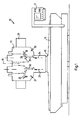
- a machine tool designated overall by 10 in FIGS. 1 and 2, has a headstock 12 which is height-displaceable via a main threaded spindle 13 (FIG. 2) which is arranged on the rear side of the headstock 12.
- the main threaded spindle 13 is accommodated in a support block 11 which is provided on the rear side with a support threaded spindle 14 for reasons of stability.
- the headstock 12 rests on a base 15 which is displaceable in the horizontal (X, Y axis) in a machine bed 16.
- the machine tool 10 is also equipped with a control panel 17, via which the functions of the machine tool can be controlled.
- the machine tool is provided with a housing, not shown here, for the purpose of machining Retain machining chips or the drilling fluid used before spraying around.
- the headstock 12 is surrounded in its upper end area by a tool magazine 20 which extends laterally and over the rear side of the headstock 12 or the support block 11.
- the detailed design of the tool magazine 20 will be described later in connection with FIG. 13.
- the headstock 12 is provided on its front or end face with a first spindle 21 and with a second spindle 22 for receiving tool holders.
- a first spindle axis 23 of the first spindle 21 and a second spindle axis 24 of the second spindle 22 (see FIG. 2) run in the vertical direction and at a distance from one another, the axis 18 of the main threaded spindle 13 being seen in a front view (FIG. 2), lies between the spindle axes 23 and 24.
- a plane perpendicular to the plane of FIG. 1 and extending through the axis 18 separates the headstock 12 into two mirror-symmetrical headstock halves.
- the headstock 12 is provided with two gripper arms 25 and 26 which form a first pair of gripper arms 27.
- the headstock 12 is provided with a gripper arm 28 and with a gripper arm 29, which form a second pair of gripper arms 30.
- the gripper arm pairs 27, 30 are articulated on both sides of the respectively associated spindle axis 23, 24.
- the gripper arms 25, 26 and 28, 29 of each pair of gripper arms 27 and 30 are designed differently and also have a different movement sequence, which is asymmetrical to the respective spindle axis 23, 24.
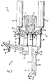
- FIG. 3 the first pair of gripper arms 27, which is arranged in Fig. 1 on the left half of the headstock 12, is shown enlarged. For reasons of clarity, only the functional parts described below are shown in connection with the movement of the first pair of gripper arms 27.
- the position of the gripping arms 25 and 26 shown in FIG. 3 corresponds to the illustration or the position as shown in FIG. 1 on the left half.
- the control and pivoting mechanism of the gripping arms 25 and 26 is described in more detail below.
- the structural design and the sequence of movements of the first pair of gripping arms 27 formed by the gripping arms 25/26 are also realized with the second pair of gripping arms 30 in a folding symmetry with respect to the parting plane running through the axis 18. This means that the following detailed description in connection with the first pair of gripper arms 27 also applies accordingly to the second pair of gripper arms 30.
- the first gripper arm 25 has a first rod 31 and a second rod 32, which are each articulated on a pivotable member 33, in the form of a plate 34 or a plate-shaped body.
- the rods 31 and 32 can be pivoted about axes which are perpendicular to the plate 34 and which pass through their articulation points.
- the rods 31 and 32 are hinged at their outer ends opposite the plate 34 to a rod 35 which carries a gripper 36 in which a tool holder 37 is received.
- the rods 31 and 32 are hinged to the plate 34 or the rod 35 in such a way that a parallelogram-like rod is formed.
- the gripper 36 together with the tool holder 37 accommodated therein is in the position shown in FIG. 3, in the so-called removal or loading position, which corresponds to an end position of the first pair of gripper arms 27.
- the tool holder 37 can be removed and transferred into the magazine 20 via mechanisms known per se. Subsequently, a tool holder with another tool can then be transferred from the tool magazine 20 to the gripper 36 of the first pair of gripper arms 27, i.e. the tool can be replaced.
- the upper rod 31 which is designed as a one-armed lever, is provided in the region between its outer articulated ends with an approximately 38 protruding projection, which is connected in a ball-and-socket manner with a rod 39.
- the rod 39 is connected at its opposite end to a lateral projection 41 of a link element 40 with a ball joint.
- the connection is therefore such that the rod 39 can be pivoted about an axis 42, as indicated by an arrow 44.
- the rod 39 can be pivoted about an axis 43 perpendicular to the axis 42, as is indicated by an arrow 45.
- the rod 39 can thus follow a circular path of its lower articulation point in the drawing plane with the attachment 38 and can also follow pivoting movements of the first pair of gripper arms 27 out of the drawing plane, for example towards the viewer.
- the lateral projection 41 of the link element 40 is connected on its upper side, which lies opposite the articulation point with the rod 39, to the outer end of a piston rod 46 of a piston-cylinder unit 47.
- the piston-cylinder unit 47 is rigidly connected to a sleeve arranged on the headstock 12.
- the longitudinal axis of the piston-cylinder unit 47 runs parallel to the vertical axis 18 or the vertical axis 23 of the first spindle 21.
- the second gripper arm 26 of the first pair of gripper arms 27 contains a rod 51 which is designed as a two-armed lever.
- the rod 51 is articulated in its lever axis with a pivotable member 53 of the headstock 12, which, as previously described in connection with the member 33, is designed as a plate 54 or plate-shaped body.
- the plate 54 is arranged at the same height as the plate 34, and the plate planes of both plates 54 and 34 are pivoted State in one level.
- the point of articulation of the rod 51 designed as a two-armed lever on the plate 54 is at the same height as the point of articulation of the rod 32 on the plate 34.
- the gripping arm 26 also has a rod 52, which is likewise pivotably connected to the plate 54 about an axis running perpendicular to the plane of the drawing.
- the point of articulation of the rod 52 on the plate 54 is at the same height as the point of articulation of the rod 31 of the gripper arm 27 on the plate 34.
- the rod 31 of the left gripper arm 25 is on the outside and the rod 52 of the right gripping arm 26 on the inside, in each case based on the plane of symmetry between the two gripping arms 25, 26.
- the rods 51 and 52 are articulated at their outer end opposite the plate 54 via a rod 55 which is provided with a gripper 56 which carries a tool holder 57.
- the rods 51, 52 also form a parallelogram-like linkage which ensures that if the gripping arm 26 is pivoted about its articulation points on the plate 54, the gripper 56 and the tool holder 57 accommodated therein remain in unchanged horizontal or vertical alignment.
- the gripping arm 26 is in the so-called spindle position which corresponds to an end position of the gripping arm 26.
- the longitudinal center axis of the tool holder 57 accommodated in the gripper 56 is located exactly in the first spindle axis 23 of the first spindle 21.
- the gripper 56 is provided with a rotary bearing for the tool holder 57, ie after the tool holder 57 has been inserted In the spindle head of the first spindle 21, the gripper 56 remains on the tool holder 57 during the machining process. For the non-positive connection between the tool holder 57 and the spindle head, the latter can be lowered onto the tool holder 57 from above with relative displacement to the sleeve.
- the gripper 55 Through a known cranked design of the gripper 55, the area of the spindle head, not shown here, of the first spindle 21 is freely accessible and is not impaired by the rods 51, 52, 55.
- the rod 55 facing away from the outer end of the rod 51 designed as a two-armed lever is connected to a rod 59 in a ball-and-socket manner.
- the rod 59 is similar to the one described above in connection with the rod 39, with a lateral projection 61 of the link element 40, i.e. pivotally connected about two spatial axes.
- the lateral projection 61 is arranged at the same height as the opposite projection 41 lying on a common axis 44.
- the lateral projection 61 is connected on its upper side opposite the articulation point with the rod 59 to the outer end of a piston rod 66 of a piston-cylinder unit 67.
- the piston-cylinder unit 67 is rigidly connected to a sleeve arranged on the headstock 12.
- the longitudinal axis of the piston-cylinder unit 67 extends in the vertical direction, ie it runs parallel and at a distance from the longitudinal axis of the opposite piston-cylinder unit 47.
- the piston-cylinder unit 47 is in a manner known per se with the Sleeve can be displaced relative to the headstock in the direction of the spindle axis in order to be able to insert tool holders with their standardized cone into the likewise conical receptacle of the headstock or to be able to lead it out again.
- the plate 34 to which the gripping arm 25 is articulated, is provided at the upper end with a rod 68 projecting upwards in the vertical.
- the plate 54 carrying the gripping arm 26 is provided with a rod 69 running parallel to the rod 68.
- the rods 68 and 69 are axially immovable in the headstock 12 and held there about their longitudinal axis.
- the rod 69 is provided at its upper end with an element 72, which is angled approximately at right angles from the longitudinal axis of the rod and protrudes towards the viewer of the illustration in FIG. 3 (see also in particular FIG. 4) and has a roller 73 at its outer front end is provided.
- the roller 73 is guided in a groove 75 of the link element 40.
- the projecting element 72 is firmly connected to the rod 69.
- the channel 75 is contoured in such a way that it has a curve contour which bulges to the right, as seen in the top view of FIG. 3.
- the rod 68 is also provided with a projecting element 70 which is provided with a roller 71 at the outer end.
- the roller 71 is guided in a groove 74 of the link element 40, which runs in mirror image to the groove 75 with respect to the spindle axis 23.
- FIG. 4 which corresponds to the position of the roller 73 in the illustration of FIG. 3, the roller 73 initially runs in the rectilinear section of the channel 75 when the link element 40 moves downward, without the rod 69 is pivoted.
- the two gripping arms 25 and 26 are pivoted in the opposite direction when viewed in the direction of the longitudinal axes of the rods 68 and 69.
- the gripping arms 25 and 26 are simultaneously moved in the opposite direction about their articulation points via the rods 39 and 59 Plates 34 and 54 pivoted.
- the link element 40 is moved downward from the position shown in FIG. 3, the gripping arm 25 is pivoted counterclockwise, whereas the gripping arm 26 is pivoted clockwise. It follows that the tool holders 37 and 57 move towards each other.
- the pivoting movement of the gripping arm 25 is set up in such a way that the tool holder 37 is transferred exactly from the end position shown in FIG. 3, the so-called removal or loading position, to the spindle position, which is shown in FIG. 3 of the tool holder 57 Has.
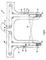
- the tool holder 57 should be brought out of the spindle position by pivoting the gripping arm 26 exactly into the position which the tool holder 37 has in the position shown in FIG. 3. This end position, in which the positions of the tool holders 37 and 57 are reversed, is shown in FIG. 6.
- FIG. 7 corresponds to the illustration in FIG. 3, FIG. 8 showing a top view of the first pair of gripper arms 27.
- FIG. 11 corresponds to the illustration in FIG. 6, FIG. 12 likewise showing a top view.
- Fig. 9 corresponds to a transition position in which the link element 40 has been shifted downwards from the position shown in Fig. 3 so that the rollers 71 and 73 are in their maximum deflected position, i.e. at a point in the link element 40 at which the channels are at the greatest distance from one another in the transverse direction.
- the plates 34 and 54 run in one plane.
- the gripper 35 holds the tool holder 37 in such a way that the tool is approximately at the level of the plate 34.
- the gripper 55 holds the tool holder 57 in such a way that it is received in the spindle head and works at a lower position.
- the arms 25 and 26 are pivoted in opposite directions by the rods 39 and 59, the tool holders 37 and 57 moving towards one another.
- the plates 34 and 54 are each pivoted in opposite directions about vertical axes via the rods 68, 69.
- the degree of pivoting has its maximum in the area in which the tool holders 36 and 56 are located at the same height, ie in the area in which they have to be moved past one another.
- the pivoting of the plates 34 and 54 ensures that the grippers 35 and 55 can move past one another in the vertical direction.
- the tool holder 37 has passed through a curved local line which runs obliquely from top to bottom and rises away from the headstock 12.
- the tool holder 57 has passed through a local curve which is directed from the bottom to the top and is curved in the direction of the headstock 12.
- the course of the channels 74 and 75 shown in FIGS. 3 and 6 can be adapted depending on the design of the grippers 35 and 55 or, in order not to produce jerky pivoting movements, can also be designed as a smooth curve.
- the second pair of gripper arms 30 is arranged in FIG. 1 in a position which corresponds to the extended position of the piston-cylinder units, as shown in FIG. 6.
- the pairs of gripper arms 27 and 30 shown in FIG. 1 can of course also be switched so that the corresponding piston-cylinder units work in the same direction.
- a T-shaped endless track 81 and 82 is provided for supplying the two pairs of gripper arms 27 and 30 with tool holders, which are accommodated in a common magazine housing 80 of the magazine 20.
- the vertical part of the T of the endless track 81 extends, as shown in FIGS. 1 and 2, to the left of the headstock 12, where the corresponding part of the endless track 82 extends to the right of the headstock 12.
- the transverse sections of the T's are arranged on the rear side of the headstock 12 and run in a line.
- the two endless tracks 81 and 82 run in a plane that is perpendicular to the main spindle axis 18.
- the endless web 81 is provided on its outer circumference with numerous grippers 83, only one being shown in FIG. 13, each of which serves to receive a tool holder 84.
- the endless belt 82 is provided with grippers 93 for receiving tool holders 94.
- a removal and loading station 86 and 87 At the front, front end of the vertical T-sections of the endless webs 81 and 82 there is a removal and loading station 86 and 87, respectively arranged.
- the removal or loading station 86 serves to supply the first pair of gripper arms 27, whereas the removal or loading station 87 serves to supply the second pair of gripper arms 30.
- a deflection roller 89 configured as a drive roller, of the first endless track 81 is connected to the corresponding deflection roller 90 of the endless track 82, which is arranged in mirror image, via a simply crossed belt element 88. If the roller 89 is therefore moved counterclockwise, the tool 84 located on the left outer side of the endless path 81 is moved toward the removal or loading position 86. Due to the simply crossed guide to the roller 90, a mirror 94 arranged on the right side of the endless web 82 is likewise moved in the same direction and by the same distance to the removal or loading station 87. Thus, if the two T-shaped endless tracks 81 and 82 are loaded mirror-symmetrically, both removal and loading stations 86 and 87 can be supplied synchronously with the same tool by means of the coupling by means of a single drive.
- both pairs of gripper arms 27 and 30 also transfer the same tool holder from the magazine to the spindle position or transport it away, i.e. two identical workpieces can be machined simultaneously with two identical tools.
- the machining capacity is thus doubled compared to a single-spindle version.
- the opposing drive of the endless tracks 81 and 82 also enables the grippers 83 and 93 to be loaded more easily. If a centrally arranged plate 96 on the rear of the housing 80 is opened, positions 97 and 98 of the endless tracks 81 and 82 are accessible, where there are the same tool holders. These can therefore be fitted or removed in pairs, which helps to avoid errors.
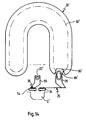
- FIG. 14 shows a schematic plan view of another embodiment of a machine tool according to the invention, in which the tool magazine 20 'is designed in the manner of a horseshoe.
- a "horseshoe magazine” is known and described in detail, for example, in DE-PS 35 21 009 by the applicant.
- the disclosure content of that document is also made the disclosure content of the present application by this reference.
- the horseshoe magazine 20 ' is provided with a likewise horseshoe-shaped endless track 82' from which tool holder 83 'can be removed or equipped at a removal or loading position 86'.
- the horseshoe magazine 20 ' has only one such position 86'.
- the pair of gripper arms with gripper arms 25, 26 is provided in the manner already described, the gripper arm pair being arranged on the headstock 12 'of the machine tool.
- the spindle axis 23 ' is preferably in the longitudinal median plane of the horseshoe magazine 20'.
Description
Die Erfindung betrifft eine Werkzeugmaschine mit einem Spindelstock, mit einem Werkzeugmagazin in dem eine Mehrzahl von mit Werkzeughaltern bestückten Greifern entlang einer Endlosbahn verfahrbar ist, und mit zwei Greifarmen zum Transportieren der Werkzeughalter Zwischen einer gemeinsamen Entnahme- bzw. Bestückungsposition am Werkzeugmagazin und einer Spindelposition an einem Spindelkopf des Spindelstockes, wobei die Greifarme beidseitig einer Achse des Spindelstockes auf gegenüberliegenden Seiten neben dem Spindelstock angelenkt und gleichzeitig und gegenläufig zwischen ihrer Spindelposition und ihrer Entnahme- bzw. Bestückungsposition verschwenkbar sind.The invention relates to a machine tool with a headstock, with a tool magazine in which a plurality of grippers equipped with tool holders can be moved along an endless path, and with two gripping arms for transporting the tool holder between a common removal or loading position on the tool magazine and a spindle position at one Spindle head of the headstock, the gripping arms articulated on both sides of an axis of the headstock on opposite sides next to the headstock and can be pivoted simultaneously and in opposite directions between their spindle position and their removal or loading position.
Aus der DE-PS 20 13 836 sowie der DE-AS 15 52 324 sind Werkzeugmaschinen mit Werkzeugwechseleinrichtungen bekannt, bei denen ein Greifarmpaar vorgesehen ist, um Werkzeughalter zwischen einem Werkzeugmagazin und einer Aufnahme des Spindelstockes durch alternative Betätigung hin- und herzutransportieren. Die Anordnung ist dabei so getroffen, daß beide Greifarme des Greifarmpaares mit derselben Bestückungs-/Entnahmeposition des Werkzeugmagazins zusammenarbeiten. Allerdings sind beide Greifarme identisch bzw. klappsymmetrisch ausgebildet und ihr Bewegungsablauf ist ebenfalls gegenläufig symmetrisch und zwar zur Spindelachse bzw. einem Punkt auf der Achse.From DE-PS 20 13 836 and DE-AS 15 52 324, machine tools with tool changing devices are known, in which a pair of gripper arms is provided to transport tool holders between a tool magazine and a receptacle of the headstock by alternative actuation to and fro. The arrangement is such that both gripper arms of the pair of gripper arms work together with the same loading / unloading position of the tool magazine. However, both gripping arms are identical or have a folding symmetry and their movement sequence is also symmetrical in opposite directions, specifically to the spindle axis or a point on the axis.
Diese beiden bekannten Werkzeugmaschinen haben daher den Nachteil, daß aufgrund des symmetrischen Bewegungsablaufes beider seitlich von der Spindelachse angeordneter Greifarme jedes Greifarmpaares zu beiden Seiten der Spindelachse ein erheblicher Freiraum vorhanden sein muß, um die Bewegung der Greifarme zu ermöglichen.These two known machine tools therefore have the disadvantage that, due to the symmetrical movement sequence of both gripper arms arranged laterally from the spindle axis, each gripper arm pair must have considerable free space on both sides of the spindle axis in order to enable the movement of the gripper arms.
Bei einer weiteren, aus der DE-PS 35 21 009 bekannten Werkzeugmaschine weist das Magazin die Form eines U bzw. Hufeisens auf und die Entnahme- bzw. Bestückungsposition befindet sich an beiden Enden der Schenkel des U. Der Spindelkopf ist vor und unterhalb dieser Enden angeordnet. Die Greifarme arbeiten auf gegenüberliegenden Seiten des Spindelstockes und zwar derart, daß, falls sich der eine Arm mit seinem Werkzeughalter in der tiefer gelegenen Spindelposition befindet, der andere Arm derart seitlich verschwenkt ist, daß dessen Werkzeughalter sich in der Entnahme-bzw. Bestückungsposition an einem Ende des Hufeisenmagazins befindet. Bei einem Werkzeugwechsel wird der eine Arm, dessen Werkzeughalter an einem Ende des Hufeisenmagazins ein Werkzeug aufgenommen hat, in Richtung Spindelposition auf den Spindelstock zu bewegt. Gleichzeitig bewegt sich der andere Arm, dessen Werkzeughalter sich in der Spindelposition befunden hat, in gegensinniger Richtung wie der eine Arm vom Spindelkopf weg in Richtung auf das andere, gegenüberliegende Ende des Hufeisenmagazins, um dort das vom Spindelkopf abgenommene Werkzeug an das Magazin zu übergeben. Mit der bekannten Werkzeugmaschine ist ein Werkzeugwechsel zwar sehr rasch durchzuführen, allerdings baut eine derartige Maschine beidseitig des Spindelstockes sehr breit, da links und rechts vom Spindelstock genügend Raum für die Schwenkbewegung eines jeden Armes zur Verfügung stehen muß.In a further machine tool known from DE-PS 35 21 009, the magazine has the shape of a U or horseshoe and the removal or loading position is at both ends of the legs of the U. The spindle head is in front of and below these ends arranged. The gripper arms work on opposite sides of the headstock in such a way that if one arm with its tool holder is in the lower spindle position, the other arm is pivoted laterally in such a way that its tool holder themselves in the removal or. Placement position at one end of the horseshoe magazine. When changing tools, one arm, the tool holder of which has received a tool at one end of the horseshoe magazine, is moved towards the spindle position in the direction of the spindle position. At the same time, the other arm, whose tool holder was in the spindle position, moves in the opposite direction as one arm away from the spindle head towards the other, opposite end of the horseshoe magazine, in order to transfer the tool removed from the spindle head to the magazine. With the known machine tool, a tool change can be carried out very quickly, but such a machine builds very wide on both sides of the headstock, since there must be enough space left and right of the headstock for the pivoting movement of each arm.
Es ist oftmals wünschenswert, insbesondere für Großserienfertigungen, bei einer Werkzeugmaschine mehrere nebeneinander angeordnete Spindelstöcke auf möglichst geringem Raum unterzubringen. Bei einer Maschine nach Art der eingangs genannten Maschine müßte dann der Mindestabstand zwischen zwei Spindelköpfen das doppelte der maximalen seitlichen Schwenkbreite eines Schwenkarmes betragen. Daraus würde sich beispielsweise bei einer Doppelspindelmaschine eine sehr breit bauende Maschine ergeben. Es ist ferner bei Doppelspindelstöcken wünschenswert, lediglich einen Antrieb für beide Spindelköpfe vorzusehen. Sind diese jedoch weit voneinander beabstandet, so können durch die langen Kraftübertragungswege Vibrationen und Unruhen entstehen, so daß sehr massive und somit schwergewichtige Werkzeugmaschinen hergestellt werden müßten, um dem entgegenzuwirken. Eine solche Werkzeugmaschine würde daher nicht nur sehr breit bauen, sondern wäre auch übermäßig schwer.It is often desirable, particularly for large series production, to accommodate a plurality of headstocks arranged next to one another in the smallest possible space in a machine tool. In a machine of the type mentioned above, the minimum distance between two spindle heads would then have to be twice the maximum lateral swivel width of a swivel arm. In a double-spindle machine, for example, this would result in a very broad machine. It is also desirable in the case of double headstocks to provide only one drive for both spindle heads. However, if these are spaced far apart, vibrations and unrest can occur due to the long power transmission paths arise, so that very massive and thus heavy weight machine tools would have to be manufactured to counteract this. Such a machine tool would not only be very wide, but would also be excessively heavy.
Aufgabe der vorliegenden Erfindung ist daher, eine Werkzeugmaschine der eingangs genannten Art derart weiterzubilden, daß unter Beibehaltung minimaler Werkzeugwechselzeiten ein geringerer Platzbedarf in seitlicher Richtung für die den Wechselvorgang durchführenden Bauteile notwendig ist. Darunter ist auch zu verstehen, daß eine Werkzeugmaschine mit einem Doppelspindelstock mit geringem Abstand der Spindelachsen geschaffen werden kann.The object of the present invention is therefore to further develop a machine tool of the type mentioned at the outset such that, while maintaining minimal tool changing times, less space is required in the lateral direction for the components which carry out the changing process. This also means that a machine tool with a double headstock can be created with a small distance between the spindle axes.
Erfindungsgemäß wird die Aufgabe dadurch gelöst, daß die Greifarme, einander überkreuzend, entlang von nur auf einer Seite des Spindelstockes verlaufenden Ortskurven zu der gemeinsamen Entnahme-bzw. Bestückungsposition verschwenkbar sind, die sich asymmetrisch zur Achse auf der einen Seite des Spindelstockes befindet.According to the invention the object is achieved in that the gripping arms, crossing one another, along local curves running only on one side of the headstock to the common removal or. Assembly position are pivotable, which is asymmetrical to the axis on one side of the headstock.
Diese Maßnahmen haben den Vorteil, daß sich beide Schwenkarme lediglich zwischen der Spindelposition und ein und der selben Entnahme- bzw. Bestückungsposition bewegen. Das heißt, bewegt sich ein Arm mit seinem Werkzeughalter vom Spindelkopf in seitlicher Richtung auf das Magazin hin zu, bewegt sich gleichzeitig in entgegengesetzter Richtung der andere Arm vom Magazin zum Spindelkopf. Durch Vorsehen von ausweichenden Ortskurven die an den Endpunkten zusammentreffen, können die Arme aneinander vorbeibewegt werden, ohne daß sie sich bzw. die von ihnen gehaltenen Werkzeughalter samt den darin befindlichen Werkzeugen treffen. Daraus folgt, daß der Raumbedarf für die verschwenkenden Arme, in der Breite gesehen, nur noch halb so groß ist wie bei den eingangs erwähnten Werkzeugmaschinen. Die Transportbewegung findet, von der Spindelstockachse aus gesehen, nur auf einer Seite des Spindelstockes bzw. der Spindelachse statt. Die Maßnahme hat ferner den Vorteil, daß der Spindelstock auf einer Seite frei zugänglich ist, d.h. nicht durch das Magazin oder die verschwenkten Arme versperrt ist. Dadurch ist es beispielsweise möglich, Wartungs- und Reparaturarbeiten leichter durchzuführen. Ferner hat die Maßnahme den Vorteil, falls der Spindelstock in Querrichtung verfahrbar ist, daß dieser in der seitlichen Verfahrrichtung, die den Schwenkarmen gegenüberliegt, bis unmittelbar an ein ggf. vorhandenes Maschinengehäuse herangefahren werden kann. Dadurch können beispielsweise bei an sich gleichen Außenmaßen von Werkzeugmaschinen größere Werkstücke bearbeitet werden.These measures have the advantage that both swivel arms only move between the spindle position and one and the same removal or loading position. This means that if one arm moves with its tool holder from the spindle head in a lateral direction towards the magazine, the other arm simultaneously moves in the opposite direction from the magazine to the spindle head. By providing evasive locus curves that meet at the end points, the arms can be moved past each other without them or hit the tool holder they hold together with the tools inside. It follows that the space required for the pivoting arms, viewed in width, is only half as large as in the machine tools mentioned at the beginning. The transport movement, seen from the headstock axis, only takes place on one side of the headstock or the spindle axis. The measure also has the advantage that the headstock is freely accessible on one side, ie is not blocked by the magazine or the pivoted arms. This makes it easier, for example, to carry out maintenance and repair work. Furthermore, the measure has the advantage, if the headstock can be moved in the transverse direction, that it can be moved up to a possibly existing machine housing in the lateral direction of travel, which lies opposite the swivel arms. This allows larger workpieces to be machined, for example, with the same overall dimensions of machine tools.
Bei einer weiteren Ausgestaltung der Erfindung ist der Spindelstock als Doppelspindelstock mit zwei Spindeln ausgebildet, wobei jede der Spindeln mit einem Paar von zwei Greifarmen versehen ist und die gemeinsame Entnahme- bzw. Bestückungsposition jedes Paares sich jeweils auf der von der jeweils anderen Spindel abgewandten Seite der Spindel befindet.In a further embodiment of the invention, the headstock is designed as a double headstock with two spindles, each of the spindles being provided with a pair of two gripping arms and the common removal or loading position of each pair being on the side of the spindle facing away from the other Spindle is located.
Diese Maßnahme hat den Vorteil, daß ein Doppelspindelstock realisiert werden kann, der nur eine minimale seitliche Ausdehnung aufweist.This measure has the advantage that a double headstock can be realized that has only a minimal lateral expansion.
Bei einer vorteilhaften Ausgestaltung der Erfindung ist jeder Greifarm maschinenseitig an einem Organ des Spindelstockes zwischen den Endpositionen hin- und herschwenkbar angelenkt, und jedes Organ des Spindelstockes ist um eine weitere Achse derart schwenkbar, daß die gegenläufig verschwenkbaren Arme berührungsfrei aneinander vorbeiführbar sind.In an advantageous embodiment of the invention, each gripper arm is on the machine side on an organ of the headstock hinged to and fro between the end positions, and each organ of the headstock can be pivoted about a further axis in such a way that the arms which can be pivoted in opposite directions can be moved past one another without contact.
Diese Maßnahme hat den Vorteil, daß auf konstruktiv einfache Art und Weise die Greifarme ihre Verschwenkbewegung zwischen den Endpositionen durchführen können und gleichzeitig während des Verschwenkens in einer weiteren Raumrichtung verschwenkt werden können, um sich bei diesen Schwenkbewegungen nicht zu berühren. Durch die Überlagerung der Schwenkbewegung des Organes des Spindelstockes um die weitere Achse mit der Verschwenkbewegung der an dem Organ angelenkten Greifarme, kann auf einfache Weise eine gewünschte Ortskurve erzeugt werden, die an die Ausmaße der Werkzeughalter bzw. dem darin aufgenommenen Werkzeug einfach anpaßbar ist.This measure has the advantage that the gripping arms can carry out their pivoting movement between the end positions in a structurally simple manner and at the same time can be pivoted in a further spatial direction during pivoting so as not to touch one another during these pivoting movements. By superimposing the pivoting movement of the headstock organ about the further axis with the pivoting movement of the gripping arms articulated on the organ, a desired locus curve can be generated in a simple manner, which is easily adaptable to the dimensions of the tool holder or the tool accommodated therein.
Bei einer bevorzugten Ausgestaltung der Erfindung ist jeder Greifarm um eine etwa senkrecht zur vertikalen Spindelachse verlaufenden Achse schwenkbar an einem Organ des Spindelstockes angelenkt, und die weitere Achse verläuft vertikal.In a preferred embodiment of the invention, each gripping arm is pivotably articulated on an organ of the headstock about an axis running approximately perpendicular to the vertical spindle axis, and the further axis runs vertically.
Diese Maßnahme hat den Vorteil, daß die Schwenkarme weiterhin eine im wesentlichen vor der Stirnfläche des Spindelstocks ablaufende Bewegung zwischen den Endpositionen durchführen können. Durch die Verschwenkbarkeit des schwenkbaren Organs um eine vertikale Achse, ist es möglich, durch bauliche einfache Maßnahmen, die zusätzliche Verschwenkbarkeit vom Spindelstock aus zu steuern, ohne daß raumergreifende, möglicherweise die Schwenkbewegung behindernde oder beeinträchtigenden Maßnahmen notwendig sind. Durch Einbetten der vertikal verlaufenden Schwenkachsen der verschwenkbaren Organe in den Spindelstock, kann eine stabile und präzise Führung der verschwenkenden Arme trotz Vorsehen einer zusätzlichen Verschwenkmöglichkeit sichergestellt werden.This measure has the advantage that the swivel arms can continue to carry out a movement between the end positions essentially in front of the end face of the headstock. Due to the pivotability of the pivotable member about a vertical axis, it is possible to control the additional pivotability from the headstock by means of simple structural measures, without the need for bulky, possibly obstructing or impairing the pivoting movement. By embedding the vertical ones Swiveling axes of the swiveling organs in the headstock, stable and precise guidance of the swiveling arms can be ensured despite the provision of an additional swiveling possibility.
In einer weiteren bevorzugten Ausgestaltung der Erfindung dient ein Betätigungsorgan zum Verschwenken der Arme auch zur Betätigung des verschwenkbaren Organes.In a further preferred embodiment of the invention, an actuating member for pivoting the arms also serves to actuate the pivotable member.
Diese Maßnahme hat den Vorteil, daß durch besonders einfache bauliche Maßnahmen beide Verschwenkbewegungen von ein und demselben Organ durchgeführt werden können. Daraus folgt trotz der Notwendigkeit einer zweiten Verschwenkmöglichkeit eine baulich wenig aufwendige Konstruktion.This measure has the advantage that both pivoting movements can be carried out by one and the same organ through particularly simple structural measures. Despite the necessity of a second pivoting possibility, this results in a structurally less complex construction.
In einer weiteren besonders bevorzugten Ausgestaltung der Erfindung ist das Betätigungsorgan mit einem Kulissenelement verbunden, das durch das Betätigungsorgan längs einer vertikalen Achse am Spindelstock auf- und abbewegbar ist, ferner ist das Kulissenelement über ein in einer Rinne des Kulissenelements laufendes Element mit einem verschwenkbaren Organ derart verbunden, daß ein Auf- und Abbewegen des Kulissenelements die verschwenkbaren Organe jeweils gegensinnig aus einer Ruhelage bis zu einem Maximum und dann wieder in die Ruhelage verschwenkt.In a further particularly preferred embodiment of the invention, the actuating member is connected to a link element which can be moved up and down along the vertical axis on the headstock by the actuating member, furthermore the link element is of such a type with a pivotable member running in a groove of the link element connected that an up and down movement of the link element in each case in opposite directions from a rest position to a maximum and then pivoted back to the rest position.
Diese Maßnahme hat den Vorteil, daß durch die Kulissenführung eine exakte Steuerung der Verschwenkbewegung des verschwenkbaren Organes durchgeführt werden kann. Durch die gegensinnige Verschwenkung der verschwenkbaren Organe müssen diese nur um einen relativ geringen Winkel verschwenkt werden, um am Ende der mit den Werkzeughaltern versehenen Greifarmen für einen solchen Abstand zu sorgen, daß diese Ende sich aneinander vorbeibewegen können. Ferner ist dabei sichergestellt, daß in den Endpositionen jedoch beide Werkzeughalter jeweils exakt die Position einnehmen, die der zuvor von dieser Position wegbewegte Greifarm bzw. dessen Werkzeughalter inne hatte.This measure has the advantage that precise control of the pivoting movement of the pivotable member can be carried out by the link guide. Due to the opposite pivoting of the pivotable organs, they only have to be pivoted by a relatively small angle in order to provide such a distance at the end of the gripping arms provided with the tool holders that these ends are in contact with one another can move past. This also ensures that, in the end positions, however, both tool holders each occupy exactly the position that the gripping arm or its tool holder previously moved from this position had.
In einer besonders bevorzugten Ausgestaltung der Erfindung sind die Rinnen derart konturiert, daß das Maximum der Verschwenkbewegung des verschwenkbaren Organes der Stellung entspricht, in der sich die Werkzeughalter der gegenläufig arbeitenden Arme kreuzen.In a particularly preferred embodiment of the invention, the channels are contoured such that the maximum of the pivoting movement of the pivotable member corresponds to the position in which the tool holders of the arms working in opposite directions cross.
Diese Maßnahme hat den Vorteil, daß an der Stelle, an der sich die relativ weit ausladenden Werkzeughalter begegnen bzw. aneinander vorbeigleiten, der notwendige Maximalabstand zwischen den Armen geschaffen ist. Dadurch ist es möglich, beispielsweise bereits auf dem Markt gebräuchliche relativ weit ausladende Greifer zu verwenden. Die Werkzeuge führen dabei zwischen den Endpositionen entgegengesetzt gerichtet gekrümmte Ortskurven durch, deren maximaler Abstand exakt an der Begegnungsstelle vorliegt. Die Begegnungsstelle liegt etwa in der Mitte zwischen Spindelposition und Werkzeugmagazin (bzw. Entnahme- bzw. Bestückungsposition), d.h. an einer Stelle, die weder vom Spindelstock noch vom Magazin belegt wird, so daß für die Begegnung bzw. das Aneinandervorbeibewegen der beiden Greifer der Greifarme genügend Raum zur Verfügung steht, ohne daß besondere Raumvorkehrungen am Spindelstock oder am Magazin getroffen werden müssen.This measure has the advantage that the necessary maximum distance between the arms is created at the point at which the relatively widely protruding tool holders meet or slide past one another. This makes it possible, for example, to use grippers which are relatively wide and which are already in use on the market. The tools perform curved curves in opposite directions between the end positions, the maximum distance of which is exactly at the meeting point. The meeting point lies approximately in the middle between the spindle position and the tool magazine (or removal or loading position), i.e. at a point that is neither occupied by the headstock nor by the magazine, so that enough space is available for the meeting or moving the two grippers of the gripping arms without having to take special space precautions on the headstock or on the magazine.
In einer weiteren besonders bevorzugten Ausgestaltung der Erfindung ist das verschwenkbare Organ als plattenförmiger Körper ausgebildet, an dessen Außenseite ein Arm angelenkt ist, und vom Körper erstreckt sich eine Stange weg, die am äußeren Ende mit einem vorspringenden Element versehen ist, das in der Rinne des Kulissenelements läuft und dabei die Stange um ihre Längsachse verschwenkt. Diese Maßnahme hat den Vorteil, daß durch baulich einfache Maßnahmen die Verschwenkbewegung für das Ausweichen der Arme gesteuert werden kann, wobei eine exakte Führung gewährleistet ist. Ferner können diese Bauteile einfach ausgewechselt werden, d.h. an ggf. sich ändernde Werkzeuggrößen bzw. -breiten und damit ändernde Seitenabstände beim Aneinandervorbeigleiten der Arme angepaßt werden.In a further particularly preferred embodiment of the invention, the pivotable member is designed as a plate-shaped body, on the outside of which an arm is articulated and a rod extends away from the body, which is provided at the outer end with a projecting element which runs in the groove of the link element and thereby pivots the rod about its longitudinal axis. This measure has the advantage that the pivoting movement for evading the arms can be controlled by structurally simple measures, with an exact guidance being ensured. Furthermore, these components can be easily replaced, ie they can be adapted to changing tool sizes or widths and thus changing side distances when the arms slide past each other.
In einer Weiteren Ausgestaltung der Erfindung ist die Stange im Bereich zwischen plattenförmigem Körper und vorspringendem Element im Spindelstock axial fest, jedoch um ihre Längsachse verschwenkbar gehalten.In a further embodiment of the invention, the rod is axially fixed in the area between the plate-shaped body and the projecting element in the headstock, but is pivotable about its longitudinal axis.
Diese Maßnahme hat den Vorteil, daß eine extrem feste Halterung und gute Führung im massiven Spindelstock möglich ist, so daß auch bei schwerstem Werkzeug mit ggf. Weit ausladenden Greifarmen eine feste Halterung der die Greifarme tragenden plattenartigen Körper gewährleistet ist.This measure has the advantage that an extremely firm mounting and good guidance in the solid headstock is possible, so that even with the heaviest tool with possibly wide-reaching gripping arms a firm mounting of the plate-like body carrying the gripping arms is ensured.
In einer weiteren Ausgestaltung der Erfindung ist das Kulissenelement über je einen beidseitig angelenkten Stab mit je einem Arm derart verbunden, daß eine Bewegung des Kulissenelements in einer Richtung zwischen zwei vertikalen Endpunkten das gegenläufige Verschwenken der Arme zwischen deren Endpositionen verursacht, und daß der Stab dabei der Verschwenkbewegung des verschwenkbaren Organes folgt.In a further embodiment of the invention, the link element is connected to an arm by means of a rod articulated on both sides in such a way that movement of the link element in one direction between two vertical end points causes the arms to pivot in opposite directions between their end positions, and that the rod thereby moves Pivotal movement of the pivotable organ follows.
Diese Maßnahme hat den Vorteil, daß das Kulissenelement einerseits die Verschwenkung der Arme zwischen den Endpositionen über die Stäbe steuert und gleichzeitig durch die in den Rinnen des Kulissenelements laufenden vorspringenden Elemente der Stangen die Schwenkbewegung für das Aneinandervorbeigleiten steuert. Jeder Stab ist dabei an dem Kulissenelement in zwei Raumrichtungen schwenkbar angelenkt, so daß er den Schwenkbewegungen des Armes in allen Schwenkrichtungen folgen kann.This measure has the advantage that the link element on the one hand controls the pivoting of the arms between the end positions via the rods and, at the same time, controls the pivoting movement for sliding past one another by the projecting elements of the rods running in the grooves of the link element. Each rod is pivotally connected to the link element in two spatial directions so that it can follow the pivoting movements of the arm in all pivoting directions.
In einer weiteren Ausgestaltung der Erfindung ist der eine Stab mit einem ersten Arm, der als einarmiger Hebel ausgebildet ist, zwischen dessen Hebelachse und dessen äußeren, einen Greifer tragenden Ende gelenkig verbunden, und der andere Stab ist mit einem äußeren Ende eines zweiten Armes, der als zweiarmiger Hebel ausgebildet ist, gelenkig verbunden, wobei der zweite Arm an seinem anderen äußeren Ende mit einem Greifer versehen ist.In a further embodiment of the invention, the one rod with a first arm, which is designed as a one-armed lever, is articulated between the lever axis and the outer end thereof, which carries a gripper, and the other rod is connected to an outer end of a second arm, the is designed as a two-armed lever, hingedly connected, the second arm being provided with a gripper at its other outer end.
Diese Maßnahme hat den Vorteil, daß beispielsweise eine nach unten gerichtete Bewegung des Kulissenelements dafür sorgt, daß der erste Arm nach unten verschwenkbar, wohingegen der zweite Arm nach oben verschwenkbar ist. Es wird somit auf eine konstruktiv besonders einfache und stabile Weise durch ein in einer Richtung bewegendes Steuerorgan, d.h. die Bewegung des Kulissenelements, die gegenläufige Bewegung der beiden Arme hervorgerufen.This measure has the advantage that, for example, a downward movement of the link element ensures that the first arm can be pivoted downwards, whereas the second arm can be pivoted upwards. It is thus carried out in a structurally particularly simple and stable manner by a control element moving in one direction, i.e. the movement of the link element, the opposite movement of the two arms.
In einer weiteren Ausgestaltung der Erfindung ist jeder Arm mit einer Parallelogrammführung versehen. Diese an sich bekannte Maßnahme sorgt dafür, daß der Werkzeughalter samt dem Werkzeug in jeder Schwenkstellung seine vertikale Ausrichtung behält.In a further embodiment of the invention, each arm is provided with a parallelogram guide. This measure, which is known per se, ensures that the tool holder, together with the tool, maintains its vertical orientation in every pivoting position.
In einer weiteren vorteilhaften Ausgestaltung der Erfindung ist das Betätigungsorgan als in vertikaler Richtung arbeitende Kolben-Zylinder-Einheit ausgebildet, deren äußeres Kolbenstangenende mit dem Kulissenelement verbunden ist. Diese konstruktiv besonders einfache, stabile und somit sichere und exakt führende Ausgestaltung stellt sicher, daß durch das Betätigungsorgan über das Kulissenelement der notwendige Kraftfluß zu den Greifarmen hergestellt wird.In a further advantageous embodiment of the invention, the actuating member is designed as a piston-cylinder unit working in the vertical direction, the outer piston rod end of which is connected to the link element. This structurally particularly simple, stable and thus safe and precisely guiding design ensures that the necessary force flow to the gripping arms is produced by the actuating member via the link element.
In einer weiteren Ausgestaltung der Erfindung weist das Betätigungsorgan zwei symmetrisch zur Spindelachse angeordnete Kolben-Zylinder-Einheiten auf, zwischen denen das Kulissenelement und darunter gelegen die jeweils verschwenkbaren Organe angeordnet sind, und daß die im Kulissenelement aufgenommenen Stangen ebenfalls symmetrisch zur Spindelachse verlaufen.In a further embodiment of the invention, the actuating member has two piston-cylinder units arranged symmetrically to the spindle axis, between which the link element and, below it, the respective pivotable members are arranged, and that the rods received in the link element also run symmetrically to the spindle axis.
Die beidseitig angeordneten Kolben-Zylinder-Einheiten sorgen für einen verkantfreien Bewegungsablauf längs der Spindelachse. Durch die Aufnahme der Steuerelemente zwischen und unterhalb der Kolben-Zylinder-Einheiten, sind die Betätigungs- und Steuerorgane für die Schwenkbewegung äußerst günstig an der Stirnseite des Spindelstockes anordenbar, so daß der Bereich des Spindelkopfes weiterhin frei zugänglich bzw. lediglich durch die verschwenkenden Greifarme belegt wird. Die vertikale Führung der Kolben-Zylinder-Einheit sowie die vertikale Ausrichtung der Stangen, führt zu einem kompakten, steifen und verzugfreien Mechanismus, so daß ein exakter Ablauf des Werkzeugwechselvorganges auf Dauer sichergestellt ist.The piston-cylinder units arranged on both sides ensure a tilt-free movement along the spindle axis. By incorporating the control elements between and below the piston-cylinder units, the actuating and control elements for the pivoting movement can be arranged extremely cheaply on the end face of the headstock, so that the area of the spindle head is still freely accessible or only occupied by the pivoting gripper arms becomes. The vertical guidance of the piston-cylinder unit and the vertical alignment of the rods result in a compact, rigid and distortion-free mechanism, so that an exact sequence of the tool changing process is ensured in the long run.
In einer weiteren Ausgestaltung der Erfindung verläuft die Endlosbahn des Werkzeugmagazins T-förmig und die Endlosbahn ist in einer Ebene senkrecht zur Vertikalachse und höherliegend als die Spindelposition, verfahrbar, wobei sich die Entnahme-bzw. Bestückungsposition am unteren Ende des T befindet.In a further embodiment of the invention, the endless track of the tool magazine runs in a T-shape and the endless track can be moved in a plane perpendicular to the vertical axis and higher than the spindle position, the removal or. Assembly position is located at the lower end of the T.
Diese Maßnahme hat den Vorteil, daß das Magazin sich seitlich sehr nah an den Spindelstock heranschmiegen kann. Der querverlaufende Bereich der T-förmigen Endlosbahn kann dann auf der rückwärtigen Seite hinter dem Spindelstock angeordnet werden.This measure has the advantage that the magazine can nestle very close to the side of the headstock. The transverse region of the T-shaped endless track can then be arranged on the rear side behind the headstock.
In einer weiteren Ausgestaltung der Erfindung ist jeder Spindel jeweils ein Werkzeugmagazin mit T-förmiger Endlosbahn angeordnet.In a further embodiment of the invention, each spindle has a tool magazine with a T-shaped endless track.
Diese Maßnahme hat den Vorteil, daß zwei sehr benachbart angeordnete Spindeln mit wechselndem Werkzeug versorgt werden können. Die spiegelsymmetrische Anordnung der beiden Greifarmpaare ermöglicht eine relativ nahe Anordnung der beiden Spindeln, so daß die beiden Spindeln ohne größeren technischen Aufwand und ohne die Gefahr von Vibrationen aufgrund langer Kraftübertragungswege von einem einzigen Antrieb bewegt werden können. Die seitliche Ausladung dieser Doppelspindel entspricht etwa einer herkömmlichen Einfachspindel mit beidseitig gegensinnig verschwenkenden Armen, d.h. bei etwa gleicher Baubreite ist eine Verdoppelung der Arbeitsgeschwindigkeit durch Vorsehen zweier rasch versorgbarer Spindeln erreicht.This measure has the advantage that two very closely arranged spindles can be supplied with changing tools. The mirror-symmetrical arrangement of the two pairs of gripper arms enables a relatively close arrangement of the two spindles, so that the two spindles can be moved by a single drive without great technical effort and without the risk of vibrations due to long power transmission paths. The lateral projection of this double spindle corresponds approximately to a conventional single spindle with arms pivoting in opposite directions on both sides, i.e. with roughly the same width, the working speed is doubled by providing two spindles that can be quickly supplied.
In einer weiteren Ausgestaltung der Erfindung sind beide Endlosbahnen über einen einzigen Antrieb mittels eines einmal gekreuzt geführten Riemenelements synchron verfahrbar.In a further embodiment of the invention, both endless tracks can be moved synchronously by means of a single drive by means of a belt element which is once crossed.
Diese Maßnahme hat den Vorteil, daß synchron zwei identische Werkstücke durch die beiden Spindeln mit gleichartigen Werkzeugen gleichzeitig bearbeitet werden können, wobei eine spiegelbildliche Bestückung der T-förmigen Endlosbahnen dazu führt, daß eine durch einen einzigen Antrieb verursachte Bewegung des Riemenelements in beiden T-förmigen Endlosbahnen eine gleichsinnige Transportrichtung verursacht, d.h., daß in beiden Endlos-T-Bahnen zwei gleiche Werkzeuge zur Entnahme- bzw. Beschickungspositionen transportiert werden. Diese werden dann gleichzeitig von je einem Greifarm der beiden Greifarmpaare ergriffen und synchron zu jeweils einer Spindel gebracht. Dort können dann ebenfalls durch den gemeinsamen Spindelantrieb zwei gleichartige Bearbeitungsvorgänge an zwei verschiedenen Werkstücken synchron durchgeführt werden. Dadurch kann eine Verdopplung der Arbeitsleistung einer Werkzeugmaschine erreicht werden, wobei lediglich ein gemeinsamer Antrieb für beide Spindeln und ein gemeinsamer Antrieb für die beiden T-förmigen Endlosbahnen der Werkzeugmagazine vorgesehen sein muß. Ein weiterer Vorteil dieser Maßnahmen ist daß der Werkzeugwechsel vereinfacht wird, wenn vor Beginn eines neuen Produktionsvorganges das Magazin mit Werkzeughaltern bestückt bzw. nach Abschluß des Produktionsvorganges wieder entladen werden soll.This measure has the advantage that two identical workpieces can be machined simultaneously by the two spindles with similar tools, a mirror image of the T-shaped endless tracks resulting in a movement of the belt element caused by a single drive in both T-shaped ones Endless webs cause a transport direction in the same direction, ie two identical tools for removal or loading positions are transported in both endless T-webs. These are then gripped simultaneously by one gripper arm of each of the two gripper arm pairs and brought synchronously to one spindle each. There, two similar machining operations can then also be carried out synchronously on two different workpieces by the common spindle drive. As a result, the work output of a machine tool can be doubled, only one common drive for both spindles and one common drive for the two T-shaped endless tracks of the tool magazines having to be provided. Another advantage of these measures is that the tool change is simplified if the magazine is to be fitted with tool holders before the start of a new production process or is to be unloaded again after the production process has ended.
Infolge der gegenläufig angetriebenen Endlosbahnen erscheinen dann nämlich in dem Bereich, in dem die beiden horizontalen Balken der T-förmigen Endlosbahnen aneinander grenzen, immer die gleichen Werkzeughalter, die dann auch paarweise in das Magazin geladen bzw. aus diesem entladen werden können. Diese paarweise Bestückung vermindert jedoch das Risiko, beim Bestücken der Magazine Bestückungsfehler zu begehen.As a result of the oppositely driven endless tracks, the same tool holders then appear in the area in which the two horizontal bars of the T-shaped endless tracks adjoin one another, which can then also be loaded into or unloaded from the magazine in pairs. However, this paired loading reduces the risk of mounting errors when loading the magazines.
In einer weiteren Ausgestaltung der Erfindung grenzen die T-förmigen Magazine hinter dem Hauptspindelstock an gegenüberliegenden äußeren Enden der querverlaufenden Abschnitte der T's aneinander, und sind in einem durchgehenden Magazingehäusee aufgenommen.In a further embodiment of the invention, the T-shaped magazines adjoin one another behind the main headstock at opposite outer ends of the transverse sections of the T's, and are accommodated in a continuous magazine housing.
Diese Maßnahme hat den Vorteil, daß beide T-förmigen Endlosbahnen in einem einzigen Werkzeugmagazin aufgenommen werden können, das sich über die gesamte rückwärtige Seite des Hauptspindelstockes erstreckt und somit einen Raum ausfüllt, der zu diesem Zwecke frei und unbehindert zur Verfügung steht.This measure has the advantage that both T-shaped endless tracks can be accommodated in a single tool magazine, which extends over the entire rear side of the main headstock and thus fills a space that is freely and freely available for this purpose.
Bei einer weiteren Ausführungsform der Erfindung verläuft die Endlosbahn des Werkzeugmagazins hufeisenförmig, wobei sich die Entnahme- bzw. Bestückungsposition an einem freien Ende eines der Schenkel des Hufeisens befindet.In a further embodiment of the invention, the endless track of the tool magazine runs in a horseshoe shape, the removal or loading position being located at a free end of one of the legs of the horseshoe.
Diese Maßnahme hat den Vorteil, daß die erfindungsgemäße Werkzeugmaschine auch mit solchen Werkzeugmagazinen ausgestattet werden kann, wie sie als sogenannte "Hufeisenmagazine" im Stand der Technik bekannt sind.This measure has the advantage that the machine tool according to the invention can also be equipped with such tool magazines as are known in the prior art as so-called "horseshoe magazines".
Die Erfindung wird nachfolgend anhand einiger ausgewählter Ausführungsbeispiele in Zusammenhang mit den beiliegenden Zeichnungen näher beschrieben und erläutert. Es zeigen:
- Fig. 1 stark schematisiert eine Vorderansicht einer erfindungsgemäßen Werkzeugmaschine;
- Fig. 2 eine Draufsicht der Werkzeugmaschine von Fig. 1;
- Fig. 3 eine detaillierte ausschnittsweise Vorderansicht der Werkzeugmaschine von Fig. 1;
- Fig. 4 einen Schnitt längs der Linie IV-IV in Fig. 3;
- Fig. 5 einen dem Schnitt von Fig. 4 entsprechende Darstellung einer verschwenkten Stellung eines schwenkbaren Organes der Werkzeugmaschine von Fig. 1;
- Fig. 6 eine der Fig. 3 entsprechenden Darstellung, wobei eine andere Arbeitsstellung einer Werkzeugwechselvorrichtung der Maschine von Fig. 1 dargestellt ist;
- Fig. 7 stark schematisiert eine erste, der Darstellung von Fig. 3 entsprechenden Arbeitsstellung einer Werkzeugwechseleinheit der Werkzeugmaschine von Fig. 1;
- Fig. 8 eine Draufsicht auf die Werkzeugwechseleinheit von Fig. 8;
- Fig. 9 die Werkzeugwechseleinheit von Fig. 7 in einer Übergangsstellung;
- Fig. 10 eine Draufsicht der Werkzeugwechseleinheit von Fig. 9;
- Fig. 11 eine zweite, der Darstellung von Fig. 6 entsprechenden Arbeitsstellung der Werkzeugwechseleinheit von Fig. 7;
- Fig. 12 eine Draufsicht auf die Werkzeugwechseleinheit von Fig. 11;
- Fig. 13 eine vergrößerte, stark schematisierte Darstellung eines Werkzeugmagazins der Werkzeugmaschine von Fig. 1 und 2; und
- Fig. 14 eine weitere stark schematisierte Draufsicht auf ein Ausführungsbeispiel einer Werkzeugmaschine mit einem Hufeisenmagazin.
- 1 shows a highly schematic front view of a machine tool according to the invention;
- FIG. 2 is a top view of the machine tool of FIG. 1;
- Fig. 3 is a detailed fragmentary front view of the machine tool of Fig. 1;
- Fig. 4 is a section along the line IV-IV in Fig. 3;
- 5 shows a representation corresponding to the section of FIG. 4 of a pivoted position of a pivotable member of the machine tool of FIG. 1;
- FIG. 6 shows a representation corresponding to FIG. 3, a different working position of a tool changing device of the machine from FIG. 1 being shown;
- FIG. 7, highly schematized, a first working position of a tool changing unit of the machine tool of FIG. 1, corresponding to the representation of FIG. 3;
- FIG. 8 shows a plan view of the tool changing unit from FIG. 8;
- FIG. 9 shows the tool changing unit from FIG. 7 in a transition position;
- FIG. 10 is a top view of the tool changing unit of FIG. 9;
- FIG. 11 shows a second working position of the tool changing unit of FIG. 7, which corresponds to the representation of FIG. 6;
- FIG. 12 shows a plan view of the tool changing unit from FIG. 11; FIG.
- 13 is an enlarged, highly schematic representation of a tool magazine of the machine tool of FIGS. 1 and 2; and
- 14 shows a further highly schematic plan view of an exemplary embodiment of a machine tool with a horseshoe magazine.
Eine in Fig. 1 und 2 gesamthaft mit 10 bezeichnete Werkzeugmaschine weist einen Spindelstock 12 auf, der über eine Haupt-Gewindespindel 13 (Fig. 2), die auf der Rückseite des Spindelstockes 12 angeordnet ist, höhenverschiebbar ist. Die Haupt-Gewindespindel 13 ist in einem Stützblock 11 aufgenommen, der auf der rückwärtigen Seite aus Stabilitätsgründen mit einer Stütz-Gewindespindel 14 versehen ist.A machine tool, designated overall by 10 in FIGS. 1 and 2, has a
Der Spindelstock 12 ruht auf einem Sockel 15, der in einem Maschinenbett 16 in der Horizontalen (X-, Y-Achse) verschiebbar ist.The
Die Werkzeugmaschine 10 ist ferner mit einem Steuerpult 17 ausgestattet, über den die Funktionen der Werkzeugmaschine steuerbar sind. Die Werkzeugmaschine ist mit einem hier nicht dargestellten Gehäuse versehen, um die bei einer spanabhebenden Bearbeitung anfallenden Späne bzw. die dabei verwendeten Bohrflüssigkeit vor Umherspritzen zurückzuhalten.The
Der Spindelstock 12 ist in seinem oberen Endbereich von einem Werkzeugmagazin 20 umgeben, das sich seitlich und über die rückwärtige Seite des Spindelstockes 12 bzw. des Stützblockes 11 erstreckt. Die nähere Ausgestaltung des Werkzeugmagazins 20 wird später in Zusammenhang mit Fig. 13 beschrieben.The
Der Spindelstock 12 ist an seiner Vorder- oder Stirnseite mit einer ersten Spindel 21 sowie mit einer zweiten Spindel 22 zur Aufnahme von Werkzeughaltern versehen. Eine erste Spindelachse 23 der ersten Spindel 21 sowie eine zweite Spindelachse 24 der zweiten Spindel 22 (siehe Fig. 2) verlaufen in vertikaler Richtung und im Abstand voneinander, wobei die Achse 18 der Haupt-Gewindespindel 13 in Vorderansicht gesehen (Fig. 2), zwischen den Spindelachsen 23 und 24 liegt.The
Eine senkrecht zur Zeichenebene von Fig. 1 stehende, durch die Achse 18 verlaufende Ebene, trennt den Spindelstock 12 in zwei spiegelsymmetrische Spindelstockhälften.A plane perpendicular to the plane of FIG. 1 and extending through the
Der Spindelstock 12 ist, entsprechend der Darstellung von Fig. 1, auf seiner linken Hälfte mit zwei Greifarmen 25 und 26 versehen, die ein erstes Greifarmpaar 27 bilden.1, on its left half, the
Auf der rechten Hälfte ist der Spindelstock 12 mit einem Greifarm 28 sowie mit einem Greifarm 29 versehen, die ein zweites Greifarmpaar 30 bilden.On the right half, the
Die Greifarmpaare 27, 30 sind beidseits der jeweils zugehörigen Spindelachse 23, 24 angelenkt. Die Greifarme 25, 26 bzw. 28, 29 jedes Greifarmpaares 27 bzw. 30 sind jedoch unterschiedlich ausgebildet und haben auch einen unterschiedlichen Bewegungsablauf, der asymmetrisch zur jeweiligen Spindelachse 23, 24 ist.The gripper arm pairs 27, 30 are articulated on both sides of the respectively associated
In Fig. 3 ist das erste Greifarmpaar 27, das in Fig. 1 auf der linken Hälfte des Spindelstockes 12 angeordnet ist, vergrößert dargestellt. Aus Übersichtlichkeitsgründen sind lediglich die nachfolgend beschriebenen Funktionsteile in Zusammenhang mit der Bewegung des ersten Greifarmpaares 27 dargestellt. Die in Fig. 3 gezeigte Stellung der Greifarme 25 und 26 entspricht der Darstellung bzw. der Position wie in Fig. 1 auf der linken Hälfte gezeigt.In Fig. 3, the first pair of
Im nachfolgenden wird der Steuer- und Verschwenkmechanismus der Greifarme 25 und 26 näher beschrieben. Die konstruktive Ausgestaltung sowie der Bewegungsablauf des durch die Greifarme 25/26 gebildeten ersten Greifarmpaares 27 sind klappsymmetrisch zur durch die Achse 18 Verlaufenden Trennebene auch beim zweiten Greifarmpaar 30 verwirklicht. Das bedeutet, daß die nachfolgende detaillierte Beschreibung im Zusammenhang mit dem ersten Greifarmpaar 27 entsprechend auch für das zweite Greifarmpaar 30 gilt.The control and pivoting mechanism of the gripping
Der erste Greifarm 25 weist eine erste Stange 31 und eine zweite Stange 32 auf, die jeweils an einem verschwenkbaren Organ 33, in Form einer Platte 34 oder eines plattenförmigen Körpers angelenkt sind. Die Stangen 31 und 32 sind um senkrecht auf der Platte 34 stehende Achsen, die durch ihre Anlenkungspunkte verlaufen, verschwenkbar.The
Die Stangen 31 und 32 sind an ihren äußeren, der Platte 34 gegenüberliegenden Enden, gelenkig mit einer Stange 35 verbunden, der einen Greifer 36 trägt, in dem ein Werkzeughalter 37 aufgenommen ist. Die Stangen 31 und 32 sind derart an die Platte 34 bzw. die Stange 35 angelenkt, daß dadurch ein parallelogrammartiges Gestänge gebildet wird.The
Dies hat zur Folge, daß, wie an sich bekannt, ein Verschwenken des ersten Greifarmpaares 27 um die Anlenkungspunkte an der Platte 34 eine fortwährende horizontale Ausrichtung des Greifers 36 samt dem darin aufgenommenen Werkzeughalter 37 nach sich zieht.The result of this is that, as is known per se, pivoting of the first pair of
Der Greifer 36 samt dem darin aufgenommenen Werkzeughalter 37 befindet sich in der in Fig. 3 dargestellten Stellung, in der sogenannten Entnahme- bzw. Bestückungsposition, die einer Endposition des ersten Greifarmpaares 27 entspricht.The
In dieser Endposition kann über an sich bekannte Mechanismen der Werkzeughalter 37 entnommen und in das Magazin 20 überführt werden. Nachfolgend kann dann ein Werkzeughalter mit einem anderen Werkzeug aus dem Werkzeugmagazin 20 auf den Greifer 36 des ersten Greifarmpaares 27 überführt werden, d.h. das Werkzeug kann ausgewechselt werden.In this end position, the
Die obere Stange 31, die als einarmiger Hebel ausgebildet ist, ist im Bereich zwischen ihren äußeren angelenkten Enden mit einem etwa rechtwinklig abstehenden Ansatz 38 versehen, der kugelgelenkig mit einem Stab 39 verbunden ist.The
Der Stab 39 ist an seinem gegenüberliegenden Ende mit einem seitlichen Vorsprung 41 eines Kulissenelementes 40 kugelgelenkig verbunden. Die Verbindung ist daher derart, daß der Stab 39 um eine Achse 42, wie dies durch einen Pfeil 44 angedeutet ist, verschwenkt werden kann. Außerdem kann der Stab 39 um eine zur Achse 42 senkrechte Achse 43 verschwenkt werden, wie dies durch einen Pfeil 45 angedeutet wird.The
Der Stab 39 kann somit einer in der Zeichenebene liegenden Kreisbahn seines unteren Anlenkungspunktes mit dem Ansatz 38 folgen und kann auch Schwenkbewegungen des ersten Greifarmpaars 27 aus der Zeichenebene heraus, beispielsweise auf den Betrachter zu, folgen.The
Der seitliche Vorsprung 41 des Kulissenelementes 40 ist an seiner oberen Seite, die der Anlenkungsstelle mit dem Stab 39 gegenüberliegt, mit dem äußeren Ende einer Kolbenstange 46 einer Kolben-Zylinder-Einheit 47 verbunden. Die Kolben-Zylinder-Einheit 47 ist dabei starr mit einer am Spindelstock 12 angeordneten Hülse verbunden. Die Längsachse der Kolben-Zylinder-Einheit 47 verläuft parallel zur vertikalen Achse 18 bzw. zur vertikalen Achse 23 der ersten Spindel 21.The
Der zweite Greifarm 26 des ersten Greifarmpaares 27 enthält eine Stange 51, die als zweiarmiger Hebel ausgebildet ist. Die Stange 51 ist in ihrer Hebelachse gelenkig mit einem verschwenkbaren Organ 53 des Spindelstockes 12, das wie zuvor in Zusammenhang mit dem Organ 33 beschrieben, als Platte 54 bzw. plattenförmiger Körper ausgebildet ist. Die Platte 54 ist dabei auf gleicher Höhe wie die Platte 34 angeordnet, und die Plattenebenen beider Platten 54 und 34 liegen im verschwenkten Zustand in einer Ebene. Der Anlenkungspunkt der als zweiarmiger Hebel ausgebildeten Stange 51 an der Platte 54, befindet sich auf gleicher Höhe wie der Anlenkungspunkt der Stange 32 an der Platte 34.The
Der Greifarm 26 weist ferner eine Stange 52 auf, die ebenfalls um eine senkrecht zur Zeichenebene verlaufende Achse schwenkbar an der Platte 54 angelenkt ist. Der Anlenkungspunkt der Stange 52 an der Platte 54 befindet sich auf gleicher Höhe wie der Anlenkungspunkt der Stange 31 des Greifarmes 27 an der Platte 34. Von den Stangen 31 bzw. 52 mit dem höheren Anlenkungspunkt befindet sich jedoch die Stange 31 des linken Greifarmes 25 außen und die Stange 52 des rechten Greifarmes 26 innen, jeweils bezogen auf die Symmetrieebene zwischen den beiden Greifarmen 25, 26.The
Die Stangen 51 und 52 sind an ihrem äußeren, der Platte 54 gegenüberliegenden Ende gelenkig über eine Stange 55 verbunden, die mit einem Greifer 56 versehen ist, der einen Werkzeughalter 57 trägt. Auch die Stangen 51, 52 bilden ein parallelogrammartiges Gestänge, das dafür sorgt, daß, falls der Greifarm 26 um seine Anlenkungspunkte an der Platte 54 verschwenkt wird, der Greifer 56 samt dem darin aufgenommenen Werkzeughalter 57 in unveränderter horizontaler bzw. vertikaler Ausrichtung bleibt.The
In der in Fig. 3 (entsprechend auch in Fig. 1) gezeigten Darstellung, befindet sich der Greifarm 26 in der sogenannten Spindelposition die einer Endposition des Greifarmes 26 entspricht. Die Längsmittelachse des im Greifer 56 aufgenommenen Werkzeughalters 57 befindet sich dabei exakt in der ersten Spindelachse 23 der ersten Spindel 21.In the illustration shown in FIG. 3 (correspondingly also in FIG. 1), the
Der Greifer 56 ist mit einer Drehlagerung für den Werkzeughalter 57 versehen d.h. nach dem Einschieben des Werkzeughalters 57 in den Spindelkopf der ersten Spindel 21 verbleibt der Greifer 56 am Werkzeughalter 57 während des Bearbeitungsvorganges. Zur kraftschlüssigen Verbindung zwischen Werkzeughalter 57 und Spindelkopf kann dieser unter Relativverschiebung zur Hülse von oben auf den Werkzeughalter 57 abgesenkt Werden. Durch eine an sich bekannte abgekröpfte Ausbildung des Greifers 55 ist der Bereich des hier nicht näher dargestellten Spindelkopfes der ersten Spindel 21 frei zugänglich und wird nicht durch die Stangen 51, 52, 55 beeinträchtigt.The
Das der Stange 55 abgewandte äußere Ende der als zweiarmiger Hebel ausgebildeten Stange 51 ist mit einem Stab 59 kugelgelenkig verbunden. Am gegenüberliegenden Ende ist der Stab 59 gleichermaßen wie zuvor in Zusammenhang mit dem Stab 39 beschrieben, mit einem seitlichen Vorsprung 61 des Kulissenelements 40 kugelgelenkig, d.h. um zwei Raumachsen schwenkbar verbunden. Der seitliche Vorsprung 61 ist dabei auf gleicher Höhe wie der entgegengesetzt gerichtete, in einer gemeinsamen Achse 44 liegende, seitliche Vorsprung 41 angeordnet.The
Der seitliche Vorsprung 61 ist an seiner oberen, dem Anlenkungspunkt mit dem Stab 59 gegenüberliegenden Seite mit dem äußeren Ende einer Kolbenstange 66 einer Kolben-Zylinder-Einheit 67 verbunden.The lateral projection 61 is connected on its upper side opposite the articulation point with the rod 59 to the outer end of a
Die Kolben-Zylinder-Einheit 67 ist starr mit einer am Spindelstock 12 angeordneten Hülse verbunden. Die Längsachse der Kolben-Zylinder-Einheit 67 erstreckt sich in vertikaler Richtung, d.h. sie verläuft parallel und im Abstand zur Längsachse der gegenüberliegenden Kolben-Zylinder-Einheit 47. Die Kolben-Zylinder-Einheit 47 ist in an sich bekannter Weise mit der Hülse relativ zum Spindelstock in Richtung der Spindelachse verschiebbar, um Werkzeughalter mit ihrem genormten Kegel in die ebenfalls kegelige Aufnahme des Spindelstockes einführen bzw. aus dieser wieder herausführen zu können.The piston-
Die Platte 34, an die der Greifarm 25 angelenkt ist, ist am oberen Ende mit einer nach oben in der Vertikalen vorspringenden Stange 68 versehen.The
Gleichermaßen ist die den Greifarm 26 tragende Platte 54 mit einer parallel zur Stange 68 verlaufenden Stange 69 versehen.Likewise, the
Die Stangen 68 und 69 sind axial unbeweglich im Spindelstock 12 gelagert und dort um ihre Längsachse verschwenkbar gehalten.The
Die Stange 69 ist an ihrem oberen Ende mit einem etwa rechtwinklig von der Stangenlängsachse abgewinkelten, in Richtung zum Betrachter der Darstellung von Fig. 3 vorspringenden Element 72 versehen (siehe auch insbesondere Fig. 4), das an seinem äußeren vorderen Ende mit einer Rolle 73 versehen ist.The
Die Rolle 73 ist in einer Rinne 75 des Kulissenelements 40 geführt. Das vorspringende Element 72 ist fest mit der Stange 69 verbunden. Die Rinne 75 ist derart konturiert, daß sie eine in der Draufsicht von Fig. 3 gesehen, nach rechts ausbauchende Kurvenkontur aufweist.The
Die Stange 68 ist ebenfalls mit einem vorspringenden Element 70 versehen, das am äußeren Ende mit einer Rolle 71 versehen ist. Die Rolle 71 ist in einer Rinne 74 des Kulissenelements 40 geführt, die bezüglich der Spindelachse 23 spiegelbildlich zur Rinne 75 verläuft.The
Wird das Kulissenelement 40 aus der in Fig. 3 dargestellten Position durch Ausfahren der Kolbenstangen 46 bzw. 66 der Kolben-Zylinder-Einheiten 47 bzw. 67 nach unten gedrückt, so laufen die Rollen 71 bzw. 73 in den Rinnen 74 bzw. 75.If the
Wie aus Fig. 4 zu entnehmen ist, die der Stellung der Rolle 73 in der Darstellung von Fig. 3 entspricht, läuft die Rolle 73 bei einer Abwärtsbewegung des Kulissenelements 40 zunächst in dem geradlinig verlaufenden Abschnitt der Rinne 75, ohne daß dabei die Stange 69 verschwenkt wird.As can be seen from FIG. 4, which corresponds to the position of the
Ist das Kulissenelement 40 so weit nach unten gedrückt, daß die Rolle den nach rechts ausweichenden Abschnitt der Rinne 75 erreicht, wird die Rolle, wie in Fig. 5 dargestellt, nach rechts umgelenkt, und die starr mit ihr verbundene Stange 69 entgegen dem Uhrzeigersinn verschwenkt.If the
Bei dieser Verschwenkbewegung wird die am unteren Ende der Stange 69 fest mit dieser verbundene Platte 54 gleichsinnig verschwenkt.During this pivoting movement, the
Dadurch, daß die der Rinne 75 gegenüberliegende Rinne 74 spiegelbildlich konturiert ist, wird die Stange 68 im Uhrzeigersinn verschwenkt.Characterized in that the groove 74 opposite the
Daraus folgt, daß die beiden Greifarme 25 und 26 in Richtung der Längsachsen der Stangen 68 und 69 gesehen, entgegengesetzt verschwenkt werden. Bei der nach unten gerichteten Verschiebung des Kulissenelements 40 werden auch gleichzeitig über die Stangen 39 bzw. 59 die Greifarme 25 und 26 in einer gegenläufig gerichteten Bewegung um ihre Anlenkungspunkte an den Platten 34 bzw. 54 verschwenkt. Bei einer nach unten gerichteten Bewegung des Kulissenelements 40 aus der in Fig. 3 dargestellten Stellung, wird der Greifarm 25 entgegen dem Uhrzeigersinn verschwenkt, wohingegen der Greifarm 26 im Uhrzeigersinn verschwenkt wird. Daraus folgt, daß sich die Werkzeughalter 37 bzw. 57 aufeinander zu bewegen.It follows that the two gripping
Die Schwenkbewegung des Greifarmes 25 ist dabei so eingerichtet, daß der Werkzeughalter 37 exakt von der in Fig. 3 dargestellten Endposition, der sogenannten Entnahme- bzw. Bestückungsposition, in die Spindelposition überführt wird, die in der Darstellung von Fig. 3 der Werkzeughalter 57 inne hat.The pivoting movement of the
Gleichzeitig soll der Werkzeughalter 57 aus der Spindelposition durch Verschwenken des Greifarmes 26 exakt in die Position gebracht werden, die der Werkzeughalter 37 in der in Fig. 3 dargestellten Position inne hat. Diese Endposition, in der die Stellungen der Werkzeughalter 37 und 57 genau umgekehrt sind, ist in Fig. 6 dargestellt.At the same time, the
Zur Erläuterung des Bewegungsablaufes zwischen den in Fig. 3 und 6 dargestellten Endpositionen der verschwenkbaren Greifarme 25 und 26, ist dieser Ablauf skizzenhaft in Fig. 7 bis 12 dargestellt.To explain the sequence of movements between the end positions of the
Fig. 7 entspricht dabei der Darstellung von Fig. 3, wobei Fig. 8 eine Draufsicht auf das erste Greifarmpaar 27 darstellt.FIG. 7 corresponds to the illustration in FIG. 3, FIG. 8 showing a top view of the first pair of
Fig. 11 entspricht der Darstellung von Fig. 6, wobei Fig. 12 ebenfalls eine Draufsicht darstellt.FIG. 11 corresponds to the illustration in FIG. 6, FIG. 12 likewise showing a top view.
Fig. 9 entspricht einer Übergangsstellung, in der das Kulissenelement 40 aus der in Fig. 3 dargestellten Position so weit nach unten verschoben wurde, daß die Rollen 71 bzw. 73 sich in ihrer maximal ausgelenkten Position befinden, d.h. an einer Stelle im Kulissenelement 40, bei dem die Rinnen in Querrichtung den größten Abstand voneinander aufweisen.Fig. 9 corresponds to a transition position in which the
Wie aus Fig. 8 zu entnehmen, verlaufen in einer Endposition des ersten Greifarmpaares 27 die Platten 34 bzw. 54 in einer Ebene. Der Greifer 35 hält dabei den Werkzeughalter 37 derart, daß das Werkzeug sich etwa dabei in Höhe der Platte 34 befindet. Der Greifer 55 hält den Werkzeughalter 57 derart, daß er im Spindelkopf aufgenommen ist und an einer tieferen Position arbeitet.As can be seen from FIG. 8, in an end position of the first pair of
Durch Absenken des Kulissenelements 40 aus der in Fig. 3 dargestellten Stellung, werden durch die Stangen 39 bzw. 59 die Arme 25 und 26 in einer gegenläufigen Bewegung verschwenkt, wobei sich die Werkzeughalter 37 bzw. 57 aufeinander zu bewegen. Sobald die Rollen 71 bzw. 73 durch die Rinnen 74, 75 seitlich abgelenkt werden, werden über die Stangen 68, 69 die Platten 34 bzw. 54 jeweils um vertikale Achsen gegensinnig verschwenkt. Das Verschwenkungsmaß hat sein Maximum in dem Bereich, in dem sich die Werkzeughalter 36 bzw. 56 auf gleicher Höhe befinden, d.h. in dem Bereich, in dem sie aneinander vorbeibewegt werden müssen. Wie aus Fig. 10 zu entnehmen, wird durch die Verschwenkung der Platten 34 und 54 erreicht, daß sich die Greifer 35 bzw. 55 in vertikaler Richtung aneinander vorbeibewegen können. Nach Durchlaufen der in Fig. 9 und 10 dargestellten Stellung, werden die Platten 34 und 54 in entgegengesetzter Richtung, jedoch ebenfalls wieder gegenläufig verschwenkt. Dies geschieht dadurch, daß die Rollen 71 und 73 in dem in Fig. 3 zu erkennenden, oberen, sich annähernden Bereich der Rinnen 74 bzw. 75 laufen. In der in Fig. 6, 11 und 12 dargestellten Endposition, ist das Kulissenelement 40 maximal nach unten bewegt worden, der Werkzeughalter 57 befindet sich in der Entnahme- bzw. Bestückungsposition, wohingegen sich der Werkzeughalter 37 in der Spindelposition befindet.By lowering the
Der Werkzeughalter 37 hat eine schräg von oben nach unten verlaufende, sich vom Spindelstock 12 weg erhebende, gekrümmte Ortslinie durchlaufen. Gleichzeitig hat der Werkzeughalter 57 eine von unten nach schräg oben gerichtete, in Richtung zum Spindelstock 12 gekrümmte Ortskurve durchlaufen.The
Der in Fig.3 und 6 dargestellte Verlauf der Rinnen 74 bzw. 75 kann je nach Ausgestaltung der Greifer 35 bzw. 55 angepaßt werden bzw., um keine ruckartigen Verschwenkbewegungen zu erzeugen, auch als sanfte Rundung ausgebildet sein.The course of the
Die zuvor in Zusammenhang mit Fig. 3 bis 12 getätigten Ausführungen sind entsprechend für das in Fig. 1 auf der rechten Seite der Achse 18 angeordnete zweite Greifarmpaar 30 anzuwenden.The statements made previously in connection with FIGS. 3 to 12 are to be applied accordingly for the second pair of
Das zweite Greifarmpaar 30 ist in Fig. 1 in einer Stellung angeordnet, die der ausgefahrenen Stellung der Kolben-Zylinder-Einheiten, wie sie in Fig. 6 dargestellt ist, entspricht.The second pair of
Die in Fig. 1 dargestellten Greifarmpaare 27 und 30 können aber selbstverständlich auch so geschaltet sein, daß die entsprechenden Kolben-Zylinder-Einheiten gleichsinnig arbeiten.The pairs of
In der in Fig. 1 dargestellten Arbeitsweise ist es jedoch möglich, die Kolben-Zylinder-Einheiten, die das erste Greifarmpaar 27 bewegen, mit der Kolben-Zylinder-Einheiten, die das zweite Greifarmpaar 30 bewegen, derart zu koppeln, daß das Druckmedium, das für ein Ausfahren der. Kolbenstangen einer Einheit auf einer Seite sorgt, der Kolben-Zylinder-Einheit bzw. -einheiten der anderen Seite entzogen wird, wobei dort dann die Kolbenstangen eingezogen werden.In the mode of operation shown in FIG. 1, however, it is possible to couple the piston-cylinder units that move the first pair of
Aus Fig. 13 ist zu entnehmen, daß zur Versorgung der beiden Greifarmpaare 27 und 30 mit Werkzeughalternjeweils eine T-förmige Endlosbahn 81 bzw. 82 vorgesehen ist, die in einem gemeinsamen Magazingehäuse 80 des Magazins 20 aufgenommen sind.From Fig. 13 it can be seen that a T-shaped
Der senkrechte Teil des T's der Endlosbahn 81 erstreckt sich, entsprechend den Darstellungen von Fig. 1 und 2, seitlich links vom Spindelstock 12, wohin sich der entsprechende Teil der Endlosbahn 82 rechts vom Spindelstock 12 erstreckt.The vertical part of the T of the
Die querverlaufenden Abschnitte der T's sind an der rückwärtigen Seite des Spindelstockes 12 angeordnet und verlaufen in einer Linie. Die beiden Endlosbahnen 81 und 82 verlaufen in einer Ebene, die senkrecht zur Hauptspindelachse 18 verläuft. Die Endlosbahn 81 ist an ihrem äußeren Umfang mit zahlreichen Greifern 83 versehen, wobei in Fig. 13 nur einer dargestellt ist, die jeweils zur Aufnahme eines Werkzeughalters 84 dienen.The transverse sections of the T's are arranged on the rear side of the
Gleichermaßen ist das Endlosband 82 mit Greifern 93 zur Aufnahme von Werkzeughaltern 94 versehen. Am vorderen, stirnseitigen Ende der senkrechten T-Abschnitte der Endlosbahnen 81 und 82 ist jeweils eine Entnahme- bzw. Bestückungsstation 86 bzw. 87 angeordnet. Die Entnahme- bzw. Bestückungsstation 86 dient zur Versorgung des ersten Greifarmpaares 27, wohingegen die Entnahme- bzw. Bestückungsstation 87 zur Versorgung des zweiten Greifarmpaares 30 dient.Likewise, the
Eine als Antriebsrolle ausgestaltete Umlenkrolle 89 der ersten Endlosbahn 81 ist mit der entsprechenden, spiegelbildlich angeordneten Umlenkrolle 90 der Endlosbahn 82 über ein einfach gekreuztes Riemenelement 88 verbunden. Wird die Rolle 89 daher entgegen dem Uhrzeigersinn bewegt, wird das auf der linken äußeren Seite befindliche Werkzeug 84 der Endlosbahn 81 auf die Entnahme- bzw. Bestückungsposition 86 zu bewegt. Durch die einfach gekreuzte Führung zur Rolle 90, wird gleichermaßen ein spiegelbildlich angeordnetes, auf der rechten Seite der Endlosbahn 82 befindliches Werkzeug 94 gleichsinnig und um die gleiche Wegstrecke auf die Entnahme- bzw. Bestückungsstation 87 zu bewegt. Werden also die beiden T-förmigen Endlosbahnen 81 und 82 spiegelsymmetrisch bestückt, können durch die Kopplung mittels eines einzigen Antriebes synchron beide Entnahme- bzw. Bestückungsstationen 86 und 87 mit einem gleichartigen Werkzeug versorgt werden.A
Das hat zur Folge, daß auch beide Greifarmpaare 27 und 30 einen gleichen Werkzeughalter vom Magazin zur Spindelposition überbringen bzw. von dieser weg transportieren, d.h. es können zwei gleiche Werkstücke gleichzeitig mit zwei gleichen Werkzeugen bearbeitet werden.The result of this is that both pairs of
Es ist somit eine Verdopplung der Bearbeitungskapazität gegenüber einer Einspindelausführung erreicht.The machining capacity is thus doubled compared to a single-spindle version.
Der gegensinnige Antrieb der Endlosbahnen 81 und 82 ermöglicht ferner ein einfacheres Bestücken der Greifer 83 bzw. 93. Wird nämlich eine mittig angeordnete Platte 96 an der Rückseite des Gehäuses 80 geöffnet, so werden Positionen 97 bzw. 98 der Endlosbahnen 81 bzw. 82 zugänglich, an denen sich gleiche Werkzeughalter befinden. Diese können daher jeweils paarweise bestückt bzw. entnommen werden, was Irrtümer vermeiden hilft.The opposing drive of the
Schließlich zeigt Fig. 14 in einer schematisierten Draufsicht ein weiteres Ausführungsbeispiel einer erfindungsgemäßen Werkzeugmaschine, bei der das Werkzeugmagazin 20′ nach Art eines Hufeisens ausgebildet ist. Ein solches "Hufeisenmagazin" ist bekannt und beispielsweise in der DE-PS 35 21 009 der Anmelderin mit allen Einzelheiten beschrieben. Der Offenbarungsgehalt jener Schrift wird durch diese Bezugnahme auch zum Offenbarungsgehalt der vorliegenden Anmeldung gemacht.Finally, Fig. 14 shows a schematic plan view of another embodiment of a machine tool according to the invention, in which the tool magazine 20 'is designed in the manner of a horseshoe. Such a "horseshoe magazine" is known and described in detail, for example, in DE-PS 35 21 009 by the applicant. The disclosure content of that document is also made the disclosure content of the present application by this reference.
Das Hufeisenmagazin 20′ ist mit einer ebenfalls hufeisenförmig verlaufenden Endlosbahn 82′ versehen, aus der Werkzeughalter 83′ an einer Entnahme- bzw. Bestückungsposition 86′ entnommen bzw. bestückt werden können. Im Gegensatz zu dem bekannten Hufeisenmagazin, wie es in der bereits genannten DE-PS 35 21 009 beschrieben ist, weist das Hufeisenmagazin 20′ nur eine einzige derartige Position 86′ auf.The horseshoe magazine 20 'is provided with a likewise horseshoe-shaped endless track 82' from which tool holder 83 'can be removed or equipped at a removal or loading position 86'. In contrast to the known horseshoe magazine, as described in the
Zum Werkzeugwechsel ist wiederum das Greifarmpaar mit Greifarmen 25, 26 in der bereits beschriebenen Weise vorgesehen, wobei das Greifarmpaar am Spindelstock 12′ der Werkzeugmaschine angeordnet ist. Die Spindelachse 23′ befindet sich dabei vorzugsweise in der Längsmittelebene des Hufeisenmagazins 20′.To change tools, the pair of gripper arms with
Auf diese Weise ist es in der bereits beschriebenen Weise möglich, mittels der Halter 35, 55 Werkzeughalter zwischen der Spindelaufnahme und dem Werkzeugmagazin hin- und herzuverfahren.In this way, it is possible in the manner already described to move tool holders between the spindle holder and the tool magazine by means of the
Claims (19)
- Machine tool comprising a spindle stock (12), a toolholder magazine (20) in which a plurality of grippers (36; 56; 83, 93) are conveyable along an endless path (81, 82), said grippers (36; 56; 83, 93) being equipped with toolholders (37, 57; 84, 94), and two gripper arms (25, 26; 28, 29) arranged for transferring said toolholders (37, 57; 84, 94) between a common pick-up and/or mounting position (86, 87) at said toolholder magazine (20) and a spindle position at a spindle head of said spindle stock (12), said gripper arms (25, 26; 28, 29) being hinged laterally to an axis (23, 24) of said spindle stock (12) at opposite sides of said spindle stock (12) and being arranged for being pivoted simultaneously and oppositely directed between their spindle position and their pick-up and/or mounting position (86, 87), characterized in that said gripper arms (25, 26; 28, 29) are arranged for being pivoted to said common pick-up and mounting position (86, 87) along a locus curve extending solely on one side of said spindle stock (12) and thereby crossing each other, said common pick-up and mounting position (86, 87) being arranged on one side of said spindle stock (12) asymmetrically to said axis (23, 24).
- Machine tool according to claim 1, characterized in that said spindle stock (12) is designed as to be a double spindle stock comprising two spindles (23, 24), said two spindles (23, 24) having each a pair (27, 30) of two gripper arms (25/26, 28/29), and that said common pick-up and mounting position (86, 87) for each pair (27, 30) is located at a respective side of the respective spindle (24, 23) opposite to said other spindle (23, 24).
- Machine tool according to claim 1 or 2, characterized in that each said gripper arm (25, 26; 28, 29) is pivoted at its machine end on an element (33, 53) of said spindle stock (12) for being pivoted between its repective end positions, and that each element (33, 53) of said spindle stock (12) is pivotable about an additional axis for allowing said gripper arms (25, 26; 28, 29), when pivoted in opposite directions, to pass each other without getting into contact with each other.
- Machine tool according to claim 3, characterized in that each gripper arm (25, 26; 28, 29) is pivoted on one of said elements (33, 53) of said spindle stock (12) so as to be pivoted about an axis extending substantially perpendicularly to said vertical spindle axis (23, 24), said additional axis extending in a vertical direction.
- Machine tool according to claim 3 or 4, characterized in that actuating means (47, 67) are provided for controlling the pivoting movement of said gripper arms (25, 26; 28, 29), and, simultaneously, actuating said swinging element (33, 53).
- Machine tool according to claim 5, characterized in that said actuating means (47, 67) is connected with a cam element (40) being displaceable by said actuating means (47, 67) up and down on said spindle stock (12) along a vertical axis, that said cam element (40) is connected with said swinging elements (33, 53) via another element (71, 73) running along a groove (74, 75) in said cam element (40) such that any upward or downward movement of said cam element (40) will cause said swinging elements (33, 53) to pivote in opposite directions, from a rest position to a maximum and then back into said rest position.
- Machine tool according to claim 6, characterized in that contours of said grooves (74, 75) are designed such that said maximum of said pivoting movement of each swinging element (33, 53) corresponds to that position in which said toolholders (37, 57) of said oppositely directed gripper arms (25, 26; 28, 29) move past each other.
- Machine tool according to claim 6 or 7, characterized in that said swinging element (33, 53) is designed as a plate-shaped body (34, 54) with an arm (25, 26) pivoted on its outside, and that said body (34, 54) is provided with an outwardly projecting rod (68, 69) carrying on its outer end a protruding element (70, 72) which runs in said groove (54, 75) of said cam element (40) thereby causing said rod (68, 69) to pivote about its longitudinal axis.
- Machine tool according to claim 8, characterized in that said rod (68, 69) is held in said spindle stock (12) in the area between said plate-shaped body (34, 54) and said protruding element (70, 72), in axially fixed relationship, but permitted to pivote about its longitudinal axis.
- Machine tool according to one or more of claims 6 through 9, characterized in that said cam element (40) is connected with an arm (25, 26) each via a rod (39, 59), said rod being hinged on either side of said cam element (40), such that any movement of said cam element (40) in one direction, between two vertical end positions, will cause said arms (25, 26) to swing in opposite directions, between their end positions (spindle position and pick-up and/or mounting position), said rod (39, 59) being caused to follow the pivoting movement of said swinging element (33, 53).
- Machine tool according to claim 10, characterized in that said one rod (39) is hinged to a first arm (25) taking the form of a one-armed lever (31), at a point between its lever axis and its outer end carrying a gripper (36), and that said other rod (59) is hinged to an outer end of a second arm (26), being designed as a two-armed lever (51), and carrying at its outer end a gripper (56).
- Machine tool according to one or more of claims 1 through 11, characterized in that each arm (25, 26) is provided with a parallelogram guide.
- Machine tool according to one or more of claims 5 through 12, characterized in that said actuating means (47, 67) is designed as a vertical-stroke piston-and-cylinder unit (47, 67) having an outer end of its piston rod connected with said cam element (40).
- Machine tool according to claim 13, characterized in that said actuating means comprise two piston-and-cylinder units (47 and 67) arranged symmetrically to said spindle axis (23), said cam element (40) and, below the latter, said swinging elements (33, 53) being enclosed between said piston-and-cylinder units, and that parts of said rods (68, 69) comprised in said cam element (40) extend likewise symmetrically to said spindle axis (23).
- Machine tool according to one or more of claims 1 through 14, characterized in that said endless path (81, 82) of said toolholder magazine (20) is designed in T-shape, and that said endless path (81, 82) is displaceable in a plane vertical to said vertical axis (18) and above said spindle position, said pick-up and/or mounting position being located at a lower end of said T.
- Machine tool according to one or more of claims 2 through 15, characterized in that each spindle (22, 23) has assigned to it a respective toolholder magazine (20) each with a T-shaped endless path (81 and 82).
- Machine tool according to claim 16, characterized in that said two endless paths (81 and 82) are operated via a single drive, by means of a belt element (88) whose path crosses once.
- Machine tool according to claim 16 or 17, characterized in that said T-shaped endless paths (81 and 82) adjoin each other behind said main spindle stock (12) by opposite outer ends of transverse sections of said T's, and are being accomodated in one common magazine housing (80).
- Machine tool according to one or more of claims 1 through 14, characterized in that said endless path (82′) of said toolholder magazine (20′) is designed in horseshoe shape, said pick-up and/or mounting position (86′) being located at a free end of one leg of said horseshoe.
Applications Claiming Priority (2)
| Application Number | Priority Date | Filing Date | Title |
|---|---|---|---|
| DE3831869A DE3831869A1 (en) | 1988-09-20 | 1988-09-20 | MACHINE TOOL |
| DE3831869 | 1988-09-20 |
Publications (3)
| Publication Number | Publication Date |
|---|---|
| EP0360168A2 EP0360168A2 (en) | 1990-03-28 |
| EP0360168A3 EP0360168A3 (en) | 1990-11-22 |
| EP0360168B1 true EP0360168B1 (en) | 1992-09-02 |
Family
ID=6363300
Family Applications (1)
| Application Number | Title | Priority Date | Filing Date |
|---|---|---|---|
| EP89117100A Expired - Lifetime EP0360168B1 (en) | 1988-09-20 | 1989-09-15 | Machine tool |
Country Status (5)
| Country | Link |
|---|---|
| US (1) | US4932118A (en) |
| EP (1) | EP0360168B1 (en) |
| JP (1) | JPH0741499B2 (en) |
| DE (2) | DE3831869A1 (en) |
| ES (1) | ES2035486T3 (en) |
Cited By (3)
| Publication number | Priority date | Publication date | Assignee | Title |
|---|---|---|---|---|
| US5451196A (en) * | 1993-08-31 | 1995-09-19 | Chiron-Werke Gmbh & Co. Kg | Machine tool |
| DE19537071A1 (en) * | 1995-09-02 | 1997-03-06 | Chiron Werke Gmbh | Machine tool |
| US5772566A (en) * | 1995-09-02 | 1998-06-30 | Chiron-Werke Gmbh & Co. Kg | Machine tool |
Families Citing this family (12)
| Publication number | Priority date | Publication date | Assignee | Title |
|---|---|---|---|---|
| EP0558720A1 (en) * | 1991-09-19 | 1993-09-08 | Mikron S.A. Agno | Machining centre for machining a workpiece using at least two interchangeable tools |
| JP2814058B2 (en) * | 1993-09-11 | 1998-10-22 | チロン・ヴェルケ・ゲーエムベーハー・ウント・コー・カーゲー | Machine Tools |
| DE4330853C1 (en) * | 1993-09-11 | 1995-01-19 | Chiron Werke Gmbh | Machine tool with a tool-changing device |
| DE4421385C2 (en) * | 1994-06-18 | 1997-01-23 | Chiron Werke Gmbh | Machine tool with a tool changing device |
| EP0761383A3 (en) * | 1995-09-02 | 1997-10-22 | Chiron Werke Gmbh | Machine tool |
| DE19600054C2 (en) * | 1996-01-03 | 1999-07-22 | Chiron Werke Gmbh | Machine tool with common lifting and changer drive |
| DE19600055A1 (en) | 1996-01-03 | 1997-07-10 | Chiron Werke Gmbh | Machine tool |
| IT1295458B1 (en) * | 1997-10-02 | 1999-05-12 | Pluritec Italia | TOOL CHANGE DEVICE FOR A MACHINE TOOL HAVING A SERIES OF OPERATING HEADS. |
| US6416450B2 (en) * | 1999-07-28 | 2002-07-09 | Thermwood Corporation | Machine tool with improved tool changer means |
| US7005359B2 (en) * | 2003-11-17 | 2006-02-28 | Intel Corporation | Bipolar junction transistor with improved extrinsic base region and method of fabrication |
| DE102006028970A1 (en) | 2006-06-19 | 2007-12-20 | Stama Maschinenfabrik Gmbh | Metallic workpiece machining processing method, involves providing workpieces with defined timing sequence of cutting tools, where previous cutting tool clamped in retainer is replaced by following cutting tool in run of timing sequence |
| KR101761913B1 (en) * | 2010-10-18 | 2017-08-07 | 두산공작기계 주식회사 | the tool carrier of the Automatic Tool Changer |
Family Cites Families (13)
| Publication number | Priority date | Publication date | Assignee | Title |
|---|---|---|---|---|
| DE1552324C3 (en) * | 1966-07-13 | 1974-05-02 | Gebr. Heller Maschinenfabrik Gmbh, 7440 Nuertingen | Machine tool with automatic tool change |
| FR1548447A (en) * | 1967-09-15 | 1968-12-06 | ||
| US3608185A (en) * | 1969-04-10 | 1971-09-28 | Cincinnati Milacron Inc | Machine tool |
| FR2123152A7 (en) * | 1971-01-25 | 1972-09-08 | Houdaille Industries Inc | |
| DE2211123A1 (en) * | 1971-03-30 | 1972-10-05 | Werkeugmaschinenfabrik Auerbac | Arrangement for changing tools on a machine tool |
| JPS5019796A (en) * | 1973-06-25 | 1975-03-01 | ||
| EP0106081B1 (en) * | 1982-09-13 | 1988-05-04 | Chiron-Werke GmbH | Machine tool with tool magazine |
| DE8315670U1 (en) * | 1983-05-28 | 1984-06-07 | Norte-Klessmann GmbH & Co KG, 4830 Gütersloh | Machine tool with tool magazine and changer |
| JPS59227344A (en) * | 1983-06-09 | 1984-12-20 | Sakazaki Tekko Kk | Automatic tool exchanging method in multi-spindle machine tool |
| DE3322877A1 (en) * | 1983-06-24 | 1985-01-10 | Maho Werkzeugmaschinenbau Babel & Co, 8962 Pfronten | MACHINING CENTER FOR MILLING AND BORING |
| DE3521009A1 (en) * | 1985-06-12 | 1986-12-18 | Chiron-Werke Gmbh, 7200 Tuttlingen | MACHINE TOOL |
| DE3636498A1 (en) * | 1986-10-27 | 1988-05-05 | Maho Werkzeugmaschbau Babel | TOOL CHANGER FOR PROGRAM-CONTROLLED UNIVERSAL MILLING AND DRILLING MACHINES |
| JPS63123646A (en) * | 1986-11-12 | 1988-05-27 | Brother Ind Ltd | Tool replacing device |
-
1988
- 1988-09-20 DE DE3831869A patent/DE3831869A1/en active Granted
-
1989
- 1989-09-15 ES ES198989117100T patent/ES2035486T3/en not_active Expired - Lifetime
- 1989-09-15 DE DE8989117100T patent/DE58902199D1/en not_active Expired - Fee Related
- 1989-09-15 EP EP89117100A patent/EP0360168B1/en not_active Expired - Lifetime
- 1989-09-18 US US07/408,977 patent/US4932118A/en not_active Expired - Fee Related
- 1989-09-19 JP JP1240928A patent/JPH0741499B2/en not_active Expired - Lifetime
Cited By (4)
| Publication number | Priority date | Publication date | Assignee | Title |
|---|---|---|---|---|
| US5451196A (en) * | 1993-08-31 | 1995-09-19 | Chiron-Werke Gmbh & Co. Kg | Machine tool |
| DE19537071A1 (en) * | 1995-09-02 | 1997-03-06 | Chiron Werke Gmbh | Machine tool |
| US5772566A (en) * | 1995-09-02 | 1998-06-30 | Chiron-Werke Gmbh & Co. Kg | Machine tool |
| DE19537071C2 (en) * | 1995-09-02 | 1999-03-04 | Chiron Werke Gmbh | Machine tool equipped with a facing head |
Also Published As
| Publication number | Publication date |
|---|---|
| EP0360168A3 (en) | 1990-11-22 |
| ES2035486T3 (en) | 1993-04-16 |
| EP0360168A2 (en) | 1990-03-28 |
| JPH02109647A (en) | 1990-04-23 |
| DE58902199D1 (en) | 1992-10-08 |
| DE3831869C2 (en) | 1992-01-30 |
| DE3831869A1 (en) | 1990-03-29 |
| JPH0741499B2 (en) | 1995-05-10 |
| US4932118A (en) | 1990-06-12 |
Similar Documents
| Publication | Publication Date | Title |
|---|---|---|
| EP0360168B1 (en) | Machine tool | |
| DE3532299A1 (en) | INJECTION MOLDING MACHINE WITH SPLASHING REMOVAL DEVICE | |
| DE3242439C2 (en) | Tool changing device | |
| DE3116023A1 (en) | "MULTI-FUNCTIONAL MACHINE TOOL" | |
| DE3501000C2 (en) | ||
| EP0613823A1 (en) | Device for the simultaneous introduction of an object and an insert into a box-like container | |
| DE19721613A1 (en) | Press with a transfer device for workpieces | |
| EP1002621B2 (en) | Device for producing relative motion | |
| DE3404553A1 (en) | HANDLING DEVICE, ESPECIALLY FOR LOADING AND UNLOADING MACHINE TOOLS | |
| DE10302317A1 (en) | Machinetool bar kinematics comprise bars hinged to spindle holder and guided slide foot with joints used to position spindles in respective axes. | |
| EP1651381A2 (en) | Machine tool comprising a clamping device on both sides | |
| DE1602602B2 (en) | FEED TABLE FOR LONGITUDINAL AND TRANSVERSAL MOVEMENT OF PLATE-SHAPED WORKPIECES ON A PUNCHING PRESS | |
| EP0157950B1 (en) | Machine tool with a headstock movable in several axes | |
| DE19724635A1 (en) | Machine tool | |
| DE3503637A1 (en) | Machine tool for the cutting machining of workpieces with different tools | |
| DE19616431C2 (en) | Machine tool with tool holders inclined in the magazine position | |
| EP0142749A2 (en) | Tool-changing device for a multiple-spindle machine tool | |
| EP0198230B1 (en) | Electroerosion machine | |
| EP0102547B1 (en) | Transportation automat, particularly for press chains | |
| EP0640432B1 (en) | Machine tool | |
| EP0255567A1 (en) | Changing tool for a universal drilling and milling machine | |
| EP0509972B1 (en) | Loading device for tenoning device and similar machines | |
| EP0881031A1 (en) | Machine tool, specially a CNC-Machining centre, provided with an automatic tool changer | |
| DE4313024C2 (en) | Transfer station for empty tubes and full spools | |
| EP0308822B1 (en) | Machine tool |
Legal Events
| Date | Code | Title | Description |
|---|---|---|---|
| PUAI | Public reference made under article 153(3) epc to a published international application that has entered the european phase |
Free format text: ORIGINAL CODE: 0009012 |
|
| AK | Designated contracting states |
Kind code of ref document: A2 Designated state(s): CH DE ES FR GB IT LI SE |
|
| PUAL | Search report despatched |
Free format text: ORIGINAL CODE: 0009013 |
|
| AK | Designated contracting states |
Kind code of ref document: A3 Designated state(s): CH DE ES FR GB IT LI SE |
|
| 17P | Request for examination filed |
Effective date: 19901220 |
|
| 17Q | First examination report despatched |
Effective date: 19911107 |
|
| GRAA | (expected) grant |
Free format text: ORIGINAL CODE: 0009210 |
|
| AK | Designated contracting states |
Kind code of ref document: B1 Designated state(s): CH DE ES FR GB IT LI SE |
|
| PG25 | Lapsed in a contracting state [announced via postgrant information from national office to epo] |
Ref country code: SE Effective date: 19920902 |
|
| ITF | It: translation for a ep patent filed |
Owner name: BUGNION S.P.A. |
|
| REF | Corresponds to: |
Ref document number: 58902199 Country of ref document: DE Date of ref document: 19921008 |
|
| ET | Fr: translation filed | ||
| GBT | Gb: translation of ep patent filed (gb section 77(6)(a)/1977) |
Effective date: 19921204 |
|
| REG | Reference to a national code |
Ref country code: ES Ref legal event code: FG2A Ref document number: 2035486 Country of ref document: ES Kind code of ref document: T3 |
|
| PLBE | No opposition filed within time limit |
Free format text: ORIGINAL CODE: 0009261 |
|
| STAA | Information on the status of an ep patent application or granted ep patent |
Free format text: STATUS: NO OPPOSITION FILED WITHIN TIME LIMIT |
|
| 26N | No opposition filed | ||
| PGFP | Annual fee paid to national office [announced via postgrant information from national office to epo] |
Ref country code: CH Payment date: 19931126 Year of fee payment: 5 |
|
| PG25 | Lapsed in a contracting state [announced via postgrant information from national office to epo] |
Ref country code: LI Effective date: 19940930 Ref country code: CH Effective date: 19940930 |
|
| REG | Reference to a national code |
Ref country code: CH Ref legal event code: PL |
|
| PGFP | Annual fee paid to national office [announced via postgrant information from national office to epo] |
Ref country code: FR Payment date: 20010726 Year of fee payment: 13 |
|
| PGFP | Annual fee paid to national office [announced via postgrant information from national office to epo] |
Ref country code: GB Payment date: 20010814 Year of fee payment: 13 |
|
| REG | Reference to a national code |
Ref country code: GB Ref legal event code: IF02 |
|
| PG25 | Lapsed in a contracting state [announced via postgrant information from national office to epo] |
Ref country code: GB Free format text: LAPSE BECAUSE OF NON-PAYMENT OF DUE FEES Effective date: 20020915 |
|
| PGFP | Annual fee paid to national office [announced via postgrant information from national office to epo] |
Ref country code: ES Payment date: 20020923 Year of fee payment: 14 |
|
| GBPC | Gb: european patent ceased through non-payment of renewal fee |
Effective date: 20020915 |
|
| PG25 | Lapsed in a contracting state [announced via postgrant information from national office to epo] |
Ref country code: FR Free format text: LAPSE BECAUSE OF NON-PAYMENT OF DUE FEES Effective date: 20030603 |
|
| REG | Reference to a national code |
Ref country code: FR Ref legal event code: ST |
|
| PG25 | Lapsed in a contracting state [announced via postgrant information from national office to epo] |
Ref country code: ES Free format text: LAPSE BECAUSE OF NON-PAYMENT OF DUE FEES Effective date: 20030916 |
|
| REG | Reference to a national code |
Ref country code: ES Ref legal event code: FD2A Effective date: 20030916 |
|
| PG25 | Lapsed in a contracting state [announced via postgrant information from national office to epo] |
Ref country code: IT Free format text: LAPSE BECAUSE OF NON-PAYMENT OF DUE FEES;WARNING: LAPSES OF ITALIAN PATENTS WITH EFFECTIVE DATE BEFORE 2007 MAY HAVE OCCURRED AT ANY TIME BEFORE 2007. THE CORRECT EFFECTIVE DATE MAY BE DIFFERENT FROM THE ONE RECORDED. Effective date: 20050915 |
|
| PGFP | Annual fee paid to national office [announced via postgrant information from national office to epo] |
Ref country code: DE Payment date: 20051027 Year of fee payment: 17 |
|
| PG25 | Lapsed in a contracting state [announced via postgrant information from national office to epo] |
Ref country code: DE Free format text: LAPSE BECAUSE OF NON-PAYMENT OF DUE FEES Effective date: 20070403 |