EP0359999B1 - Water mixing valve - Google Patents
Water mixing valve Download PDFInfo
- Publication number
- EP0359999B1 EP0359999B1 EP89115166A EP89115166A EP0359999B1 EP 0359999 B1 EP0359999 B1 EP 0359999B1 EP 89115166 A EP89115166 A EP 89115166A EP 89115166 A EP89115166 A EP 89115166A EP 0359999 B1 EP0359999 B1 EP 0359999B1
- Authority
- EP
- European Patent Office
- Prior art keywords
- water
- valve seat
- mixing valve
- seal
- openings
- Prior art date
- Legal status (The legal status is an assumption and is not a legal conclusion. Google has not performed a legal analysis and makes no representation as to the accuracy of the status listed.)
- Expired - Lifetime
Links
- XLYOFNOQVPJJNP-UHFFFAOYSA-N water Substances O XLYOFNOQVPJJNP-UHFFFAOYSA-N 0.000 title claims abstract description 39
- 239000013013 elastic material Substances 0.000 claims description 2
- 238000009428 plumbing Methods 0.000 claims 2
- 230000001154 acute effect Effects 0.000 claims 1
- 230000015572 biosynthetic process Effects 0.000 description 3
- 230000001105 regulatory effect Effects 0.000 description 3
- 238000010438 heat treatment Methods 0.000 description 2
- 238000007789 sealing Methods 0.000 description 2
- 229910010293 ceramic material Inorganic materials 0.000 description 1
- 230000006835 compression Effects 0.000 description 1
- 238000007906 compression Methods 0.000 description 1
- 238000006073 displacement reaction Methods 0.000 description 1
- 239000000463 material Substances 0.000 description 1
- 230000000149 penetrating effect Effects 0.000 description 1
Images

Classifications
-
- F—MECHANICAL ENGINEERING; LIGHTING; HEATING; WEAPONS; BLASTING
- F16—ENGINEERING ELEMENTS AND UNITS; GENERAL MEASURES FOR PRODUCING AND MAINTAINING EFFECTIVE FUNCTIONING OF MACHINES OR INSTALLATIONS; THERMAL INSULATION IN GENERAL
- F16K—VALVES; TAPS; COCKS; ACTUATING-FLOATS; DEVICES FOR VENTING OR AERATING
- F16K27/00—Construction of housing; Use of materials therefor
- F16K27/04—Construction of housing; Use of materials therefor of sliding valves
- F16K27/044—Construction of housing; Use of materials therefor of sliding valves slide valves with flat obturating members
- F16K27/045—Construction of housing; Use of materials therefor of sliding valves slide valves with flat obturating members with pivotal obturating members
-
- F—MECHANICAL ENGINEERING; LIGHTING; HEATING; WEAPONS; BLASTING
- F16—ENGINEERING ELEMENTS AND UNITS; GENERAL MEASURES FOR PRODUCING AND MAINTAINING EFFECTIVE FUNCTIONING OF MACHINES OR INSTALLATIONS; THERMAL INSULATION IN GENERAL
- F16K—VALVES; TAPS; COCKS; ACTUATING-FLOATS; DEVICES FOR VENTING OR AERATING
- F16K11/00—Multiple-way valves, e.g. mixing valves; Pipe fittings incorporating such valves
- F16K11/02—Multiple-way valves, e.g. mixing valves; Pipe fittings incorporating such valves with all movable sealing faces moving as one unit
- F16K11/06—Multiple-way valves, e.g. mixing valves; Pipe fittings incorporating such valves with all movable sealing faces moving as one unit comprising only sliding valves, i.e. sliding closure elements
- F16K11/078—Multiple-way valves, e.g. mixing valves; Pipe fittings incorporating such valves with all movable sealing faces moving as one unit comprising only sliding valves, i.e. sliding closure elements with pivoted and linearly movable closure members
- F16K11/0782—Single-lever operated mixing valves with closure members having flat sealing faces
- F16K11/0787—Single-lever operated mixing valves with closure members having flat sealing faces with both the supply and the discharge passages being on the same side of the closure members
-
- Y—GENERAL TAGGING OF NEW TECHNOLOGICAL DEVELOPMENTS; GENERAL TAGGING OF CROSS-SECTIONAL TECHNOLOGIES SPANNING OVER SEVERAL SECTIONS OF THE IPC; TECHNICAL SUBJECTS COVERED BY FORMER USPC CROSS-REFERENCE ART COLLECTIONS [XRACs] AND DIGESTS
- Y10—TECHNICAL SUBJECTS COVERED BY FORMER USPC
- Y10T—TECHNICAL SUBJECTS COVERED BY FORMER US CLASSIFICATION
- Y10T137/00—Fluid handling
- Y10T137/8593—Systems
- Y10T137/86493—Multi-way valve unit
- Y10T137/86549—Selective reciprocation or rotation
-
- Y—GENERAL TAGGING OF NEW TECHNOLOGICAL DEVELOPMENTS; GENERAL TAGGING OF CROSS-SECTIONAL TECHNOLOGIES SPANNING OVER SEVERAL SECTIONS OF THE IPC; TECHNICAL SUBJECTS COVERED BY FORMER USPC CROSS-REFERENCE ART COLLECTIONS [XRACs] AND DIGESTS
- Y10—TECHNICAL SUBJECTS COVERED BY FORMER USPC
- Y10T—TECHNICAL SUBJECTS COVERED BY FORMER US CLASSIFICATION
- Y10T137/00—Fluid handling
- Y10T137/8593—Systems
- Y10T137/86493—Multi-way valve unit
- Y10T137/86815—Multiple inlet with single outlet
Definitions
- the invention relates to a water mixing valve with the features specified in the preamble of claim 1.
- a mixing valve of this type is known from the document DE-A-33 39 464.
- two inlet openings for cold and hot water and one outlet opening for mixed water are arranged in the bottom of the special housing.
- Tubular seals are formed on the cylindrical walls, which on the one hand bring about a seal with their end faces on the end face of the valve seat disk and on the other hand in a recess in the sanitary fitting.
- This gap between the bottom and the valve seat disk considerably reduces the radial support of the respective tubular seal, so that the sealing ring enters the gap in the event of a pressure surge (water hammer) in the water supply line can be pressed and damage to the seal or even leakage of the valve can occur.
- a pressure surge water hammer
- the invention has for its object to form the water mixing valve specified in the preamble of claim 1 with simple means so that a gap formation between the valve seat plate and the axially displaceable bottom of the housing is avoided under pressure.
- the bottom of the walls of the openings for the water supply in the region facing the valve seat disc has one, these openings for the water supply reduced constriction.
- the introduction of a circumferential constriction in the bottom of the special housing ensures that a force component acts on the bottom in the axial direction when pressure is applied and the bottom is therefore always pressed against the valve seat disk.
- the bottom is thus pressed into the pot-shaped sleeve in the same way.
- the permanent contact of the base with the control disc prevents the tubular seal from escaping or penetrating into a gap in this area.
- the seal is supported by an annular recess in the sanitary fitting body, so that a gap between the floor and the sanitary fitting body is irrelevant, as has been determined by tests.
- valve seat disk Due to the floor according to the invention, the relatively complex and additional costly formation of a corresponding annular recess in the valve seat disk, which is made of hard material, usually ceramic material, is not necessary.
- the constriction can expediently be formed abruptly, with a relatively pointed, projecting edge, whereby good entrainment is achieved by the semicircular end face of the seal.
- a conical configuration of the constriction can also be provided, which enables the seal to be held gently.
- the water mixing valve shown in the drawing is arranged in a special housing 1 and can be used as a structural unit in a correspondingly designed sanitary fitting body 2 are inserted.
- the special housing 1 consists of a pot-like sleeve 11 and a base 12 which can be inserted axially into the sleeve 11.
- In the special housing 1 there is an essentially stationary valve seat disk 15 on which a regulating disk 14 which can be displaced with an actuating member 13 is mounted.
- a passage opening for cold and hot water and an outlet opening for mixed water are each formed in the valve seat disk 15. With the aid of an overflow channel 141 formed in the regulating disk 14, these openings can be made to overlap more or less depending on the position of the regulating disk 14 and thus the flow rate and the mixing ratio of cold and hot water can be determined.
- the valve seat disc 15 is directly in front of the base 12 of the special housing 1 and has corresponding openings 121 for the passage of water.
- a constriction 122 is formed in each case, which abruptly reduces the diameter approximately 0.4 mm in front of the end face of the base 12 by approximately 0.4 mm.
- the constriction 122 thus has a circumferential edge which projects into the opening 121.
- tubular seals 3 made of rubber-elastic material are arranged in the openings 121.
- the seals 3 have semicircular end faces 31 and have a wall thickness 32 of approximately 1.5 mm.
- the sealing ring 3 is supported on the constriction 122 in the region of its semicircular end face and, when the mixing valve is pressurized, causes the bottom 12 to be pressed into the pot-like sleeve 11 together with the valve seat disk 15 .
- a gap formation between valve seat plate 15 and base 12 is thus avoided.
- the gap between the sanitary fitting body 2 and the floor 12 that is created by the valve disk compression is harmless, since the seal 3 is supported in this area in an annular recess 21 in the sanitary fitting body 2.
- the two openings 121 which are smaller in diameter, are provided for the supply of cold and hot water when the hot water is prepared by a central system.
- the opening 121 with the larger diameter then serves to drain the mixed water generated.
- the hot water is obtained from an unpressurized hot water overflow store, the cold water is supplied via the opening 121 with the large diameter, while the discharge in partial flows takes place through the openings 121 with the small diameter.
- a partial flow of cold water is fed to the hot water overflow storage and a corresponding amount of hot water is fed back from the hot water storage tank to the sanitary fitting, while the other partial flow is discharged directly into the sanitary fitting, where the two partial flows mix and produce tempered water.
- the water mixing valve designed as a structural unit can be used both in sanitary fittings in which central hot water heating and also in which hot water heating takes place via an unpressurized overflow hot water tank.
Landscapes
- Engineering & Computer Science (AREA)
- General Engineering & Computer Science (AREA)
- Mechanical Engineering (AREA)
- Multiple-Way Valves (AREA)
Abstract
Description
Die Erfindung betrifft ein Wassermischventil mit den im Oberbegriff des Anspruchs 1 angegebenen Merkmalen. Ein Mischventil dieser Gattung ist aus der Druckschrift DE-A-33 39 464 bekannt. Bei dem bekannten Mischventil sind in dem Boden des Sondergehäuses zwei Eintrittsöffnungen für Kalt- und Warmwasser und eine Austrittsöffnung für Mischwasser angeordnet. An den zylindrischen Wandungen sind schlauchförmige Dichtungen ausgebildet, die einerseits an der Stirnseite der Ventilsitzscheibe und andererseits in einer Ausnehmung der Sanitärarmatur mit ihren Stirnseiten eine Abdichtung bewirken. Bei einer Druckbeaufschlagung des Wassermischventils durch das anstehende Wasser erfolgt ein leichtes axiales Verschieben des Ventilscheibenpaketes in Richtung auf das Ventilbetätigungsglied, so daß hierdurch ein Spalt zwischen dem Bodenteil des Sondergehäuses und der Ventilsitzscheibe entsteht. Durch diesen Spalt zwischen Boden und Ventilsitzscheibe wird die radiale Stützung der jeweiligen schlauchförmigen Dichtung erheblich verringert, so daß bei einem Druckstoß (Wasserschlag) in der Wasserversorgungsleitung der Dichtring in den Spalt gepreßt werden kann und eine Beschädigung der Dichtung bzw. sogar ein Undichtwerden der Armatur auftreten kann.The invention relates to a water mixing valve with the features specified in the preamble of
Der Erfindung liegt die Aufgabe zugrunde, das im Oberbegriff des Anspruchs 1 angegebene Wassermischventil mit einfachen Mitteln so auszubilden, daß eine Spaltbildung zwischen der Ventilsitzscheibe und dem axial verschiebbaren Boden des Gehäuses bei Druckbelastung vermieden wird.The invention has for its object to form the water mixing valve specified in the preamble of
Diese Aufgabe wird erfindungsgemäß dadurch gelöst, daß der Boden an den Wandungen der Öffnungen für die Wasserzuführung im Bereich der der Ventilsitzscheibe zugekehrten Seite je eine, diese Öfnungen für die Wasserzuführung verringerude Einschnürung hat. Durch das Einbringen einer umlaufenden Einschnürung in den Boden des Sondergehäuses wird erreicht, daß bei Druckbeaufschlagung eine Kraftkomponente in axialer Richtung auf den Boden wirkt und somit der Boden immer gegen die Ventilsitzscheibe gedrückt wird. Bei einem Zusammenpressen des Ventilscheibenpakets wird somit der Boden in gleicher Weise in die topfförmige Hülse mit hineingedrückt. Das permanente Anliegen des Bodens an der Steuerscheibe verhindert ein Ausweichen bzw. Eindringen der schlauchförmigen Dichtung in einen Spalt in diesem Bereich. Auf der gegenüberliegenden Stirnseite wird die Dichtung von einer ringförmigen Ausnehmung in dem Sanitärarmaturenkörper gestützt, so daß ein Spalt zwischen dem Boden und dem Sanitärarmaturenkörper unerheblich ist, wie durch Versuche ermittelt worden ist.This object is achieved in that the bottom of the walls of the openings for the water supply in the region facing the valve seat disc has one, these openings for the water supply reduced constriction. The introduction of a circumferential constriction in the bottom of the special housing ensures that a force component acts on the bottom in the axial direction when pressure is applied and the bottom is therefore always pressed against the valve seat disk. When the valve disk pack is pressed together, the bottom is thus pressed into the pot-shaped sleeve in the same way. The permanent contact of the base with the control disc prevents the tubular seal from escaping or penetrating into a gap in this area. On the opposite end face, the seal is supported by an annular recess in the sanitary fitting body, so that a gap between the floor and the sanitary fitting body is irrelevant, as has been determined by tests.
Durch den erfindungsgemäßen Boden ist die relativ aufwendige und zusätzliche Kosten verursachende Ausbildung einer entsprechenden ringförmigen Ausnehmung in der Ventilsitzscheibe, die aus Hartstoff, meist aus Keramikwerkstoff besteht, nicht erforderlich.Due to the floor according to the invention, the relatively complex and additional costly formation of a corresponding annular recess in the valve seat disk, which is made of hard material, usually ceramic material, is not necessary.
Weitere Ausgestaltungen der Erfindung sind in den Ansprüchen 2 bis 6 angegeben.Further embodiments of the invention are in the
Zweckmäßig kann die Einschnürung sprungartig, mit einer relativ spitzen, vorkragenden Kante ausgebildet werden, wodurch eine gute Mitnahme durch die halbrund geformte Stirnseite der Dichtung erreicht wird. Andererseits kann aber auch eine konische Ausbildung der Einschnürung vorgesehen werden, die eine schonende Halterung der Dichtung ermöglicht.The constriction can expediently be formed abruptly, with a relatively pointed, projecting edge, whereby good entrainment is achieved by the semicircular end face of the seal. On the other hand, a conical configuration of the constriction can also be provided, which enables the seal to be held gently.
Ein Ausführungsbeispiel der Erfindung ist in der Zeichnung dargestellt und wird im folgenden näher erläutert. Es zeigt
Figur 1 ein in einem Sondergehäuse angeordnetes Mischventil in Seitenansicht teilweise geschnitten;Figur 2 eine Druntersicht des Mischventils gemäßFigur 1 mit dem Boden;Figur 3 einen Teilschnitt des Mischventils gemäßFigur 1 im eingebauten Zustand in einer Sanitärarmatur in vergrößertem Maßstab;- Figur 4 den Boden gemäß
Figur 1 im Schnitt; - Figur 5 den Boden gemäß Figur 4 in Draufsicht;
- Figur 6 eine Dichtung gemäß
Figur 2 im Schnitt.
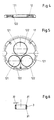
- 1 shows a side view of a mixing valve arranged in a special housing;
- 2 shows a bottom view of the mixing valve according to FIG. 1 with the bottom;
- FIG. 3 shows a partial section of the mixing valve according to FIG. 1 in the installed state in a sanitary fitting on an enlarged scale;
- Figure 4 shows the floor according to Figure 1 in section;
- Figure 5 shows the bottom of Figure 4 in plan view;
- Figure 6 shows a seal according to Figure 2 in section.
Das in der Zeichnung dargestellte Wassermischventil ist in einem Sondergehäuse 1 angeordnet und kann als Baueinheit in einen entsprechend ausgebildeten Sanitärarmaturenkörper 2 eingefügt werden. Das Sondergehäuse 1 besteht aus einer topfartigen Hülse 11 und einem axial in die Hülse 11 einschiebbaren Boden 12. In dem Sondergehäuse 1 ist eine im wesentlichen ortsfest gehalterte Ventilsitzscheibe 15 angeordnet, auf der eine mit einem Betätigungsorgan 13 verschiebbare Regelscheibe 14 gelagert ist. In der Ventilsitzscheibe 15 ist jeweils eine Durchtrittsöffnung für Kalt- und Warmwasser und eine Auslaßöffnung für Mischwasser ausgebildet. Mit Hilfe eines in der Regelscheibe 14 ausgebildeten Überströmkanals 141 können diese Öffnungen in Abhängigkeit von der Stellung der Regelscheibe 14 mehr oder weniger in Überdeckung gebracht werden und somit die Durchflußmenge und das Mischungsverhältnis von Kalt- und Warmwasser bestimmt werden.The water mixing valve shown in the drawing is arranged in a
Der Ventilsitzscheibe 15 ist der Boden 12 des Sondergehäuses 1 unmittelbar vorgelagert und weist entsprechende Öffnungen 121 für den Wasserdurchtritt auf. In dem der Ventilsitzscheibe 15 zugekehrten Bereich der Wandungen der Öffnungen 121 ist jeweils eine Einschnürung 122 ausgebildet, die sprungartig etwa 0,3 mm vor der Stirnseite des Bodens 12 etwa 0,4 mm den Durchmesser verringert. Die Einschnürung 122 weist somit eine in die Öffnung 121 vorkragende, umlaufende Kante auf. In den Öffnungen 121 sind außerdem schlauchförmige Dichtungen 3 aus gummielastischem Material angeordnet. Die Dichtungen 3 weisen dabei halbrundförmig ausgebildete Stirnflächen 31 auf und haben eine Wandstärke 32 von etwa 1,5 mm.The
Wie es insbesondere aus Figur 3 ersichtlich ist, stützt sich der Dichtring 3 im Bereich seiner halbrundförmig ausgebildeten Stirnseite an der Einschnürung 122 ab und bewirkt so bei einer Druckbeaufschlagung des Mischventils, daß der Boden 12 zusammen mit der Ventilsitzscheibe 15 in die topfartige Hülse 11 gedrückt wird. Eine Spaltausbildung zwischen Ventilsitzscheibe 15 und Boden 12 wird somit vermieden. Der durch die Ventilscheibenzusammenpressung entstehende Spalt zwischen Sanitärarmaturenkörper 2 und dem Boden 12 ist unschädlich, da die Dichtung 3 in diesem Bereich in einer ringförmigen Ausnehmung 21 des Sanitärarmaturenkörpers 2 gestützt wird.As can be seen particularly from FIG. 3, the
Die beiden im Durchmesser kleineren Öffnungen 121 sind für die Zuführung von Kalt- und Warmwasser vorgesehen, wenn die Warmwasserbereitung von einer zentralen Anlage erfolgt. Die Öffnung 121 mit dem größeren Durchmesser dient dann dem Ablauf des erzeugten Mischwassers. Wird dagegen das Warmwasser von einem drucklosen Warmwasserüberlaufspeicher bezogen, so erfolgt die Zuführung des Kaltwassers über die Öffnung 121 mit dem großen Durchmesser, während die Abführung in Teilströmen durch die Öffnungen 121 mit kleinem Durchmesser erfolgt. Hierbei wird der eine Teilstrom von Kaltwasser dem Warmwasserüberlaufspeicher zugeführt und eine entsprechende Menge Warmwasser vom Warmwasserspeicher der Sanitärarmatur wieder zugeführt, während der andere Teilstrom direkt in die Sanitärarmatur abgegeben wird, wo sich die beiden Teilströme mischen und temperiertes Wasser erzeugen.The two
Dadurch, daß alle drei Öffnungen 121 mit einer Einschnürung 122 versehen sind, kann das als Baueinheit ausgebildete Wassermischventil sowohl in Sanitärarmaturen, bei denen eine zentrale Warmwasserbereitung als auch bei denen eine Warmwasserbereitung über einen drucklosen Überlaufwarmwasserspeicher erfolgt, eingesetzt werden.Because all three
Claims (6)
Priority Applications (1)
| Application Number | Priority Date | Filing Date | Title |
|---|---|---|---|
| AT89115166T ATE75015T1 (en) | 1988-09-09 | 1989-08-17 | WATER MIXING VALVE. |
Applications Claiming Priority (2)
| Application Number | Priority Date | Filing Date | Title |
|---|---|---|---|
| DE3830700 | 1988-09-09 | ||
| DE3830700A DE3830700A1 (en) | 1988-09-09 | 1988-09-09 | WATER MIXING VALVE |
Publications (2)
| Publication Number | Publication Date |
|---|---|
| EP0359999A1 EP0359999A1 (en) | 1990-03-28 |
| EP0359999B1 true EP0359999B1 (en) | 1992-04-15 |
Family
ID=6362625
Family Applications (1)
| Application Number | Title | Priority Date | Filing Date |
|---|---|---|---|
| EP89115166A Expired - Lifetime EP0359999B1 (en) | 1988-09-09 | 1989-08-17 | Water mixing valve |
Country Status (6)
| Country | Link |
|---|---|
| US (1) | US4921016A (en) |
| EP (1) | EP0359999B1 (en) |
| AT (1) | ATE75015T1 (en) |
| DE (2) | DE3830700A1 (en) |
| ES (1) | ES2030950T3 (en) |
| GR (1) | GR3005018T3 (en) |
Families Citing this family (9)
| Publication number | Priority date | Publication date | Assignee | Title |
|---|---|---|---|---|
| US6019132A (en) * | 1996-10-01 | 2000-02-01 | Masco Corporation Of Indiana | Plug with anchored retaining packings for a cartridge for a water faucet |
| IT1288719B1 (en) * | 1996-10-01 | 1998-09-24 | Gevipi Ag | BOTTOM WITH ANCHORED SEALING GASKETS, FOR ONE HYDRAULIC TAP CARTRIDGE. |
| DE19811099A1 (en) | 1998-03-13 | 1999-09-16 | Grohe Armaturen Friedrich | Water valve |
| JP3632952B2 (en) * | 1999-12-27 | 2005-03-30 | 株式会社エンプラス | Valve unit and valve seat made of synthetic resin |
| EP1852558B1 (en) * | 2006-05-03 | 2009-11-25 | Kwc Ag | Internal housing for a sanitary fitting and sanitary fitting |
| DE102006036148A1 (en) * | 2006-07-31 | 2008-02-07 | Hansgrohe Ag | Mixer cartridge for insertion into sanitary fitting, has cartridge base closing cartridge housing in direction of retainer of sanitary fitting, where base is held opposite to cartridge housing in movable manner |
| CN101646889B (en) * | 2007-01-31 | 2012-01-11 | 莫恩股份有限公司 | Valve cartridge insensitive to installation load |
| US20150144214A1 (en) * | 2013-11-22 | 2015-05-28 | Chia-Po Chang | Mixed Water Control Valve for Faucet |
| DE102019003301A1 (en) * | 2019-05-10 | 2020-11-12 | Grohe Ag | Single lever cartridge for a sanitary fitting |
Family Cites Families (6)
| Publication number | Priority date | Publication date | Assignee | Title |
|---|---|---|---|---|
| BE794114A (en) * | 1972-07-20 | 1973-05-16 | Ideal Standard Sa | SINGLE LEVER MIXING VALVE |
| US4362186A (en) * | 1981-02-11 | 1982-12-07 | American Standard Inc. | Sanitary fitting |
| DE3202392C2 (en) * | 1982-01-26 | 1984-10-25 | Hansa Metallwerke Ag, 7000 Stuttgart | Single lever mixer valve |
| DE3503793C2 (en) * | 1985-02-05 | 1995-09-21 | Grohe Armaturen Friedrich | Mixing valve |
| DE8627223U1 (en) * | 1986-10-06 | 1986-11-20 | Ideal-Standard Gmbh, 5300 Bonn | Sanitary mixer tap |
| DE3738854A1 (en) * | 1987-11-16 | 1989-05-24 | Grohe Armaturen Friedrich | WATER MIXING VALVE |
-
1988
- 1988-09-09 DE DE3830700A patent/DE3830700A1/en not_active Withdrawn
-
1989
- 1989-08-17 EP EP89115166A patent/EP0359999B1/en not_active Expired - Lifetime
- 1989-08-17 ES ES198989115166T patent/ES2030950T3/en not_active Expired - Lifetime
- 1989-08-17 AT AT89115166T patent/ATE75015T1/en not_active IP Right Cessation
- 1989-08-17 DE DE8989115166T patent/DE58901164D1/en not_active Expired - Fee Related
- 1989-09-07 US US07/404,304 patent/US4921016A/en not_active Expired - Lifetime
-
1992
- 1992-06-24 GR GR920401358T patent/GR3005018T3/el unknown
Also Published As
| Publication number | Publication date |
|---|---|
| DE58901164D1 (en) | 1992-05-21 |
| EP0359999A1 (en) | 1990-03-28 |
| US4921016A (en) | 1990-05-01 |
| ES2030950T3 (en) | 1992-11-16 |
| GR3005018T3 (en) | 1993-05-24 |
| DE3830700A1 (en) | 1990-03-15 |
| ATE75015T1 (en) | 1992-05-15 |
Similar Documents
| Publication | Publication Date | Title |
|---|---|---|
| DE3515591C2 (en) | Mixer tap with valve disks made of a hard material and with a pressure-loaded insert | |
| EP0271765B1 (en) | Self fluid controlled valve releasable by an especially solenoid controlled pilot valve | |
| DE2150825B2 (en) | Quiet faucet | |
| DE2225740C3 (en) | Mixer tap for stepless adjustment of the mixing ratio between two liquids and the total flow rate | |
| DE2312520A1 (en) | VALVE CARTRIDGE FOR WATER TAP O.DGL | |
| DE2211046B2 (en) | Control device for a heat exchanger connected to a flow system, in particular for a radiator | |
| EP0359999B1 (en) | Water mixing valve | |
| DE102005052385B4 (en) | pressure reducer | |
| DE1550177B1 (en) | Cone valve with sealing plates arranged with play in the plug | |
| DE102011084837A1 (en) | Valve cartridge for a sanitary fitting | |
| DE10146277A1 (en) | water fitting | |
| DE3991752C2 (en) | Cartridge for single control lever mixing faucet | |
| EP3105380A1 (en) | Fixture having a pivoting outlet | |
| EP0311598B1 (en) | Valve cartridge for a one-way valve | |
| EP3105381A1 (en) | Fitting having a pivoting outlet | |
| DE10083312B4 (en) | sealing device | |
| DE8603917U1 (en) | Check valve with a two-part or multi-part housing for medical purposes | |
| DE2900601A1 (en) | BARRIER | |
| DE2907565C2 (en) | Combined self-closing and mixing valve | |
| DE29800726U1 (en) | Valve counter with shut-off device | |
| DE1169236B (en) | Double seat valve, especially multi-way solenoid valve | |
| DE2528244A1 (en) | Non-return valve designed as insert plug - has spherical closing plug with pressure spring and supported plate spring | |
| DE3446425C2 (en) | Backflow preventer for a fluid | |
| DE29517768U1 (en) | Directional control valve for controlling a pressure medium flow | |
| DE3225934A1 (en) | Sanitary single-lever mixer |
Legal Events
| Date | Code | Title | Description |
|---|---|---|---|
| PUAI | Public reference made under article 153(3) epc to a published international application that has entered the european phase |
Free format text: ORIGINAL CODE: 0009012 |
|
| AK | Designated contracting states |
Kind code of ref document: A1 Designated state(s): AT BE CH DE ES FR GB GR IT LI NL SE |
|
| 17P | Request for examination filed |
Effective date: 19900516 |
|
| 17Q | First examination report despatched |
Effective date: 19910722 |
|
| GRAA | (expected) grant |
Free format text: ORIGINAL CODE: 0009210 |
|
| RAP1 | Party data changed (applicant data changed or rights of an application transferred) |
Owner name: FRIEDRICH GROHE AKTIENGESELLSCHAFT |
|
| AK | Designated contracting states |
Kind code of ref document: B1 Designated state(s): AT BE CH DE ES FR GB GR IT LI NL SE |
|
| REF | Corresponds to: |
Ref document number: 75015 Country of ref document: AT Date of ref document: 19920515 Kind code of ref document: T |
|
| REF | Corresponds to: |
Ref document number: 58901164 Country of ref document: DE Date of ref document: 19920521 |
|
| ITF | It: translation for a ep patent filed | ||
| PGFP | Annual fee paid to national office [announced via postgrant information from national office to epo] |
Ref country code: GR Payment date: 19920721 Year of fee payment: 4 |
|
| ET | Fr: translation filed | ||
| PGFP | Annual fee paid to national office [announced via postgrant information from national office to epo] |
Ref country code: SE Payment date: 19920728 Year of fee payment: 4 |
|
| GBT | Gb: translation of ep patent filed (gb section 77(6)(a)/1977) | ||
| PGFP | Annual fee paid to national office [announced via postgrant information from national office to epo] |
Ref country code: BE Payment date: 19920827 Year of fee payment: 4 |
|
| PGFP | Annual fee paid to national office [announced via postgrant information from national office to epo] |
Ref country code: NL Payment date: 19920831 Year of fee payment: 4 |
|
| REG | Reference to a national code |
Ref country code: ES Ref legal event code: FG2A Ref document number: 2030950 Country of ref document: ES Kind code of ref document: T3 |
|
| PLBE | No opposition filed within time limit |
Free format text: ORIGINAL CODE: 0009261 |
|
| STAA | Information on the status of an ep patent application or granted ep patent |
Free format text: STATUS: NO OPPOSITION FILED WITHIN TIME LIMIT |
|
| REG | Reference to a national code |
Ref country code: GR Ref legal event code: FG4A Free format text: 3005018 |
|
| 26N | No opposition filed | ||
| PG25 | Lapsed in a contracting state [announced via postgrant information from national office to epo] |
Ref country code: GB Effective date: 19930817 |
|
| PG25 | Lapsed in a contracting state [announced via postgrant information from national office to epo] |
Ref country code: SE Effective date: 19930818 |
|
| PG25 | Lapsed in a contracting state [announced via postgrant information from national office to epo] |
Ref country code: BE Effective date: 19930831 |
|
| BERE | Be: lapsed |
Owner name: FRIEDRICH GROHE A.G. Effective date: 19930831 |
|
| PG25 | Lapsed in a contracting state [announced via postgrant information from national office to epo] |
Ref country code: GR Free format text: THE PATENT HAS BEEN ANNULLED BY A DECISION OF A NATIONAL AUTHORITY Effective date: 19940228 |
|
| PG25 | Lapsed in a contracting state [announced via postgrant information from national office to epo] |
Ref country code: NL Effective date: 19940301 |
|
| GBPC | Gb: european patent ceased through non-payment of renewal fee |
Effective date: 19930817 |
|
| NLV4 | Nl: lapsed or anulled due to non-payment of the annual fee | ||
| REG | Reference to a national code |
Ref country code: GR Ref legal event code: MM2A Free format text: 3005018 |
|
| EUG | Se: european patent has lapsed |
Ref document number: 89115166.4 Effective date: 19940310 |
|
| REG | Reference to a national code |
Ref country code: CH Ref legal event code: PFA Free format text: FRIEDRICH GROHE AKTIENGESELLSCHAFT TRANSFER- FRIEDRICH GROHE AG & CO. KG |
|
| REG | Reference to a national code |
Ref country code: FR Ref legal event code: CJ |
|
| REG | Reference to a national code |
Ref country code: ES Ref legal event code: PC2A |
|
| PGFP | Annual fee paid to national office [announced via postgrant information from national office to epo] |
Ref country code: DE Payment date: 20040805 Year of fee payment: 16 |
|
| PGFP | Annual fee paid to national office [announced via postgrant information from national office to epo] |
Ref country code: CH Payment date: 20040811 Year of fee payment: 16 |
|
| PGFP | Annual fee paid to national office [announced via postgrant information from national office to epo] |
Ref country code: AT Payment date: 20040826 Year of fee payment: 16 |
|
| PGFP | Annual fee paid to national office [announced via postgrant information from national office to epo] |
Ref country code: FR Payment date: 20040830 Year of fee payment: 16 |
|
| PGFP | Annual fee paid to national office [announced via postgrant information from national office to epo] |
Ref country code: ES Payment date: 20040917 Year of fee payment: 16 |
|
| PG25 | Lapsed in a contracting state [announced via postgrant information from national office to epo] |
Ref country code: IT Free format text: LAPSE BECAUSE OF NON-PAYMENT OF DUE FEES;WARNING: LAPSES OF ITALIAN PATENTS WITH EFFECTIVE DATE BEFORE 2007 MAY HAVE OCCURRED AT ANY TIME BEFORE 2007. THE CORRECT EFFECTIVE DATE MAY BE DIFFERENT FROM THE ONE RECORDED. Effective date: 20050817 Ref country code: AT Free format text: LAPSE BECAUSE OF NON-PAYMENT OF DUE FEES Effective date: 20050817 |
|
| PG25 | Lapsed in a contracting state [announced via postgrant information from national office to epo] |
Ref country code: ES Free format text: LAPSE BECAUSE OF NON-PAYMENT OF DUE FEES Effective date: 20050818 |
|
| PG25 | Lapsed in a contracting state [announced via postgrant information from national office to epo] |
Ref country code: LI Free format text: LAPSE BECAUSE OF NON-PAYMENT OF DUE FEES Effective date: 20050831 Ref country code: CH Free format text: LAPSE BECAUSE OF NON-PAYMENT OF DUE FEES Effective date: 20050831 |
|
| PG25 | Lapsed in a contracting state [announced via postgrant information from national office to epo] |
Ref country code: DE Free format text: LAPSE BECAUSE OF NON-PAYMENT OF DUE FEES Effective date: 20060301 |
|
| REG | Reference to a national code |
Ref country code: CH Ref legal event code: PL |
|
| PG25 | Lapsed in a contracting state [announced via postgrant information from national office to epo] |
Ref country code: FR Free format text: LAPSE BECAUSE OF NON-PAYMENT OF DUE FEES Effective date: 20060428 |
|
| REG | Reference to a national code |
Ref country code: FR Ref legal event code: ST Effective date: 20060428 |
|
| REG | Reference to a national code |
Ref country code: ES Ref legal event code: FD2A Effective date: 20050818 |