EP0359728B1 - Locking device for a door of a washing machine, a spin dryer or the like - Google Patents
Locking device for a door of a washing machine, a spin dryer or the like Download PDFInfo
- Publication number
- EP0359728B1 EP0359728B1 EP89850271A EP89850271A EP0359728B1 EP 0359728 B1 EP0359728 B1 EP 0359728B1 EP 89850271 A EP89850271 A EP 89850271A EP 89850271 A EP89850271 A EP 89850271A EP 0359728 B1 EP0359728 B1 EP 0359728B1
- Authority
- EP
- European Patent Office
- Prior art keywords
- blocking
- locking
- plate
- catch member
- blocking means
- Prior art date
- Legal status (The legal status is an assumption and is not a legal conclusion. Google has not performed a legal analysis and makes no representation as to the accuracy of the status listed.)
- Expired - Lifetime
Links
Images

Classifications
-
- D—TEXTILES; PAPER
- D06—TREATMENT OF TEXTILES OR THE LIKE; LAUNDERING; FLEXIBLE MATERIALS NOT OTHERWISE PROVIDED FOR
- D06F—LAUNDERING, DRYING, IRONING, PRESSING OR FOLDING TEXTILE ARTICLES
- D06F37/00—Details specific to washing machines covered by groups D06F21/00 - D06F25/00
- D06F37/42—Safety arrangements, e.g. for stopping rotation of the receptacle upon opening of the casing door
-
- D—TEXTILES; PAPER
- D06—TREATMENT OF TEXTILES OR THE LIKE; LAUNDERING; FLEXIBLE MATERIALS NOT OTHERWISE PROVIDED FOR
- D06F—LAUNDERING, DRYING, IRONING, PRESSING OR FOLDING TEXTILE ARTICLES
- D06F39/00—Details of washing machines not specific to a single type of machines covered by groups D06F9/00 - D06F27/00
- D06F39/12—Casings; Tubs
- D06F39/14—Doors or covers; Securing means therefor
-
- Y—GENERAL TAGGING OF NEW TECHNOLOGICAL DEVELOPMENTS; GENERAL TAGGING OF CROSS-SECTIONAL TECHNOLOGIES SPANNING OVER SEVERAL SECTIONS OF THE IPC; TECHNICAL SUBJECTS COVERED BY FORMER USPC CROSS-REFERENCE ART COLLECTIONS [XRACs] AND DIGESTS
- Y10—TECHNICAL SUBJECTS COVERED BY FORMER USPC
- Y10S—TECHNICAL SUBJECTS COVERED BY FORMER USPC CROSS-REFERENCE ART COLLECTIONS [XRACs] AND DIGESTS
- Y10S292/00—Closure fasteners
- Y10S292/69—Washing machine or stove closure latch
-
- Y—GENERAL TAGGING OF NEW TECHNOLOGICAL DEVELOPMENTS; GENERAL TAGGING OF CROSS-SECTIONAL TECHNOLOGIES SPANNING OVER SEVERAL SECTIONS OF THE IPC; TECHNICAL SUBJECTS COVERED BY FORMER USPC CROSS-REFERENCE ART COLLECTIONS [XRACs] AND DIGESTS
- Y10—TECHNICAL SUBJECTS COVERED BY FORMER USPC
- Y10T—TECHNICAL SUBJECTS COVERED BY FORMER US CLASSIFICATION
- Y10T292/00—Closure fasteners
- Y10T292/08—Bolts
- Y10T292/0911—Hooked end
- Y10T292/0945—Operating means
- Y10T292/0951—Rigid
- Y10T292/0959—Swinging catch
-
- Y—GENERAL TAGGING OF NEW TECHNOLOGICAL DEVELOPMENTS; GENERAL TAGGING OF CROSS-SECTIONAL TECHNOLOGIES SPANNING OVER SEVERAL SECTIONS OF THE IPC; TECHNICAL SUBJECTS COVERED BY FORMER USPC CROSS-REFERENCE ART COLLECTIONS [XRACs] AND DIGESTS
- Y10—TECHNICAL SUBJECTS COVERED BY FORMER USPC
- Y10T—TECHNICAL SUBJECTS COVERED BY FORMER US CLASSIFICATION
- Y10T292/00—Closure fasteners
- Y10T292/175—Bolt releasers
- Y10T292/18—Free-end-engaging means
-
- Y—GENERAL TAGGING OF NEW TECHNOLOGICAL DEVELOPMENTS; GENERAL TAGGING OF CROSS-SECTIONAL TECHNOLOGIES SPANNING OVER SEVERAL SECTIONS OF THE IPC; TECHNICAL SUBJECTS COVERED BY FORMER USPC CROSS-REFERENCE ART COLLECTIONS [XRACs] AND DIGESTS
- Y10—TECHNICAL SUBJECTS COVERED BY FORMER USPC
- Y10T—TECHNICAL SUBJECTS COVERED BY FORMER US CLASSIFICATION
- Y10T292/00—Closure fasteners
- Y10T292/68—Keepers
- Y10T292/696—With movable dog, catch or striker
- Y10T292/702—Pivoted or swinging
Landscapes
- Engineering & Computer Science (AREA)
- Textile Engineering (AREA)
- Main Body Construction Of Washing Machines And Laundry Dryers (AREA)
Description
- The present invention refers to a locking device in a door of a washing machine, a spin dryer or the like according to the preamble of the following claim 1.
- In industrial washing machines multispeed motors provided with a free wheel mechanism are being used. In stopping the washing drum of such a machine the motor is switched off, however, no braking takes place. In a large machine, for example taking 80 kg of laundry, it may take upp to five minutes before the drum has come to a complete stop.
- The purpose of the locking device is to prevent opening of the door until the drum has stopped. In this connection there is a desire for the possibility of opening the door even in case of power failure. This wish can be met with by using a bimetal lock wherein a bimetal operated catch member is kept in a blocking position by an electric current heating the bimetal. In case of power failure the heating current will cease and the catch member will move from the blocking position to a lock releasing position. However, bimetal locks are sensitive to temperature which causes a great variation in the time of change from the blocking to the releasing position.
- The time to lapse before the door of the machine can be opened has to be chosen so long that in any case the drum has stopped before opening can take place. The drum stopping time varies with the amount of laundry and also depends on whether the machine is new or old (the drum rotates more easily in an old machine).
- When using a bimetal lock in a machine of the kind referred to the variation in the change-over time has to be combined with varying drum stopping times which very easily causes unacceptably long waiting times before the door can be opened. One solution of the problem is the use of a rotational movement sensor which upon stopping of the drum operates a control device which releases the door lock. Such solutions are described in the patent publications DE-A-2,163,449 and DE-A-2,318,363.
- Moreover, DE-A-2 017 664 discloses a locking device for a door in a washing machine in which a pivotable locking member is disposed in the machine and cooperates with a catch member disposed on the door of said machine. Upon closing of the door the catch member operates on the locking member turning it to its locking position. During the turning movement the locking member displaces an elongate plate member from a lock releasing position into a locking position in which said plate member is retained by means which can be operated into a plate releasing position upon actuation of a solenoid device.
- EP-A-0 007 637 discloses a locking device for a door in a washing machine in which a locking member can be operated to take either of two stable positions, namely a locking position and a lock releasing position, respectively. A driving device is provided which is operated by pulses from a microprocessor or the like to act so as to bring the locking member to the lock releasing position when said member is in the locking position and, alternatively, to bring the locking member to the locking position when said member is in the lock releasing position.
- In a further known washing machine in which the lock releasing process is controlled by a rotational movement sensor a catch member of the lock is operated to take its blocking and lock releasing positions, respectively, by two separate electromagnets. This means that even if the catch member can be activated to block the lock a fault may occur on the other electromagnet causing a situation where the lock cannot be released and, accordingly, the door cannot be opened. In connection with so-called coin-operated washing machines in self-service shops such a situation may result in locks being broken as the customers cannot get their laundry out. For the same reason the door lock must be releasable in case of power failure. This will not take place automatically in case of locks controlled by a rotational movement sensor as when the lock is operated by a bimetal.
- In the light of the prior art technique described above it is an object of the invention to provide a locking device having an electrically operable catch member of a design such that the same operating means be active both when the catch member is to be moved to the blocking position and when it is to be moved to the releasing position. In this way the catch member taking its blocking position will serve as a receipt of the fact that the operating means is functioning and, accordingly, with great probability the operating means will function also during the course of the lock opening to follow.
- Another object is to simplify the known device having two separate operating means and, hence, to reduce the costs of manufacture.
- A third object is to make possible the use of a swingable blocking means including a plate, wherein the angular position of engagement of the blocking means with the catch member for preventing movement of same differs from the angular position of the plate which constitutes the blocking position of the blocking means.
- The objects indicated have been achieved in a locking device having the characterizing features indicated in claim 1. Preferred embodiments appear from the appending sub-claims.
- The invention will now be described more in detail in connection with an embodiment with reference to the enclosed drawings.
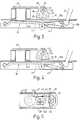
- Figs. 1-4
- schematically show a door lock according to the invention. The figures are side views, partly in section, showing the lock in different positions of operation.
- Fig. 5
- shows the door lock of Figs. 1-4 in a bottom view.
- The door lock is built-up on a
base 10 which by means, not shown, is secured adjacent to the loading opening of a washing machine, not shown. The base is provided with alocking plate 10a having anopening 11 through which acatch 12 can be inserted. The catch is pivotably journalled on a door, not shown, closing the loading opening. Moreover, by spring means the catch is biased to the position shown in Fig. 2 where anedge 13 on the catch falls in behind anedge 14 bounding theopening 11. By maneuvering of an operating member on the door, not shown, the catch can be turned against the action of the spring means to the position shown in Fig. 1 in order for the door to be opened. - When the washing machine is operating it shall not be possible to open the door. For this purpose a
blocking plate 15 is provided with anopening 16 which, as shown in Fig. 2, surrounds apart 12a of thecatch 12 inserted through theopening 11. Anedge 44 bounding the opening 16 of the blocking plate bears on thepart 12a of thecatch 12 preventing it from moving away from the locking position. Along part of its length theblocking plate 15 is fixedly secured to aplate 17 acting as a support forplate 15. The two plates are so interconnected that the blocking plate is given the shape of a V the legs of which are directed towards thelocking plate 10a. The opposite end of the blocking plate forms with the plate 17 ajournalling sleeve 18 by which theunit 19 formed by theblocking plate 15 and thesupport plate 17 is pivotably journalled on apin 20 fixed to thebase 10. By a spring 21, Fig. 5, theunit 19 is biased to the position shown in Fig. 3, which is the lock releasing position of the blocking plate. - For operating the
unit 19 and hence theblocking plate 15 anelectromagnet 22 is provided which has an excitation winding 23 connected to a control device, not shown. In a manner not described in detail the control device co-operates with a programmer provided for the control of the washing machine. Theelectromagnet 22 is acting as a pulling magnet attracting when activated theunit 19 which forms the movable armature of the magnet. Fig. 2 shows this condition which appears when thecatch 12 is to be blocked and when it is to be released as well. The electromagnet co-operates with aseparate mechanism 24 in order to keep the blocking plate in the blocking position (Fig. 3) and in the lock releasing position (Fig. 1), respectively. The mechanism comprises awire bow 25 which is turnably journalled by apart 25a entering a journalling hole in asheet metal bracket 26. Theopposite end 25b of the wire bow co-operates with a guiding track 27 provided in aguide plate 28. The guiding track comprises tworest positions blocking plate 15 and to the lock releasing position, Fig. 1, thereof (see also Fig. 2). The guiding track also comprises twotemporary rest positions rest positions opposite end 25b taking any of the saidtemporary rest positions unit 19 is permitted to move to a position wherein the blockingplate 15 bears on thelocking plate 10a. - The guiding track extends inwards into the plane of the paper and has a bottom part provided with
steps end 25b of the wire bow extends perpendicular to the plane of the paper towards the bottom of the track against which it is biased by aspring 45. - As appears from Fig. 3, when the
wire bow 25 has taken therest position 29 theplate 17 has taken a position between the position shown in Fig. 2 and the position shown in Fig. 1. However, due to the V-shape of the blocking plate the end of the blocking plate having theopening 16 will still in this position engage with thecatch 12 to block it. The blocking plate is made of resilient material permitting movement of theunit 19 to the position shown in Figs. 2 and 4. - The
steps magnet 22 is activated and the wire bow is in therest position 30 the wire bow will be moved along thestep 33 and part ofstep 34 to thetemporary rest position 31. Then, when the magnet is inactivated the wire bow is moved viasteps rest position 29 where it remains. This course is shown in Figs. 2 and 3 where Fig. 2 shows the positions of the wire bow and theunit 19, respectively, when, starting from the position shown in Fig. 1 with a catch taking its locking position (Fig. 2), themagnet 22 has been activated. In Fig. 3 there are shown the positions of the wire bow and theunit 19 with the blockingplate 15, respectively, when the magnet has been inactivated. Here, the blocking plate has taken its blocking position. Next time themagnet 22 is activated thewire bow 25 is moved viastep 35 and part ofstep 36 to thetemporary rest position 32 and upon the following inactivation of the magnet the wire bow will be guided viastep 36 and part ofstep 33 back to therest position 30 causing theunit 19 to take the position shown in Fig. 1 and the blocking plate to take its lock releasing position. - In case the
catch 12 has not taken its locking position, Fig. 2, it shall not be possible to move the blockingplate 15 to its blocking position. For this purpose a blocking device is provided in the shape of awire bow 39 journalled in twoside parts 37, 38 of thebase 10. Thewire bow 39 has twoparts part 41 is biased in a clockwise direction by aspring 42, see Figs. 1-4. When thecatch 12 is absent thewire bow 39 is turned to the position shown in Fig. 1 where thepart 41 falls into the way of movement of anabutment 43 disposed on the blockingplate 15. When themagnet 22 is activated thewire bow 39 will be clamped between theabutment 43 and thelocking plate 10a blocking the further movement ofunit 19. When the catch is moved to the position shown in Fig. 2 thepart 12a acts on thepart 40 of thewire bow 39 causing thepart 41 to be moved out of the way of movement of theabutment 43.
Claims (4)
- A locking device for a door of a washing machine, a spin dryer or the like, comprising a locking plate (10a) disposed on the machine and having a first opening (11), and a catch member (12) disposed on the door to be insertable in said first opening, the catch member in a locking position engaging with an edge (14), bounding the first opening (11), to keep the door closed, an electrically operable blocking means (19) being provided to prevent the catch member (12) from moving from the locking position as long as a a rotatable drum or the like in the machine is operating, releasing means (22,24,25) being provided to release the blocking means (19) as soon as the rotational movement has ceased, and electrical drive means (22) being provided for moving the blocking means (19) to a blocking position against the action of a biasing means (21) which strives to move the blocking means (19) to a lock releasing position, the electrical drive means (22) co-operating with a mechanism (24) of a design such that upon activation of the drive means (22) the blocking means (19) is operated to alternatingly take the blocking position and the lock releasing position, respectively, wherein the drive means (22) is an electromagnet, the movable armature of which is constituted by the blocking means (19) which has a part (15) provided with a second opening (16), said part in the blocking position of the blocking means (19) surrounding the catch member (12), wherein an edge (44) bounding the second opening (16) operates to block the catch member (12) in its locking position, characterized in that the blocking means (19) comprises a pivotably journalled plate (17) which when the electromagnet (22) is activated takes a position in which it extends mainly parallel to the locking plate (10a), the part of the blocking means (19) incorporating the second opening (16) being formed by a blocking plate (15) made of resilient material and being secured to the pivotable plate (17) in such a way that in the blocking position of the blocking means (19) the blocking plate (15) has the shape of a V, the legs of which are facing the locking plate (10a).
- A locking device according to claim 1, characterized in that the mechanism (24) co-operating with the drive means (22) comprises a wire bow (25) or the like movably secured to the pivotable plate (17) and having one end (25b) which co-operates with a guiding track (27) having two rest positions (29,30) corresponding to the blocking position and the lock releasing position, respectively, of the blocking means (19), and two temporary rest positions (31,32) disposed between the said rest position (29,30), the wire bow (25) alternatingly taking one (31) or the other (32) of the temporary rest positions when, with the electromagnet being activated, the pivotable plate (17) of the blocking means (19), in compressing the blocking plate (15), takes the position in which it extends parallel to the locking plate (10a).
- A locking plate according to any of the preceding claims, characterized in that a blocking device (39,40,41;43) is provided to prevent the blocking device (19) from moving to the blocking position in case the catch member (12) has not taken the locking position.
- A locking device according to claim 3, characterized in that the blocking device comprises a wire bow (39) pivotably journalled in the machine and having two parts (40,41) disposed at both sides of the journalling axis and forming levers, one (40) of said parts co-operating with the catch member (12) and the other part co-operating with an abutment (43) provided on the blocking means (19), said blocking device (39,40,41) in its blocking position co-operating with the abutment (43) to prevent the blocking means (19) from moving to its blocking position while the catch member (12), when taking its locking position, engages with the wire bow (39) to turn it to a position in which said movement of the blocking means (19) is permitted.
Applications Claiming Priority (2)
| Application Number | Priority Date | Filing Date | Title |
|---|---|---|---|
| SE8803289 | 1988-09-16 | ||
| SE8803289A SE461989B (en) | 1988-09-16 | 1988-09-16 | LOADING MACHINE FOR A CLOSER TO A WASHER, CENTRIFUG |
Publications (3)
| Publication Number | Publication Date |
|---|---|
| EP0359728A2 EP0359728A2 (en) | 1990-03-21 |
| EP0359728A3 EP0359728A3 (en) | 1990-08-08 |
| EP0359728B1 true EP0359728B1 (en) | 1994-05-18 |
Family
ID=20373362
Family Applications (1)
| Application Number | Title | Priority Date | Filing Date |
|---|---|---|---|
| EP89850271A Expired - Lifetime EP0359728B1 (en) | 1988-09-16 | 1989-08-25 | Locking device for a door of a washing machine, a spin dryer or the like |
Country Status (4)
| Country | Link |
|---|---|
| US (1) | US4932707A (en) |
| EP (1) | EP0359728B1 (en) |
| DE (1) | DE68915373T2 (en) |
| SE (1) | SE461989B (en) |
Families Citing this family (27)
| Publication number | Priority date | Publication date | Assignee | Title |
|---|---|---|---|---|
| US5004276A (en) * | 1990-01-22 | 1991-04-02 | The Stanley Works | Push to close latch for self-cleaning oven |
| US5072974A (en) * | 1991-02-07 | 1991-12-17 | The Stanley Works | Push to close latch for self-cleaning oven |
| US5174618A (en) * | 1991-12-09 | 1992-12-29 | Maytag Corporation | Door latch assembly |
| US5401067A (en) * | 1992-06-10 | 1995-03-28 | Nifco, Inc. | Latch device |
| KR0122137Y1 (en) * | 1993-09-21 | 1998-10-01 | 김광호 | The open and close apparatus of a washing machine's door |
| ES2081760B1 (en) * | 1993-11-15 | 1998-11-01 | Anell Ramon Baraut | IMPROVEMENTS IN THE MACHINES FOR THE CARPEN SPIN. |
| DE19549197A1 (en) * | 1995-08-04 | 1997-02-06 | Ellenberger & Poensgen | Washing machine or drier door closure unit - comprises closure hook and electronically controlled holding member |
| US6048001A (en) * | 1997-03-31 | 2000-04-11 | Miller; Seth A. | Push-button actuated latching mechanism |
| IT1296669B1 (en) * | 1997-12-22 | 1999-07-14 | Bitron Spa | DEVICE FOR LOCKING AND UNLOCKING A DOOR OF A HOUSEHOLD APPLIANCE. |
| US6036241A (en) * | 1998-03-11 | 2000-03-14 | Maytag Corporation | Locking mechanism for an appliance door |
| ITTO980511A1 (en) * | 1998-06-11 | 1999-12-13 | Bitron Spa | DEVICE FOR LOCKING A DOOR OF A DOMESTIC APPLIANCE. |
| US6363755B1 (en) * | 1999-12-07 | 2002-04-02 | Ark-Les Corporation | Timed release washing machine lid lock |
| DE10038376C2 (en) * | 2000-08-07 | 2003-04-30 | Zangenstein Elektro | Door lock for the door of an electrical household appliance |
| DE50009661D1 (en) * | 2000-12-22 | 2005-04-07 | Zangenstein Elektro | Device for locking and releasing a door lock of an electrical device |
| US6679572B2 (en) | 2001-02-14 | 2004-01-20 | Maytag Corporation | Lid or door for household appliances |
| TW513548B (en) * | 2001-05-08 | 2002-12-11 | Mosel Vitelic Inc | Cover sensing system of spin dryer |
| US7492273B2 (en) | 2003-03-10 | 2009-02-17 | Walter Kidde Portable Equipment, Inc. | Pivoting battery carrier and a life safety device incorporating the same |
| US7900979B2 (en) * | 2003-06-27 | 2011-03-08 | Illinois Tool Works, Inc. | Low power consumption lock for appliance latch |
| EP1740752B1 (en) | 2004-04-27 | 2013-03-27 | Marquardt GmbH | Lock for a household appliance |
| ITTO20050333A1 (en) * | 2005-05-17 | 2006-11-18 | Itw Ind Components Srl | DOOR LOCK DEVICE FOR A APPLIANCE, IN PARTICULAR A PYROLYTIC OVEN |
| US7858307B2 (en) * | 2005-08-09 | 2010-12-28 | Maxwell Sensors, Inc. | Light transmitted assay beads |
| US7390045B2 (en) * | 2006-06-15 | 2008-06-24 | International Automotive Components Group North America, Inc. | System for attaching an article holding assembly to a mounting member in a vehicle |
| US8246089B2 (en) * | 2006-10-28 | 2012-08-21 | Marquardt Gmbh | Lock for a household appliance |
| ITTO20070476A1 (en) * | 2007-06-29 | 2008-12-30 | Itw Metalflex Druzba Za Proizv | ELECTROMAGNETIC LOCKING DEVICE FOR A DOOR OF A HOUSEHOLD APPLIANCE, IN PARTICULAR A PORT OF A WASHING MACHINE |
| PL2278058T3 (en) * | 2009-07-17 | 2016-09-30 | A device for locking the porthole door of washing and drying machines | |
| DE102019005564B3 (en) * | 2019-05-10 | 2020-09-17 | Emz-Hanauer Gmbh & Co. Kgaa | Door lock for an electrical household appliance |
| WO2023122814A1 (en) * | 2021-12-30 | 2023-07-06 | STIWA Advanced Products GmbH | Actuator device having a restoring element |
Family Cites Families (6)
| Publication number | Priority date | Publication date | Assignee | Title |
|---|---|---|---|---|
| DE2017664A1 (en) * | 1970-04-14 | 1971-10-28 | Trumpf Schloss U Beschlagfabri | Electromagnetically unlockable lock for washing machines or the like |
| DE2163449A1 (en) * | 1971-12-21 | 1973-07-05 | Miele & Cie | DOOR LOCKING FOR A WASHING MACHINE OR SPINTER |
| IT994158B (en) * | 1973-08-21 | 1975-10-20 | Texas Instruments Italia Spa | LOCKING DEVICE WITH VOLTMETRIC OPERATED THERMAL DELAY SWITCH FOR DOORS |
| DE2833860A1 (en) * | 1978-08-02 | 1980-02-21 | Ellenberger & Poensgen | BISTABLE LOCKING DEVICE FOR WASHING MACHINE DOORS |
| US4702506A (en) * | 1984-06-29 | 1987-10-27 | Kyosuke Iimura | Magnet catcher for doors |
| US4776620A (en) * | 1986-09-29 | 1988-10-11 | Whirlpool Corporation | Door latch for dishwasher |
-
1988
- 1988-09-16 SE SE8803289A patent/SE461989B/en not_active IP Right Cessation
-
1989
- 1989-08-01 US US07/388,154 patent/US4932707A/en not_active Expired - Fee Related
- 1989-08-25 EP EP89850271A patent/EP0359728B1/en not_active Expired - Lifetime
- 1989-08-25 DE DE68915373T patent/DE68915373T2/en not_active Expired - Lifetime
Also Published As
| Publication number | Publication date |
|---|---|
| EP0359728A3 (en) | 1990-08-08 |
| SE461989B (en) | 1990-04-23 |
| SE8803289L (en) | 1990-03-17 |
| US4932707A (en) | 1990-06-12 |
| DE68915373D1 (en) | 1994-06-23 |
| SE8803289D0 (en) | 1988-09-16 |
| DE68915373T2 (en) | 1994-10-20 |
| EP0359728A2 (en) | 1990-03-21 |
Similar Documents
| Publication | Publication Date | Title |
|---|---|---|
| EP0359728B1 (en) | Locking device for a door of a washing machine, a spin dryer or the like | |
| US3910617A (en) | Solenoid operated electric strike | |
| EP0588041B1 (en) | Improvement in a door interlock arrangement for washing machines | |
| EP0965677B1 (en) | A door locking device for an electric household appliance | |
| CA1161470A (en) | Electromechanical lid latch assembly | |
| US4012063A (en) | Interlock latch assembly for centrifugals | |
| JPH02192626A (en) | Locking mechanism for current-limiting contactor | |
| JP3967600B2 (en) | Lid lock device for washing machine | |
| JP2002119793A (en) | Washing machine and its drying operation control method | |
| JPS5810118B2 (en) | Kaiheibuta no Anzensouchi | |
| JPH0110693Y2 (en) | ||
| JP3726300B2 (en) | Vending machine locking device | |
| JPH0342526Y2 (en) | ||
| JP3756962B2 (en) | Amusement machine with door | |
| JP3271512B2 (en) | Circuit breaker double closing prevention device | |
| US3792764A (en) | Device for automatic closure of coin slot of rental locker | |
| JPH0896670A (en) | Operation device of circuit breaker | |
| JPH1161752A (en) | Electrically driven crossing gate and trouble prevention method by electrically driven crossing gate in power failure | |
| JPH0240693Y2 (en) | ||
| JP3623291B2 (en) | Electric shutter | |
| JPS6242112B2 (en) | ||
| JPH0530221Y2 (en) | ||
| JPS5816056Y2 (en) | Vending machine control circuit | |
| JPS636734Y2 (en) | ||
| JPS642615Y2 (en) |
Legal Events
| Date | Code | Title | Description |
|---|---|---|---|
| PUAI | Public reference made under article 153(3) epc to a published international application that has entered the european phase |
Free format text: ORIGINAL CODE: 0009012 |
|
| AK | Designated contracting states |
Kind code of ref document: A2 Designated state(s): DE GB IT |
|
| PUAL | Search report despatched |
Free format text: ORIGINAL CODE: 0009013 |
|
| AK | Designated contracting states |
Kind code of ref document: A3 Designated state(s): DE GB IT |
|
| 17P | Request for examination filed |
Effective date: 19910126 |
|
| 17Q | First examination report despatched |
Effective date: 19920917 |
|
| GRAA | (expected) grant |
Free format text: ORIGINAL CODE: 0009210 |
|
| AK | Designated contracting states |
Kind code of ref document: B1 Designated state(s): DE GB IT |
|
| REF | Corresponds to: |
Ref document number: 68915373 Country of ref document: DE Date of ref document: 19940623 |
|
| ITF | It: translation for a ep patent filed |
Owner name: PROPRIA PROT. PROPRIETA' IND. |
|
| PLBE | No opposition filed within time limit |
Free format text: ORIGINAL CODE: 0009261 |
|
| STAA | Information on the status of an ep patent application or granted ep patent |
Free format text: STATUS: NO OPPOSITION FILED WITHIN TIME LIMIT |
|
| 26N | No opposition filed | ||
| PGFP | Annual fee paid to national office [announced via postgrant information from national office to epo] |
Ref country code: GB Payment date: 19970818 Year of fee payment: 9 |
|
| PGFP | Annual fee paid to national office [announced via postgrant information from national office to epo] |
Ref country code: DE Payment date: 19970901 Year of fee payment: 9 |
|
| PG25 | Lapsed in a contracting state [announced via postgrant information from national office to epo] |
Ref country code: GB Free format text: LAPSE BECAUSE OF NON-PAYMENT OF DUE FEES Effective date: 19980825 |
|
| GBPC | Gb: european patent ceased through non-payment of renewal fee |
Effective date: 19980825 |
|
| PG25 | Lapsed in a contracting state [announced via postgrant information from national office to epo] |
Ref country code: DE Free format text: LAPSE BECAUSE OF NON-PAYMENT OF DUE FEES Effective date: 19990601 |
|
| PG25 | Lapsed in a contracting state [announced via postgrant information from national office to epo] |
Ref country code: IT Free format text: LAPSE BECAUSE OF NON-PAYMENT OF DUE FEES Effective date: 20050825 |