EP0965677B1 - A door locking device for an electric household appliance - Google Patents
A door locking device for an electric household appliance Download PDFInfo
- Publication number
- EP0965677B1 EP0965677B1 EP99111297A EP99111297A EP0965677B1 EP 0965677 B1 EP0965677 B1 EP 0965677B1 EP 99111297 A EP99111297 A EP 99111297A EP 99111297 A EP99111297 A EP 99111297A EP 0965677 B1 EP0965677 B1 EP 0965677B1
- Authority
- EP
- European Patent Office
- Prior art keywords
- locking
- rocker
- door
- casing
- slider
- Prior art date
- Legal status (The legal status is an assumption and is not a legal conclusion. Google has not performed a legal analysis and makes no representation as to the accuracy of the status listed.)
- Expired - Fee Related
Links
Images


Classifications
-
- E—FIXED CONSTRUCTIONS
- E05—LOCKS; KEYS; WINDOW OR DOOR FITTINGS; SAFES
- E05B—LOCKS; ACCESSORIES THEREFOR; HANDCUFFS
- E05B47/00—Operating or controlling locks or other fastening devices by electric or magnetic means
- E05B47/0001—Operating or controlling locks or other fastening devices by electric or magnetic means with electric actuators; Constructional features thereof
- E05B47/0009—Operating or controlling locks or other fastening devices by electric or magnetic means with electric actuators; Constructional features thereof with thermo-electric actuators, e.g. heated bimetals
-
- D—TEXTILES; PAPER
- D06—TREATMENT OF TEXTILES OR THE LIKE; LAUNDERING; FLEXIBLE MATERIALS NOT OTHERWISE PROVIDED FOR
- D06F—LAUNDERING, DRYING, IRONING, PRESSING OR FOLDING TEXTILE ARTICLES
- D06F37/00—Details specific to washing machines covered by groups D06F21/00 - D06F25/00
- D06F37/42—Safety arrangements, e.g. for stopping rotation of the receptacle upon opening of the casing door
Definitions
- the present invention relates to a locking device for the door of a domestic electrical appliance.
- the subject of the invention is a locking device which includes
- Such devices are currently used for washing machines or washer-dryers.
- Safety regulations demand that the door of a washing machine or washer-dryer cannot be opened in certain conditions, for example when the drum is moving and/or when the level of water in the washing compartment is over a predetermined spill level.
- Some devices are made in such a way that if the door is closed when the machine is unplugged, it cannot be opened unless the machine is connected to the electricity supply. Such devices involve problems, for example when demonstrating the machines to the public in showrooms, where domestic appliances on display are not usually connected to the electricity supply.
- washing machines have a system for manually unlocking the door, by means, for example, of a release cable accessible in the water intake compartment.
- This arrangement solves the problem of not being able to open the door with the machine unplugged, for example in a show room, but creates new safety problems since, by operating the release cable, the user could manage to open the door of the machine during a wash cycle.
- the object of the present invention is to provide a locking device for the door of a domestic electrical appliance that allows a user to open the door quickly, that is without having to wait, at any time he may want to, except during an operating cycle during which safety regulations demand that the door must not be able to be opened.
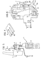
- a device according to the invention is generally indicated 1.
- This device includes a support casing 2 for fixing to the structure S ( Figure 1) of a domestic electrical appliance, near a loading or access opening O of the machine, which has an associated door P having a hook member A.
- the structure S of the machine Adjacent the opening O, the structure S of the machine has an aperture Q (Figure 1) for the passage and engagement of the hook member A when the door P is closed ( Figure 5).
- the aperture Q is big enough to allow the member A to be inserted and also to be rotated so as to be disengaged when the door P is opened ( Figure 12).
- the casing 2 of the device 1 has an aperture 3 facing the aperture Q ( Figure 1) for inserting the hook member A.
- a retaining member or slider 4 is slidably mounted inside the casing 2 of the device, with an aperture or window 5 corresponding substantially with the aperture 3 of the casing.
- the window 5 is engageable by the end of the hook element A when the door P is closed ( Figure 5).
- a spring 6 (Figure 3) is associated with the slider 4 in a manner known per se and tends to urge it into the position shown in Figures 1 and 2.
- an electromechanical control device 7 of a known type, is arranged inside the casing 2.
- This device 7 includes a bimetal strip 8, of configuration known per se, with one end securely fixed to the support casing 2 at 9. The other end of the bimetal strip bears a contact 10 facing a contact member 11 fixed to the casing 2.
- a resistive heating element 12 such as a positive-temperature coefficient (PTC) resistor, is associated with the bimetal strip 8 in a known manner.
- PTC positive-temperature coefficient
- the bimetal strip 8 assumes the configuration shown in Figure 3, in which it keeps the movable Contact 10 separate from the fixed contact 11 and the locking element 13 is in a rest position, withdrawn inside the casing 2.
- the bimetal strip 8 changes configuration, carrying the movable contact 10 into engagement with the contact 11 and tending to push the locking member 13 into an obstruction position in which it partially protrudes out of the casing 2 so as to cooperate functionally with the retaining slider 4 in a way which will be explained in detail later.
- the retaining slider 4 is mounted for movement relative to the support casing 2 between a rest position, shown in Figures 1, 2 and 12, 13, in which it allows the hook member A to engage the window 5 when the door P is closed and to disengage therefrom when the door is opened.
- the retaining slider 4 has a lateral projection 4a.
- the projection 4a contacts the end of the locking member 13.
- the retaining slider 4 is movable into a working position, shown in figures 5 and 6, in which is holds the hook member A in the condition closing the door P. In this position, the projection 4a of the slider 4 uncovers the locking member 13, as shown most clearly in Figure 6, enabling it to move into the projecting position under the control of the bimetal strip 8, when this latter is heated by the resistor 1 ( Figures 9 to 11).
- An unlocking device associated with the locking device 13, is generally indicated 15 in Figure 2.
- the unlocking device 15 includes a rocker 16 pivoted at 17 on the support casing about an axis substantially parallel to the direction of movement of the locking member 13.
- the rocker 16 has an arm 16a extending near the path of the locking member 13 and an opposite arm 16b.
- the end of the arm 16a of the rocker 16 extends beneath a resilient flap 18 fixed to the support casing.
- this flap (see Figure 4 in particular) has a plurality of slits 18a giving it the substantial appearance of a comb.
- the end of the arm 16a thereof slides against the flap 18 which offers some frictional resistance.
- the flap 18, which presses on the end of the said arm of the rocker, also helps to ensure that the rocker pivots only about the pivotal axis 17.
- an electrically-controlled actuator 19 is arranged in the casing 2 near the end of the arm 16b of the rocker 16.
- this actuator includes a solenoid 20 with a movable member 21, constituted at least in part of ferromagnetic material, mounted therein.
- the movable member 21 has a terminal pin 22 extending near to the end of the arm 16b of the rocker 16.
- the movable member 21-22 of the actuator device 19 is in the position shown in Figure 2 and the rocker 16 is positioned whereby the end of the arm 16a does not interfere with the path of movement of the locking device 13.
- the position of the rocker 16 is stabilised by the resilient flap 18.
- the top of the locking member 13 is bevelled to form an inclined plane 13a.
- the end of the arm 16a of the rocker 16 is correspondingly bevelled underneath to form an inclined plane 16c.
- the movable contact 10 carried by the strip 8 and the fixed contact 11 constitute together a switch arranged in series in an electric line supplying the domestic electrical appliance.
- the solenoid 20 of the actuator 19 can be connected to this electric line, downstream of the switch constituted by the contacts 10 and 11.
- a control unit (not illustrated) thereof causes current to flow to the resistor 12, thereby heating and commutating the bimetal strip 8 which thus changes to the configuration shown in Figure 7.
- the movable contact 10 is made to engage the fixed contact 11 and the locking member 13 is moved into its partially projecting position in which it prevents the slider 4 from resuming its rest position of Figure 1, by blocking the path of the projection 4a of the said slider 4. In this condition, the door P cannot be opened.
- the movable core 21-22 moves into the position shown in Figure 9, causing the rocker 16 to rotate.
- the end of the arm 16a of the rocker 16 engages the inclined plane 13a of the locking member 13 with its own inclined plane 16a, causing the locking member to return to its withdrawn position ( Figures 10 and 11).
- the solenoid 20 of the actuator device 19 can be activated by a control impulse from the control unit of the domestic appliance, as a result of the user pressing a control button to open the door P.
- the control unit only activates the said solenoid if the safety conditions for allowing the door P to be opened are fulfilled at that moment.
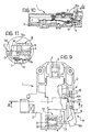
- the projection 4a of the slider 4 partially overlaps the locking member 13 before this latter is disengaged by the arm 16a of the rocker 16, whereby the slider 4 is able to continue on its path until it reaches its rest position ( Figures 12 to 14). Once it has reached this condition, the hook member A of the door P can be disengaged from the retaining slider 4, and the window Q, and the door P can be opened.
- the door P can be unlocked and opened during operation extremely quickly, without any annoying waiting time.
Description
- The present invention relates to a locking device for the door of a domestic electrical appliance.
- More specifically, the subject of the invention is a locking device which includes
- a support casing
- a retaining slider, mounted in the casing for movement between a working position in which it acts to retain a hook member secured to the door, and a rest position in which it allows the said member to disengage and the door to open, and
- an electromechanical control device which includes a bimetal strip with an associated resistive heating element, coupled to a movable locking device, movable, as a result of a heating of the strip, from a rest or release position to a locking position, in which the said locking. member is operable to prevent the slider from moving from the working position to the rest position.
-
- Such devices are currently used for washing machines or washer-dryers.
- Safety regulations demand that the door of a washing machine or washer-dryer cannot be opened in certain conditions, for example when the drum is moving and/or when the level of water in the washing compartment is over a predetermined spill level.
- In order to comply with these regulations, it has become routine to fit doors with locking devices which include electrically controlled actuators, such as solenoids or actuators with thermocouples and heating resistances. Such safety devices prevent the door from opening during a washing cycle and allow it to open at the end of the cycle, but often with a time lag of around 2-3 minutes after the cycle has ended.
- Some devices are made in such a way that if the door is closed when the machine is unplugged, it cannot be opened unless the machine is connected to the electricity supply. Such devices involve problems, for example when demonstrating the machines to the public in showrooms, where domestic appliances on display are not usually connected to the electricity supply.
- In order to overcome this problem, some washing machines have a system for manually unlocking the door, by means, for example, of a release cable accessible in the water intake compartment. This arrangement solves the problem of not being able to open the door with the machine unplugged, for example in a show room, but creates new safety problems since, by operating the release cable, the user could manage to open the door of the machine during a wash cycle.
- The object of the present invention is to provide a locking device for the door of a domestic electrical appliance that allows a user to open the door quickly, that is without having to wait, at any time he may want to, except during an operating cycle during which safety regulations demand that the door must not be able to be opened.
- This and other objects are achieved according to the invention by providing a locking device, the main characteristics of which are defined in the appended
Claim 1. - Further characteristics and advantages of the invention will become apparent from the detailed description which follows, provided purely by way of non-limitative example, with reference to the appended drawings, in which:
- Figure 1 is a partially sectioned view of a locking device of the invention, shown in the rest position, with the associated door open;
- Figure 2 is a partially sectioned view of the locking device of Figure 1, in the same rest condition;
- Figure 3 is a sectional view taken on the line III-III of Figure 2;
- Figure 4 is a partial perspective view of a braking member associated with a release-control member in a device of the invention;
- Figure 5 is a similar view to that of Figure 1 and shows the locking device in the rest condition, with the door of the domestic electrical appliance closed;
- Figure 6 is a similar view to that of Figure 2, showing the locking device in the same condition as Figure 5;
- Figure 7 is a view of a section taken on the line VII-VII of Figure 6;
- Figure 8 is a view on an enlarged scale of a detail indicated VIII in Figure 7;
- Figure 9 is a similar view to that of Figure 6, showing the locking device in a different operating condition;
- Figure 10 is a view of a section taken on the line X-X of Figure 9;
- Figure 11 is a view on an enlarged scale of a detail indicated XI in Figure 10;
- Figure 12 is a similar view to that of Figure 5, showing the locking device in the phase of opening the associated door;
- Figure 13 is a view in the direction of the arrow XIII of Figure 12, and
- Figure 14 is a view of a section taken on the line XIV-XIV of Figure 13.
-
- In the drawings, a device according to the invention is generally indicated 1. This device includes a
support casing 2 for fixing to the structure S (Figure 1) of a domestic electrical appliance, near a loading or access opening O of the machine, which has an associated door P having a hook member A. - Adjacent the opening O, the structure S of the machine has an aperture Q (Figure 1) for the passage and engagement of the hook member A when the door P is closed (Figure 5). In the embodiment illustrated, the aperture Q is big enough to allow the member A to be inserted and also to be rotated so as to be disengaged when the door P is opened (Figure 12).
- The
casing 2 of thedevice 1 has anaperture 3 facing the aperture Q (Figure 1) for inserting the hook member A. - A retaining member or
slider 4 is slidably mounted inside thecasing 2 of the device, with an aperture orwindow 5 corresponding substantially with theaperture 3 of the casing. - The
window 5 is engageable by the end of the hook element A when the door P is closed (Figure 5). - A spring 6 (Figure 3) is associated with the
slider 4 in a manner known per se and tends to urge it into the position shown in Figures 1 and 2. - As shown in Figure 3, an electromechanical control device 7, of a known type, is arranged inside the
casing 2. This device 7 includes a bimetal strip 8, of configuration known per se, with one end securely fixed to thesupport casing 2 at 9. The other end of the bimetal strip bears acontact 10 facing acontact member 11 fixed to thecasing 2. - A
resistive heating element 12, such as a positive-temperature coefficient (PTC) resistor, is associated with the bimetal strip 8 in a known manner. - The end of the bimetal strip 8 bearing the
contact 10 is engaged in a slot in alocking member 13 which is mounted for translation orthogonal to theretaining slider 4, through anaperture 14 in the casing 2 (see the enlarged details shown in Figures 8 and 11). - According to this arrangement, when the
resistor 12 is not supplied with current, and is thus "cold", the bimetal strip 8 assumes the configuration shown in Figure 3, in which it keeps themovable Contact 10 separate from thefixed contact 11 and thelocking element 13 is in a rest position, withdrawn inside thecasing 2. - When the
resistor 12 heats up, as a result of the passage of electricity, the bimetal strip 8 changes configuration, carrying themovable contact 10 into engagement with thecontact 11 and tending to push thelocking member 13 into an obstruction position in which it partially protrudes out of thecasing 2 so as to cooperate functionally with theretaining slider 4 in a way which will be explained in detail later. - The
retaining slider 4 is mounted for movement relative to thesupport casing 2 between a rest position, shown in Figures 1, 2 and 12, 13, in which it allows the hook member A to engage thewindow 5 when the door P is closed and to disengage therefrom when the door is opened. - As shown, for example, in Figure 2, the
retaining slider 4 has alateral projection 4a. When theslider 4 is in its rest position (Figures 1 and 3) theprojection 4a contacts the end of thelocking member 13. - The
retaining slider 4 is movable into a working position, shown in figures 5 and 6, in which is holds the hook member A in the condition closing the door P. In this position, theprojection 4a of theslider 4 uncovers thelocking member 13, as shown most clearly in Figure 6, enabling it to move into the projecting position under the control of the bimetal strip 8, when this latter is heated by the resistor 1 (Figures 9 to 11). - When the
locking member 13 is in its projecting position, it prevents theslider 4 from returning to its rest position from its working position. The door P thus cannot be opened. - An unlocking device, associated with the
locking device 13, is generally indicated 15 in Figure 2. - The
unlocking device 15 includes arocker 16 pivoted at 17 on the support casing about an axis substantially parallel to the direction of movement of thelocking member 13. Therocker 16 has anarm 16a extending near the path of thelocking member 13 and anopposite arm 16b. - The end of the
arm 16a of therocker 16 extends beneath aresilient flap 18 fixed to the support casing. In the embodiment illustrated by way of example, this flap (see Figure 4 in particular) has a plurality of slits 18a giving it the substantial appearance of a comb. During oscillation of therocker 16, the end of thearm 16a thereof slides against theflap 18 which offers some frictional resistance. Theflap 18, which presses on the end of the said arm of the rocker, also helps to ensure that the rocker pivots only about thepivotal axis 17. - With reference to Figure 2, an electrically-controlled
actuator 19 is arranged in thecasing 2 near the end of thearm 16b of therocker 16. In the embodiment illustrated, this actuator includes asolenoid 20 with amovable member 21, constituted at least in part of ferromagnetic material, mounted therein. Themovable member 21 has aterminal pin 22 extending near to the end of thearm 16b of therocker 16. - In the unexcited condition of the
solenoid 20, the movable member 21-22 of theactuator device 19 is in the position shown in Figure 2 and therocker 16 is positioned whereby the end of thearm 16a does not interfere with the path of movement of thelocking device 13. The position of therocker 16 is stabilised by theresilient flap 18. - When, as shown in Figure 9, the
retaining slider 4 is in its working position and current is passed through thesolenoid 20, the movable unit 21-22 translates and thepin 22 exerts a thrust on the end of thearm 16b of therocker 16, causing it to rotate so that thearm 16a interferes with thelocking member 13. - As shown, for example, in Figure 8, on the side facing the
arm 16a of therocker 16, the top of the lockingmember 13 is bevelled to form an inclined plane 13a. The end of thearm 16a of therocker 16 is correspondingly bevelled underneath to form an inclined plane 16c. - The
movable contact 10 carried by the strip 8 and the fixedcontact 11 constitute together a switch arranged in series in an electric line supplying the domestic electrical appliance. For convenience, thesolenoid 20 of theactuator 19 can be connected to this electric line, downstream of the switch constituted by thecontacts - The characteristics of the
locking device 1 described above will be better understood from the detailed description which follows of a complete operating cycle thereof. - When the door P of the machine is open (Figure 1), the retaining
slider 4 is in its rest position (Figures 1 and 2). No current passes through theresistor 12 and the bimetal strip 8 holds thecontacts member 13 in its withdrawn or rest position (Figures 2 and 3). Thesolenoid 20 is deactivated and therocker 16 is in the rest position (Figure 2). - When the door P is closed (Figure 5), the engagement of the hook member A in the
window 5 of the retainingslider 4 causes the latter to move into its working position (Figure 6). Theprojection 4a of theslider 4 uncovers thelocking device 13. However, until the domestic appliance is switched on, the lockingdevice 13 is held in its withdrawn or rest position by the bimetal strip 8, which is still in the configuration shown in Figure 3. - When the domestic electrical appliance is started, a control unit (not illustrated) thereof causes current to flow to the
resistor 12, thereby heating and commutating the bimetal strip 8 which thus changes to the configuration shown in Figure 7. As a result, as seen in Figures 7 and 8, themovable contact 10 is made to engage the fixedcontact 11 and the lockingmember 13 is moved into its partially projecting position in which it prevents theslider 4 from resuming its rest position of Figure 1, by blocking the path of theprojection 4a of the saidslider 4. In this condition, the door P cannot be opened. - If current passes through the
solenoid 20 of theactuator 19 in this condition, the movable core 21-22 moves into the position shown in Figure 9, causing therocker 16 to rotate. The end of thearm 16a of therocker 16 engages the inclined plane 13a of the lockingmember 13 with its owninclined plane 16a, causing the locking member to return to its withdrawn position (Figures 10 and 11). Thesolenoid 20 of theactuator device 19 can be activated by a control impulse from the control unit of the domestic appliance, as a result of the user pressing a control button to open the door P. On the other hand, the control unit only activates the said solenoid if the safety conditions for allowing the door P to be opened are fulfilled at that moment. - Still with reference to Figures 9 to 11, when the
rocker 16 rotates as a result of the activation of theactuator 19, the return of the lockingmember 13 to its withdrawn or inert position also results in opening of the switch constituted by thecontacts actuator 19 is almost instantaneously deactivated, and the movable core 21-22 returned to its initial position. Theslider 4 is then pushed by the spring 6 and can return to its rest position (Figure 2). While this is happening, theprojection 4a of the slider causes therocker 16 to return to its initial rest position. Furthermore, theprojection 4a of theslider 4 partially overlaps the lockingmember 13 before this latter is disengaged by thearm 16a of therocker 16, whereby theslider 4 is able to continue on its path until it reaches its rest position (Figures 12 to 14). Once it has reached this condition, the hook member A of the door P can be disengaged from the retainingslider 4, and the window Q, and the door P can be opened. - At this point, the device has resumed its initial condition.
- It will be appreciated that with the device of the invention the door P can be unlocked and opened during operation extremely quickly, without any annoying waiting time.
- It should also be noted that with the device described above it is possible to reopen the door P if the electricity supply is interrupted. In such a case, it is possible to unlock and open the door P as soon as the
resistor 12 has cooled sufficiently to allow the bimetal strip 8 to return the lockingmember 13 to the withdrawn condition in which it is possible to unlock the door. - The principle of the invention remaining unchanged, it is of course possible to vary embodiments and manufacturing details widely from those described and illustrated here, purely by way of non-limitative example, without departing thereby from the scope of the invention, as defined in the appended Claims.
Claims (9)
- A device (1) for locking the door (P) of a domestic appliance, which includescharacterised in that it also includes an unlocking device (15) which comprisesa support casing (2),a retaining slider (4) mounted in the casing (2) for movement between a working position in which it holds a hook member (A) secured to the door (P), and a rest position in which it allows the said hook member (A) to disengage so the door can be opened, andan electromechanical control device (7) which includes a bimetal strip (8) with an associated resistive heating element (12) and is coupled to a movable locking device (13), movable, as a result of the heating of the said strip (8), from a rest or release position into an obstruction position in which it prevents the retaining slider (4) from moving from its working to its rest position;a control member (16) mounted in the casing (2) for movement between a rest position in which it allows the said locking member (13) to move and a working position in which it acts to force the said locking member (13) to move from its obstruction position to its release position, andan electrically-controlled actuator (19) associated with the said unlocking device (15) which can be activated to cause the latter to move from its rest to its working position.
- A locking device according to Claim 1, characterised in that the said control member (16) is a rocker (16) pivoted to the said support casing (2) about an axis (17) substantially parallel to the direction of movement of the said locking member (13).
- A locking device according to Claim 2, characterised in that an arm (16a) of the said rocker (16) acts to interfere with the locking member (13) when the latter is in its obstruction position, and to cooperate with the said retaining slider (4, 4a) in such a way that the said rocker (16) can be pushed back into its rest position as a result of the movement of the said slider (4) into its rest position, following activation of the unlocking device (15).
- A device according to Claim 3, characterised in that a braking member (18) is associated with the said arm (16a) of the rocker (16) for resisting the oscillation thereof.
- A device according to Claim 4, characterised in that the said braking member is a resilient flap (18) fixed to the support casing (2) in such a way that the said arm (16a) of the rocker (16) slides against it.
- A device according to Claim 5, characterised in that the said resilient flap (18) has a plurality of slits (18a) giving it substantially the appearance of a comb.
- A device according to any one of the preceding Claims, characterised in that cooperating surfaces of the locking member (13) and of the control member (16) have respective planes (13a; 16c) inclined to the plane of movement of the said control member (16).
- A device according to any one of the preceding Claims, characterised in that the said actuator (19) includes a solenoid (20) with an associated movable member (21, 22) for co-operation with the said control member (16) of the unlocking device (15).
- A device according to Claim 8, in which a movable contact (10) is associated with the said bimetal strip (8) for cooperation with a contact (11) fixed to the casing (2) for closing an electricity supply line only when the locking member (13) is in its said obstruction position;
characterised in that the said solenoid (20) is connected to the said supply line downstream of the said contacts (10, 11).
Applications Claiming Priority (2)
| Application Number | Priority Date | Filing Date | Title |
|---|---|---|---|
| IT98TO000511A ITTO980511A1 (en) | 1998-06-11 | 1998-06-11 | DEVICE FOR LOCKING A DOOR OF A DOMESTIC APPLIANCE. |
| ITTO980511 | 1998-06-11 |
Publications (2)
| Publication Number | Publication Date |
|---|---|
| EP0965677A1 EP0965677A1 (en) | 1999-12-22 |
| EP0965677B1 true EP0965677B1 (en) | 2003-04-09 |
Family
ID=11416840
Family Applications (1)
| Application Number | Title | Priority Date | Filing Date |
|---|---|---|---|
| EP99111297A Expired - Fee Related EP0965677B1 (en) | 1998-06-11 | 1999-06-10 | A door locking device for an electric household appliance |
Country Status (3)
| Country | Link |
|---|---|
| EP (1) | EP0965677B1 (en) |
| DE (1) | DE69906623T2 (en) |
| IT (1) | ITTO980511A1 (en) |
Families Citing this family (14)
| Publication number | Priority date | Publication date | Assignee | Title |
|---|---|---|---|---|
| IT1320477B1 (en) * | 2000-06-30 | 2003-11-26 | Bitron Spa | DOOR LOCKING DEVICE, ESPECIALLY FOR A HOUSEHOLD APPLIANCE. |
| DE10038376C2 (en) | 2000-08-07 | 2003-04-30 | Zangenstein Elektro | Door lock for the door of an electrical household appliance |
| DE50009661D1 (en) | 2000-12-22 | 2005-04-07 | Zangenstein Elektro | Device for locking and releasing a door lock of an electrical device |
| ITTO20030273A1 (en) * | 2003-04-09 | 2004-10-10 | Bitron Spa | DOOR LOCKING AND UNLOCKING DEVICE |
| ITTO20031021A1 (en) * | 2003-12-18 | 2005-06-19 | Bitron Spa | SAFETY LOCK-DOOR DEVICE INCREASED, PARTICULARLY FOR APPLIANCES. |
| WO2006004317A1 (en) * | 2004-05-20 | 2006-01-12 | Lg Electronics Inc. | Door locking switch of washing machine and method thereof |
| DE602004004099T2 (en) * | 2004-07-13 | 2007-08-09 | C.R.F. S.C.P.A. | Machine for washing and / or drying laundry, with an electrically operable locking / unlocking device of the door |
| ITTO20050473A1 (en) * | 2005-07-08 | 2007-01-09 | Bitron Spa | HOLDING DEVICE, PARTICULARLY FOR A DOOR OF A HOUSEHOLD APPLIANCE |
| ITTO20070295A1 (en) * | 2007-05-03 | 2008-11-04 | Bitron Spa | DOOR-LOCK SYSTEM FOR A HOUSEHOLD APPLIANCE |
| PL2090690T3 (en) * | 2008-02-18 | 2011-09-30 | Electrolux Home Products Corp Nv | Door lock device with thermal protection and method for thermal protection of a door lock device in a household appliance |
| DE102008030902A1 (en) | 2008-06-30 | 2009-12-31 | BSH Bosch und Siemens Hausgeräte GmbH | Door closure device for a domestic appliance, door arrangement with a door closing device and method for closing a door of a domestic appliance |
| IT1400623B1 (en) | 2010-06-18 | 2013-06-14 | Eltek Spa | DOOR LOCK DEVICE FOR APPLIANCES WITH THERMAL ACTUATOR. |
| ITTO20110569A1 (en) * | 2011-06-29 | 2012-12-30 | Bitron Spa | LOCKING AND UNLOCKING DEVICE OF THE DOOR OF A HOUSEHOLD APPLIANCE |
| DE102012203484A1 (en) * | 2012-03-06 | 2013-09-12 | BSH Bosch und Siemens Hausgeräte GmbH | household appliance |
Citations (1)
| Publication number | Priority date | Publication date | Assignee | Title |
|---|---|---|---|---|
| DE2708086A1 (en) * | 1976-03-18 | 1977-09-22 | Texas Instruments Italia Spa | Door interlock with heating element - partic. for washing machines, includes electrically resistant plate |
Family Cites Families (4)
| Publication number | Priority date | Publication date | Assignee | Title |
|---|---|---|---|---|
| IT1162081B (en) * | 1978-02-24 | 1987-03-18 | Omp Off Meccano Plast | DOOR LOCKING DEVICE, IN PARTICULAR FOR DOMESTIC AND SIMILAR WASHING MACHINES |
| DE3430414A1 (en) * | 1984-08-18 | 1986-02-27 | Ellenberger & Poensgen Gmbh, 8503 Altdorf | DOOR LOCKING DEVICE WITH IMMEDIATE LOCKING AND DELAYED UNLOCKING WITH WATER LEVEL MONITORING |
| SE461989B (en) * | 1988-09-16 | 1990-04-23 | Electrolux Ab | LOADING MACHINE FOR A CLOSER TO A WASHER, CENTRIFUG |
| IT1250393B (en) * | 1991-06-13 | 1995-04-07 | Zanussi Elettrodomestici | DOOR LOCKING DEVICE FOR WASHING MACHINES OR LINEN DRYERS. |
-
1998
- 1998-06-11 IT IT98TO000511A patent/ITTO980511A1/en unknown
-
1999
- 1999-06-10 DE DE69906623T patent/DE69906623T2/en not_active Expired - Fee Related
- 1999-06-10 EP EP99111297A patent/EP0965677B1/en not_active Expired - Fee Related
Patent Citations (1)
| Publication number | Priority date | Publication date | Assignee | Title |
|---|---|---|---|---|
| DE2708086A1 (en) * | 1976-03-18 | 1977-09-22 | Texas Instruments Italia Spa | Door interlock with heating element - partic. for washing machines, includes electrically resistant plate |
Also Published As
| Publication number | Publication date |
|---|---|
| ITTO980511A1 (en) | 1999-12-13 |
| DE69906623D1 (en) | 2003-05-15 |
| EP0965677A1 (en) | 1999-12-22 |
| DE69906623T2 (en) | 2004-02-12 |
Similar Documents
| Publication | Publication Date | Title |
|---|---|---|
| EP0965677B1 (en) | A door locking device for an electric household appliance | |
| KR100681570B1 (en) | Unit having a memory metal actuator for latching devices of household appliances | |
| EP1619287B1 (en) | Household appliance, namely a machine for washing and/or drying laundry, with a door block/release device that can be actuated electrically | |
| US6634684B2 (en) | Latching mechanism for the door of an electric household appliance | |
| CN109252765B (en) | Pull-up limit gate latch with locking mechanism | |
| US4623179A (en) | Door latch for appliance | |
| KR100923146B1 (en) | Door lock for a door of a household appliance | |
| US6886868B2 (en) | Door-locking assembly | |
| US6840553B2 (en) | Apparatus for blocking and releasing a door lock of an electrical appliance | |
| EP1640493B1 (en) | Door-lock device for a household appliance | |
| AU2016257610B2 (en) | Locking device for a door of a domestic appliance | |
| US20080256999A1 (en) | Appliance latch with power failure unlock | |
| CA1235780A (en) | Control system for an access door | |
| EP0533635B1 (en) | A device for opening the port-hole door of a domestic washing machine | |
| US6336541B1 (en) | Actuation device having improved working speed | |
| EP2564000B1 (en) | Appliance latch with improved door retention at elevated temperatures | |
| KR100883413B1 (en) | Door lock and door lock switch for washing machine | |
| EP0439849B1 (en) | Device for rapid locking and delayed unlocking a door, more particularly of a washing machine | |
| EP0518147B1 (en) | Door interlock device for clothes washing and/or drying machines | |
| EP1861535B1 (en) | Blocking device for the door of an electric household appliance, in particular the door of a washing machine | |
| US4072867A (en) | Motor energized latch mechanism | |
| GB2031053A (en) | Improvements in or Relating to Interlock Mechanism | |
| EP0381022A1 (en) | A door locking means for a washing and/or drying machine for laundry | |
| GB2162240A (en) | Delayed-release door lock | |
| GB2047966A (en) | Washing machine with safety device |
Legal Events
| Date | Code | Title | Description |
|---|---|---|---|
| PUAI | Public reference made under article 153(3) epc to a published international application that has entered the european phase |
Free format text: ORIGINAL CODE: 0009012 |
|
| AK | Designated contracting states |
Kind code of ref document: A1 Designated state(s): DE ES FR GB |
|
| AX | Request for extension of the european patent |
Free format text: AL;LT;LV;MK;RO;SI |
|
| 17P | Request for examination filed |
Effective date: 20000608 |
|
| AKX | Designation fees paid |
Free format text: DE ES FR GB |
|
| GRAH | Despatch of communication of intention to grant a patent |
Free format text: ORIGINAL CODE: EPIDOS IGRA |
|
| GRAH | Despatch of communication of intention to grant a patent |
Free format text: ORIGINAL CODE: EPIDOS IGRA |
|
| GRAA | (expected) grant |
Free format text: ORIGINAL CODE: 0009210 |
|
| AK | Designated contracting states |
Designated state(s): DE ES FR GB |
|
| PG25 | Lapsed in a contracting state [announced via postgrant information from national office to epo] |
Ref country code: FR Free format text: LAPSE BECAUSE OF FAILURE TO SUBMIT A TRANSLATION OF THE DESCRIPTION OR TO PAY THE FEE WITHIN THE PRESCRIBED TIME-LIMIT Effective date: 20030409 |
|
| REG | Reference to a national code |
Ref country code: GB Ref legal event code: FG4D |
|
| PG25 | Lapsed in a contracting state [announced via postgrant information from national office to epo] |
Ref country code: ES Free format text: LAPSE BECAUSE OF FAILURE TO SUBMIT A TRANSLATION OF THE DESCRIPTION OR TO PAY THE FEE WITHIN THE PRESCRIBED TIME-LIMIT Effective date: 20031030 |
|
| PLBE | No opposition filed within time limit |
Free format text: ORIGINAL CODE: 0009261 |
|
| STAA | Information on the status of an ep patent application or granted ep patent |
Free format text: STATUS: NO OPPOSITION FILED WITHIN TIME LIMIT |
|
| EN | Fr: translation not filed | ||
| 26N | No opposition filed |
Effective date: 20040112 |
|
| PGFP | Annual fee paid to national office [announced via postgrant information from national office to epo] |
Ref country code: GB Payment date: 20050516 Year of fee payment: 7 |
|
| PGFP | Annual fee paid to national office [announced via postgrant information from national office to epo] |
Ref country code: DE Payment date: 20050520 Year of fee payment: 7 |
|
| PG25 | Lapsed in a contracting state [announced via postgrant information from national office to epo] |
Ref country code: GB Free format text: LAPSE BECAUSE OF NON-PAYMENT OF DUE FEES Effective date: 20060610 |
|
| PG25 | Lapsed in a contracting state [announced via postgrant information from national office to epo] |
Ref country code: DE Free format text: LAPSE BECAUSE OF NON-PAYMENT OF DUE FEES Effective date: 20070103 |
|
| GBPC | Gb: european patent ceased through non-payment of renewal fee |
Effective date: 20060610 |