EP0359671A1 - Equipment for raising and stacking or unstacking glass panes - Google Patents
Equipment for raising and stacking or unstacking glass panes Download PDFInfo
- Publication number
- EP0359671A1 EP0359671A1 EP89402531A EP89402531A EP0359671A1 EP 0359671 A1 EP0359671 A1 EP 0359671A1 EP 89402531 A EP89402531 A EP 89402531A EP 89402531 A EP89402531 A EP 89402531A EP 0359671 A1 EP0359671 A1 EP 0359671A1
- Authority
- EP
- European Patent Office
- Prior art keywords
- arm
- conveyor
- plates
- secondary conveyor
- axis
- Prior art date
- Legal status (The legal status is an assumption and is not a legal conclusion. Google has not performed a legal analysis and makes no representation as to the accuracy of the status listed.)
- Granted
Links
Images


Classifications
-
- B—PERFORMING OPERATIONS; TRANSPORTING
- B65—CONVEYING; PACKING; STORING; HANDLING THIN OR FILAMENTARY MATERIAL
- B65G—TRANSPORT OR STORAGE DEVICES, e.g. CONVEYORS FOR LOADING OR TIPPING, SHOP CONVEYOR SYSTEMS OR PNEUMATIC TUBE CONVEYORS
- B65G49/00—Conveying systems characterised by their application for specified purposes not otherwise provided for
- B65G49/05—Conveying systems characterised by their application for specified purposes not otherwise provided for for fragile or damageable materials or articles
- B65G49/06—Conveying systems characterised by their application for specified purposes not otherwise provided for for fragile or damageable materials or articles for fragile sheets, e.g. glass
- B65G49/068—Stacking or destacking devices; Means for preventing damage to stacked sheets, e.g. spaces
-
- B—PERFORMING OPERATIONS; TRANSPORTING
- B65—CONVEYING; PACKING; STORING; HANDLING THIN OR FILAMENTARY MATERIAL
- B65G—TRANSPORT OR STORAGE DEVICES, e.g. CONVEYORS FOR LOADING OR TIPPING, SHOP CONVEYOR SYSTEMS OR PNEUMATIC TUBE CONVEYORS
- B65G2249/00—Aspects relating to conveying systems for the manufacture of fragile sheets
- B65G2249/04—Arrangements of vacuum systems or suction cups
- B65G2249/045—Details of suction cups suction cups
Landscapes
- Sheets, Magazines, And Separation Thereof (AREA)
- Specific Conveyance Elements (AREA)
- Manipulator (AREA)
- Load-Engaging Elements For Cranes (AREA)
- Stackable Containers (AREA)
- Stacking Of Articles And Auxiliary Devices (AREA)
- Pallets (AREA)
- Re-Forming, After-Treatment, Cutting And Transporting Of Glass Products (AREA)
Abstract
Description
L'invention concerne un installation pour le relevage de plaques de verre, cette opération consistant à amener une plaque saisie dans une position sensiblement horizontale à une position sensiblement verticale, où elle est déposée, ce, afin de former des piles (empilage) ou bien à amener une plaque saisie dans une position sensiblement verticale sur une pile à une position sensiblement horizontale sur un convoyeur (désempilage).The invention relates to an installation for lifting glass plates, this operation consisting in bringing a gripped plate in a substantially horizontal position to a substantially vertical position, where it is deposited, in order to form piles (stacking) or else bringing a gripped plate in a substantially vertical position on a stack to a substantially horizontal position on a conveyor (destacking).
Dans les unités de production, le verre est obtenu sous forme d'une bande (par le procédé "float glass" par exemple) qui est ensuite découpée en plaques.In the production units, the glass is obtained in the form of a strip (by the "float glass" process for example) which is then cut into plates.
La bande et les plaques sont véhiculées par un (ou plusieurs) convoyeur principal horizontal.The belt and the plates are conveyed by one (or more) horizontal main conveyor.
Ces plaques sont ensuite relevées à un poste dit de préhension pour être empilées sur des chariots de manutention munis de pupitres (comportant un plan sensiblement horizontal et un plan sensiblement vertical) sur lesquels elles viennent en appui.These plates are then raised at a so-called gripping station to be stacked on handling trolleys provided with desks (comprising a substantially horizontal plane and a substantially vertical plane) on which they come to bear.
La bande de verre étant directement découpée sur le convoyeur principal dans le sens longitudinal (sens de l'axe du convoyeur) et le sens transversal (sens perpendiculaire au sens longitudinal dans le plan du convoyeur), le débit en objets augmente et les machines de relevage doivent fonctionner à des cadences rapides (2 à 4 s) ou très rapides (de l'ordre de 2 s).Since the glass strip is directly cut on the main conveyor in the longitudinal direction (direction of the conveyor axis) and the transverse direction (direction perpendicular to the longitudinal direction in the plane of the conveyor), the flow of objects increases and the machines lifting must operate at fast (2 to 4 s) or very fast (around 2 s) rates.
Le brevet français FR 86 05 656 publié sous le numéro 2 597 453 décrit une releveuse (machine de relevage) rapide compacte, dans laquelle des cadences de 2 à 4 s sont obtenues par multiplication du nombre de bras de préhension. Ainsi, dans cette releveuse selon l'art antérieur, il existe deux bras de préhension rétractables munis à chacune de leurs extrémités de moyens de préhension (ventouses), ce qui fait au total quatre points de préhension dont deux simultanément actifs (un par bras).French patent FR 86 05 656 published under the number 2,597,453 describes a compact rapid lifting device in which rates of 2 to 4 seconds are obtained by multiplying the number of gripping arms. Thus, in this lifter according to the prior art, there are two retractable gripping arms provided at each of their ends with gripping means (suction cups), which makes a total of four gripping points, two of which are simultaneously active (one per arm) .
La présente invention propose une installation avec une releveuse plus rapide et de conception différente.The present invention provides an installation with a faster lifter and a different design.
Plus précisément, l'installation comporte pour l'empilage :
- un convoyeur secondaire placé dans le prolongement du convoyeur principal et sur lequel sont saisies les plaques à un poste de préhension,
- en bout et au-dessous dudit convoyeur secondaire, une releveuse comportant :
. au moins un bras comportant un support sur lequel sont fixées des ventouses reliées à un moyen de dépression et disposées de façon à passer entre les rouleaux du convoyeur secondaire pour saisir la plaque,
. un système de bielle-manivelle actionné par au moins un vérin moteur agissant sur le(s)dit(s) bras pour obtenir sa (leur) rotation d'un angle d'environ 90° autour d'un axe horizontal perpendiculaire à l'axe du convoyeur de façon à amener les plaques au poste de dépose,
- un pupitre constituant le poste de dépose déplaçable selon l'axe du convoyeur,
- des moyens pour la commande automatique notamment des vitesses de convoyage, de l'arrêt des plaques, des mouvements du (des) bras et du pupitre,
ladite installation comportant en outre de façon caractéristique :
- au moins un vérin hydraulique équilibreur lié audit système bielle-manivelle et relié également à un accumulateur à azote de façon à amortir les mouvements du (des) bras et réduire la puissance énergétique installée,
- des moyens pour déplacer le(les) bras et/ou le support portant les ventouses selon l'axe longitudinal dudit (desdits) bras, pour la préhension et la dépose des plaques,
- des moyens pour déplacer latéralement le convoyeur secondaire d'une part et la releveuse d'autre part.More specifically, the installation comprises for stacking:
- a secondary conveyor placed in the extension of the main conveyor and on which the plates are gripped at a gripping station,
- at the end and below said secondary conveyor, a lifter comprising:
. at least one arm comprising a support on which suction cups are fixed connected to a vacuum means and arranged so as to pass between the rollers of the secondary conveyor to grip the plate,
. a rod-crank system actuated by at least one motor actuator acting on said arm (s) to obtain its (their) rotation by an angle of approximately 90 ° around a horizontal axis perpendicular to the axis of the conveyor so as to bring the plates to the depositing station,
- a console constituting the depositing station movable along the axis of the conveyor,
means for automatic control, in particular conveying speeds, stopping of the plates, movements of the arm (s) and of the console,
said installation further comprising typically:
- at least one hydraulic balancing cylinder linked to said rod-crank system and also connected to a nitrogen accumulator so as to dampen the movements of the arm (s) and reduce the installed energy power,
means for moving the arm (s) and / or the support carrying the suction cups along the longitudinal axis of said arm (s), for gripping and removing the plates,
- Means for laterally moving the secondary conveyor on the one hand and the lifter on the other.
L'installation comporte pour le désempilage :
- un convoyeur secondaire, placé dans le prolongement du convoyeur principal et sur lequel sont déposées les plaques à un poste de dépose,
- en bout et au-dessous dudit convoyeur secondaire, une releveuse comportant :
. au moins un bras comportant un support sur lequel sont fixés des ventouses reliées à un moyen de dépression et disposées de façon à passer entre les rouleaux du convoyeur secondaire pour déposer la plaque,
. un système bielle-manivelle actionné par au moins un vérin moteur agissant sur le(s)dit(s) bras pour obtenir sa (leur) rotation d'un angle d'environ 90° autour d'un axe horizontal perpendiculaire à l'axe du convoyeur de façon à amener les plaques au poste de dépose,
- un pupitre constituant le poste de préhension déplaçable selon l'axe du convoyeur,
- des moyens pour la commande automatique notamment des vitesses de convoyage, de l'arrêt des plaques, des mouvements du (des) bras et du pupitre,
ladite installation comportant en outre de façon caractéristique :
- au moins un vérin hydraulique équilibreur lié audit système bielle-manivelle et relié également à un accumulateur à azote de façon à amortir les mouvements du (des) bras et réduire la puissance énergétique installée,
- des moyens pour déplacer le (les) bras et/ou le support portant les ventouses selon l'axe longitudinal dudit (desdits) bras, pour la préhension et la dépose des plaques,
- des moyens pour déplacer latéralement le convoyeur secondaire d'une part et la releveuse d'autre part.The installation includes for destacking:
- a secondary conveyor, placed in the extension of the main conveyor and on which the plates are deposited at a deposition station,
- at the end and below said secondary conveyor, a lifter comprising:
. at least one arm comprising a support on which suction cups are attached connected to a vacuum means and arranged so as to pass between the rollers of the secondary conveyor to deposit the plate,
. a rod-crank system actuated by at least one motor cylinder acting on said arm (s) to obtain its (their) rotation by an angle of approximately 90 ° around a horizontal axis perpendicular to the axis of the conveyor so as to bring the plates to the depositing station,
- a console constituting the gripping station movable along the axis of the conveyor,
means for automatic control, in particular conveying speeds, stopping of the plates, movements of the arm (s) and of the console,
said installation further comprising typically:
- at least one hydraulic balancing cylinder linked to said rod-crank system and also connected to a nitrogen accumulator so as to dampen the movements of the arm (s) and reduce the installed energy power,
means for moving the arm (s) and / or the support carrying the suction cups along the longitudinal axis of said arm (s), for gripping and removing the plates,
- Means for laterally moving the secondary conveyor on the one hand and the lifter on the other.
Selon une autre caractéristique de l'invention, le déplacement sur le vérin moteur est commandé de façon à ce que la rotation du bras obéisse à la loi :
A,B,C = constantes numériquesAccording to another characteristic of the invention, the movement on the motor cylinder is controlled so that the rotation of the arm obeys the law:
A, B, C = numerical constants
La description sera mieux suivie à partir des figures :
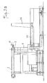
- - la figure 1 représente une vue de l'installation dans l'axe du convoyeur secondaire ;
- - les figures 2A et 2B sont des vues latérales (perpendiculaires à l'axe du convoyeur) ;
- - la figure 3 présente en coupe latérale le bras avec le support et les ventouses ;
- - les figures 4 et 5 montrent mieux le système bielle-manivelle pour l'entraînement du bras ;
- - et les figures 5 et 6 montrent l'accumulateur à azote.
- - Figure 1 shows a view of the installation in the axis of the secondary conveyor;
- - Figures 2A and 2B are side views (perpendicular to the axis of the conveyor);
- - Figure 3 shows in side section the arm with the support and the suction cups;
- - Figures 4 and 5 better show the connecting rod-crank system for driving the arm;
- - And Figures 5 and 6 show the nitrogen accumulator.
Les plaques de verre défilent sur une ligne de convoyage. Pour être relevées, elles sont dérivées sur un ou des épis qui sont des convoyeurs disposés perpendiculairement à la ligne de convoyage principale, elles sont relevées alors par des machines de relevage situées en bout d'épi. On appellera convoyeur principal, le convoyeur véhiculant les plaques pour les amener à l'installation de relevage.The glass plates parade on a conveyor line. To be raised, they are derived on one or more ears which are conveyors arranged perpendicular to the main conveyor line, they are then raised by lifting machines located at the end of the ear. The main conveyor will be called the conveyor conveying the plates to bring them to the lifting installation.
Cette installation selon l'invention comporte un convoyeur secondaire de longueur réduite (de l'ordre de 1 à 2 m par exemple) qui est placé dans le prolongement du convoyeur principal.This installation according to the invention comprises a secondary conveyor of reduced length (of the order of 1 to 2 m for example) which is placed in the extension of the main conveyor.
Sur les figures 1, 2A et 2B, le convoyeur secondaire est repéréen (1), il est muni de rouleaux (2) sur lesquels s'appuie la plaque (3). La plaque arrive ainsi en bout du convoyeur secondaire (1), elle s'arrête devant la releveuse à un poste dit de préhension.In FIGS. 1, 2A and 2B, the secondary conveyor is identified (1), it is provided with rollers (2) on which the plate (3) rests. The plate thus arrives at the end of the secondary conveyor (1), it stops in front of the lifter at a so-called gripping station.
Selon un mode de fonctionnement préféré, le convoyeur secondaire a une vitesse inférieure à celle du convoyeur principal, elle devient nulle lorsque la plaque est au poste de préhension.According to a preferred operating mode, the secondary conveyor has a speed lower than that of the main conveyor, it becomes zero when the plate is at the gripping station.
Une plaque passe du convoyeur principal au convoyeur secondaire lorsque la plaque précédente a été saisie. Le nombre des épis est alors déterminé par l'homme du métier en fonction des cadences de relevage, des vitesses de convoyeur et des longueurs des plaques.A plate moves from the main conveyor to the secondary conveyor when the previous plate has been entered. The number of ears is then determined by a person skilled in the art as a function of lifting rates, conveyor speeds and lengths of the plates.
Au poste de préhension, les plaques consécutives de mêmes dimensions à relever se trouvent dans la même position.
- elles sont en appui contre des butées (4) disposées en bout du convoyeur secondaire ;
- dans une même campagne de production, les plaques à relever ont les mêmes dimension et on constate que leurs bords latéraux sont pratiquement alignés pendant un certain temps (le dévirage, c'est-à-dire le décalage, étant de l'ordre de 10 mm sur 3 heures) ;At the gripping station, the consecutive plates of the same dimensions to be raised are in the same position.
- They are in abutment against stops (4) arranged at the end of the secondary conveyor;
- in the same production campaign, the plates to be lifted have the same dimensions and it can be seen that their lateral edges are practically aligned for a certain time (the unscrewing, that is to say the offset, being of the order of 10 mm over 3 hours);
On a donc, pendant le temps de formation d'une pile, des plaques ayant toujours la même position au niveau de leur bord inférieur (celui qui viendra en appui sur la surface quasi horizontale du pupitre) et de leurs bords latéraux.There are therefore, during the time of formation of a stack, plates always having the same position at their lower edge (the one which will come to bear on the almost horizontal surface of the desk) and their lateral edges.
L'installation de relevage selon l'invention comporte également une releveuse placée au-dessous et en bout du convoyeur secondaire.The lifting installation according to the invention also comprises a lifting device placed below and at the end of the secondary conveyor.
Elle comporte au moins un bras (5) comportant un support (8) sur lequel sont fixées des ventouses (7).It comprises at least one arm (5) comprising a support (8) on which suction cups (7) are fixed.
Selon le mode de réalisation figure 1, elle a un seul bras (5) terminé par deux doigts (6) porteurs chacun d'une ventouse (7), les doigts étant portés par un support (8).According to the embodiment of Figure 1, it has a single arm (5) terminated by two fingers (6) each carrying a suction cup (7), the fingers being carried by a support (8).
Si la largeur du convoyeur secondaire est importante, on peut prévoir plusieurs bras, par exemple deux, montés côte à côte.If the width of the secondary conveyor is large, it is possible to provide several arms, for example two, mounted side by side.
Le nombre de bras, de ventouses et la largeur du support sont déterminés par l'homme du métier en fonction des dimensions des plaques à relever.The number of arms, suction cups and the width of the support are determined by a person skilled in the art according to the dimensions of the plates to be lifted.
Les doigts (6) ont une longueur suffisante pour permettre le passage des ventouses entre les rouleaux (2).The fingers (6) have a sufficient length to allow the passage of the suction cups between the rollers (2).
Pour que les plaques soient en équilibre lors du relevage, il est nécessaire :
- qu'elles soient placées de façon à ce que les ventouses soient disposées symétriquement de part et d'autre de l'axe longitudinal de symétrie des plaques à relever,
- et que la releveuse ou les butées (4) soient longitudinalement déplacées pour que les centres des ventouses soient proches de l'axe médian de la plaque (axe perpendiculaire à l'axe longitudinal et passant par le milieu de la plaque).In order for the plates to be balanced during lifting, it is necessary:
- they are placed so that the suction cups are arranged symmetrically on either side of the longitudinal axis of symmetry of the plates to be lifted,
- And that the lifter or the stops (4) are moved longitudinally so that the centers of the suction cups are close to the median axis of the plate (axis perpendicular to the longitudinal axis and passing through the middle of the plate).
Pour vérifier la première condition, avant chaque campagne (correspondant à des mêmes dimensions de plaques), la releveuse et/ou le convoyeur secondaire sont latéralement déplacés.To check the first condition, before each campaign (corresponding to the same plate dimensions), the lifter and / or the secondary conveyor are moved laterally.
Lorsque l'écartement entre les rouleaux du convoyeur secondaire permet juste le passage des doigts (6) (disposition avantageuse), le convoyeur secondaire et la releveuse doivent être déplacés simultanément. On peut utiliser par exemple (figure 1) un vérin (9) agissant sur un bâti 10 mobile latéralement (dans des rails par exemple), ledit bâti supportant le convoyeur secondaire et la releveuse, et ledit bâti étant également muni de moyens pour son immobilisation.When the spacing between the rollers of the secondary conveyor allows just the passage of the fingers (6) (advantageous arrangement), the secondary conveyor and the lifter must be moved simultaneously. One can use for example (Figure 1) a jack (9) acting on a
On remarque que l'écartement entre les doigts (6) dépend non seulement de l'écartement entre deux rouleaux consécutifs du convoyeur mais aussi dépend de la largeur (sens perpendiculaire à l'axe du convoyeur) des plaques et qu'on ne peut augmenter inconsidérément cet écartement. On ne peut également pas admettre que la plaque de verre déborde latéralement la ventouse de façon importante.Note that the spacing between the fingers (6) depends not only on the spacing between two consecutive rollers of the conveyor but also depends on the width (direction perpendicular to the axis of the conveyor) of the plates and that it cannot be increased inconsiderately this spacing. It can also not be admitted that the glass plate extends beyond the suction cup significantly.
De telles releveuses fonctionnent bien pour des plaques de verre appelées de petites dimensions dans l'industrie verrière, c'est-à-dire jusqu'à de l'ordre de 1,5 m en largeur et 1 m en longueur et les plaques au poste de préhension étant situées à plus de 25 mm du bord latéral du convoyeur.Such lifters work well for glass plates called small in the glass industry, that is to say up to about 1.5 m in width and 1 m in length and the plates at gripping station being located more than 25 mm from the lateral edge of the conveyor.
Le mode de réalisation figure 1 (un seul bras avec deux doigts et deux ventouses) est particulièrement bien adapté à cette application.The embodiment in FIG. 1 (a single arm with two fingers and two suction cups) is particularly well suited to this application.
L'homme du métier déterminera l'écartement entre les doigts et les rouleaux du convoyeur secondaire en fonction des plaques qu'il aura à traiter.A person skilled in the art will determine the spacing between the fingers and the rollers of the secondary conveyor as a function of the plates which he will have to treat.
Les ventouses sont de type connu, elles sont reliées à un système de mise en dépression grâce auquel un effet de succion est obtenu dans la ventouse et la plaque de verre est saisie. Pour lâcher la plaque, il suffit de couper le vide en se remettant à la pression atmosphérique.The suction cups are of known type, they are connected to a vacuum system by which a suction effect is obtained in the suction cup and the glass plate is gripped. To let go of the plate, simply cut the vacuum by returning to atmospheric pressure.
Chaque ventouse est montée sur un ressort qui lui permet de s'adapter aux plaques d'épaisseur différente.Each suction cup is mounted on a spring which allows it to adapt to plates of different thickness.
Pour éviter les butées (4) lors du relevage de la plaque, on dispose de deux solutions prises séparément ou en combinaison, consistant en :
Première solution : des moyens pour faire coulisser le support (8) le long du bras (5) (figure 3);
Deuxième solution : des moyens pour déplacer le bras (5) selon son axe longitudinal.To avoid the stops (4) when raising the plate, there are two solutions taken separately or in combination, consisting of:
First solution: means for sliding the support (8) along the arm (5) (Figure 3);
Second solution: means for moving the arm (5) along its longitudinal axis.
Dans la première solution, ce déplacement est obtenu par exemple au moyen d'un vérin (11) à petite course automatiquement commandé monté dans le bras (5) pour agir sur le support (8). Dans le mode de réalisation de la figure 3, la tige du vérin (9) est solidarisée à une languette (12) fixée au support (8). Ledit support entoure l'extrémité supérieure du bras (5) sur une certaine distance, de sorte que, même en position relevée (tige de vérin sortie), le support (8) coiffe encore le bras (5), ce afin d'éviter l'entrée de poussière (de verre notamment) dans le bras.In the first solution, this displacement is obtained for example by means of an actuator (11) with short stroke automatically controlled mounted in the arm (5) to act on the support (8). In the embodiment of Figure 3, the cylinder rod (9) is secured to a tongue (12) fixed to the support (8). Said support surrounds the upper end of the arm (5) over a certain distance, so that, even in the raised position (cylinder rod extended), the support (8) still covers the arm (5), in order to avoid the entry of dust (particularly glass) into the arm.
D'une façon générale, tous les moyens d'actionnement sont à l'intérieur du bras pour être protégés, seuls les moyens d'alimentation en énergie sont ou ont une sortie à l'extérieur (canalisations pour fluides par exemple).Generally, all the actuating means are inside the arm to be protected, only the energy supply means are or have an outlet outside (pipes for fluids for example).
Dans la deuxième solution, ce déplacement est obtenu par exemple au moyen d'un vérin avec un excentrique agissant sur l'extrémité du bras non porteuse de ventouses.In the second solution, this displacement is obtained for example by means of a jack with an eccentric acting on the end of the arm not carrying suction cups.
Dans ces deux solutions, le bras (5) et/ou le support (8) est relevé pour la saisie de la plaque, et il est ensuite ramené à sa position initiale pendant la rotation du bras, avant ou après dépose selon la position du poste de dépose.In these two solutions, the arm (5) and / or the support (8) is raised for gripping the plate, and it is then returned to its initial position during the rotation of the arm, before or after removal depending on the position of the drop-off station.
Pour des raisons de cadences, d'encombrement de la plaque en relevage, et de facilité de dépose, on préfère ramener à la position initiale pendant la rotation du bras avant dépose, puis à nouveau déplacer le support ou le bras pour la dépose, et enfin, le ramener à la position initiale pendant la rotation après dépose pour pouvoir prendre une nouvelle plaque déjà en position au poste de préhension.For reasons of speed, size of the lifting plate, and ease of removal, it is preferable to return to the initial position during the rotation of the arm before removal, then again move the support or the arm for removal, and finally, bring it back to the initial position during rotation after removal to be able to take a new plate already in position at the gripping station.
L'autre extrémité du bras (5) est entraînée en rotation entre la position correspondant au bras, au poste de préhension et celle correspondant au bras en position au poste de dépose (fig. A2).The other end of the arm (5) is rotated between the position corresponding to the arm, at the gripping station and that corresponding to the arm in position at the removal station (fig. A2).
Les plans du convoyeur et du pupitre étant sensiblement horizontaux, l'angle de rotation est légèrement supérieur à 90° (en général entre 90° et 95°).The planes of the conveyor and the console being substantially horizontal, the angle of rotation is slightly greater than 90 ° (in general between 90 ° and 95 °).
Selon l'invention, la rotation est obtenue au moyen d'un système bielle-manivelle (13) (fig. 4) monté sur un arbre d'entraînement (14) fixé au bras (5) par exemple par solidarisation aux pièces (5a) et (5b) représentées figures 3 et 5.According to the invention, the rotation is obtained by means of a rod-crank system (13) (fig. 4) mounted on a drive shaft (14) fixed to the arm (5) for example by securing to the parts (5a ) and (5b) shown in Figures 3 and 5.
Un vérin moteur (15) (de préférence hydraulique) solidaire du maneton (16) de la bielle (23) (figure 4) agit sur l'arbre d'entraînement (14) qui lui-même entraîne en rotation le bras (5). On peut également prévoir un second vérin moteur (15( solidaire du maneton (17) de la bielle (23), un vérin étant actif pour la descente de la plaque (rotation du bras dans un sens) et l'autre pour la remontée du bras (retour). Cette possibilité n'est pas représentée sur les figuresA motor cylinder (15) (preferably hydraulic) integral with the crank pin (16) of the connecting rod (23) (Figure 4) acts on the drive shaft (14) which itself rotates the arm (5) . It is also possible to provide a second motor cylinder (15 (integral with the crank pin (17) of the connecting rod (23), one cylinder being active for lowering the plate (rotation of the arm in one direction) and the other for raising the arm (back) This possibility is not shown in the figures
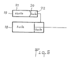
Selon l'invention, au moins un vérin hydraulique équilibreur (18) est monté sur le système bielle-manivelle (13).According to the invention, at least one hydraulic balancing cylinder (18) is mounted on the connecting rod-crank system (13).
Ce vérin (18) comporte un piston percé qui permet alors le passage de l'huile d'un compartiment d'un vérin à l'autre selon le mouvement de la tige du piston (fig. 6).This cylinder (18) has a pierced piston which then allows oil to pass from one compartment from one cylinder to the other according to the movement of the piston rod (fig. 6).
Le vérin (18) est également relié à un accumulateur à azote (19) constitué par un récipient muni d'une paroi mobile (20) le séparant en deux chambres, l'une (21) est fermée et contient l'azote, l'autre (22) est reliée au vérin (18).The jack (18) is also connected to a nitrogen accumulator (19) constituted by a container provided with a movable wall (20) separating it into two chambers, one (21) is closed and contains nitrogen, l 'other (22) is connected to the cylinder (18).
Un vérin équilibreur (18) est nécessairement monté sur le même maneton que le vérin moteur (15) de façon à ce que l'énergie accumulée lors de la descente du bras pour amener la plaque au poste de dépose soit restituée lors de la remontée dudit bras, cette énergie accumulée étant d'autant plus grande que la plaque qui descend devient motrice à partir d'un certain angle. Cette réalisation est représentée figure 4, le vérin (18) étant en traits pleins.A balancing cylinder (18) is necessarily mounted on the same crankpin as the motor cylinder (15) so that the energy accumulated during the descent of the arm to bring the plate to the deposition station is restored during the ascent of said arm, this accumulated energy being all the greater as the descending plate becomes motive from a certain angle. This embodiment is shown in Figure 4, the cylinder (18) being in solid lines.
Un second vérin (18) peut être ajouté, il est alors solidarisé au maneton (17) de la bielle (23). Sur la figure 4, cette disposition correspond au vérin (18) en pointillés.A second cylinder (18) can be added, it is then secured to the crank pin (17) of the connecting rod (23). In Figure 4, this arrangement corresponds to the cylinder (18) in dotted lines.
Le déplacement de la tige du vérin moteur (15) provoque également le coulissement de la tige du vérin équilibreur (18).The displacement of the rod of the driving cylinder (15) also causes the sliding of the rod of the balancing cylinder (18).
Le piston de ce vérin étant percé, l'huile communique d'une chambre à l'autre dans le vérin (15) et communique avec la chambre (22) de l'accumulateur.The piston of this jack being pierced, the oil communicates from one chamber to the other in the jack (15) and communicates with the chamber (22) of the accumulator.
Si on se réfère à la schématisation en traits pleins de la figure 4, lorsque le bras tourne pour amener la plaque du poste de préhension au poste de saisie, la tige du vérin (15) rentre, l'huile du vérin (18) chassée par la rentrée de la tige de ce vérin va fuir dans la chambre (22) de l'accumulateur. Au retour du bras, cette énergie est restituée : l'huile repart dans le vérin (18) provoquant la rentrée de son piston qui actionne alors la bielle (23), la rotation du bras (5) est obtenue pour des pressions des vérins moteur et équilibreur convenablement choisies par l'homme de métier.If we refer to the diagram in solid lines of Figure 4, when the arm turns to bring the plate from the gripping station to the gripping station, the cylinder rod (15) returns, the oil from the cylinder (18) expelled by the retraction of the rod of this jack will leak into the chamber (22) of the accumulator. When the arm returns, this energy is restored: the oil goes back into the cylinder (18) causing its piston to re-enter which then actuates the connecting rod (23), the rotation of the arm (5) is obtained for the pressures of the motor cylinders and balancer suitably chosen by the skilled person.
Ce dispositif avantageux permet l'amortissement des mouvements (rôle d'équilibreur) mais également de diminuer la puissance installée (rôle de récupérateur d'énergie).This advantageous device allows the damping of movements (role of balancer) but also to reduce the installed power (role of energy recuperator).
Les essais faits sur la machine ont pu montrer qu'il est particulièrement avantageux d'avoir pour la rotation du bras la loi de mouvement suivante :
A,B,C = constantes déterminées expérimentalement, de façon à optimiser les accélérations et décelérations du bras pour garantir les cadences et l'absence de chocs.Tests carried out on the machine have shown that it is particularly advantageous to have the following law of motion for the rotation of the arm:
A, B, C = constants determined experimentally, so as to optimize the acceleration and deceleration of the arm to guarantee the cadences and the absence of shocks.
Le vérin moteur est alors automatiquement commandé pour générer cette loi sur le bras.The motor cylinder is then automatically controlled to generate this law on the arm.
Le poste de dépose es constitué par un pupitre (24) possédant un plan sensiblement horizontal et un plan sensiblement vertical pour l'appui des plaques. Le pupitre est positionné lorsqu'il arrive vide de façon à être dans l'axe longitudinal des plaques et dans celui du bras.The depositing station is constituted by a desk (24) having a substantially horizontal plane and a substantially vertical plane for supporting the plates. The desk is positioned when it arrives empty so as to be in the longitudinal axis of the plates and in that of the arm.
Son plan horizontal est situé à une hauteur légèrement inférieure à celle du bord inférieur de la plaque qui arrive, la plaque lâchée par les ventouses chutant pour la dépose sur ledit plan.Its horizontal plane is situated at a height slightly lower than that of the lower edge of the plate which arrives, the plate dropped by the suction cups falling for deposit on said plane.
La hauteur de chute admissible est donnée par l'exploitant verrier en fonction du matériau et de l'épaisseur de la plaque.The admissible drop height is given by the glass operator depending on the material and the thickness of the plate.
Pour améliorer l'empilage des plaques, de l'air peut être soufflé par les ventouses pour plaquer le verre contre la pile existante.To improve the stacking of the plates, air can be blown through the suction cups to press the glass against the existing stack.
Après chaque dépose, le pupitre est déplacé pas à pas dans le sens de l'axe du convoyeur par exemple par un vérin (25), d'une valeur prédéterminée en fonction de l'épaisseur des plaques.After each removal, the console is moved step by step in the direction of the axis of the conveyor, for example by a jack (25), by a predetermined value depending on the thickness of the plates.
L'installation comporte également des moyens pour sa commande automatique à partir d'informations fournies notamment par des capteurs disposés sur l'installation traitées par un ordinateur muni d'un logiciel. Sont notamment réglés automatiquement les vitesses de convoyage, l'arrêt des plaques au poste de préhension, la rotation du bras, le déplacement pas à pas du pupitre, son évacuation et sa mise en place, les déplacements latéraux de la releveuse et du convoyeur secondaire. . .The installation also includes means for its automatic control from information provided in particular by sensors arranged on the installation processed by a computer provided with software. In particular, the conveyor speeds are automatically adjusted, the plates stop at the gripping station, the arm rotation, the step-by-step movement of the console, its evacuation and its positioning, the lateral movements of the lifter and the secondary conveyor. . . .
Une telle installation a permis le relevage très rapide (de l'ordre de 2 s et même moins de 2 s) de plaques de verre de :
L'invention a été décrite pour l'empilage de plaques de verre, elle est utilisable pour le désempilage de plaques de verre sans apporter de modifications mécaniques à l'installation, seules des modifications du logiciel de commande sont nécessaires.The invention has been described for stacking glass plates, it can be used for unstacking glass plates without making mechanical modifications to the installation, only modifications to the control software are necessary.
Il est alors évident pour l'homme de métier que :
- le poste de préhension est constitué par le pupitre (24),
le poste de dépose est constitué par le convoyeur principal qui peut alors défiler sans arrêt.It is then obvious to the skilled person that:
- the gripping station is constituted by the console (24),
the drop-off station is made up of the main conveyor, which can then scroll without stopping.
Claims (4)
- un convoyeur secondaire (1) placé dans le prolongement dudit convoyeur principal et sur lequel sont saisies les plaques (3) à un poste de préhension,
- en bout et au-dessous dudit convoyeur secondaire, une releveuse comportant :
. au moins un bras (5) comportant un support (8) sur lequel sont fixées des ventouses (7) reliées à un moyen de dépression et disposées de façon à passer entre les rouleaux (2) du convoyeur secondaire pour saisir la plaque,
. un système bielle-manivelle (13) actionné par au moins un vérin moteur (15) agissant sur le(s)dit(s) bras pour obtenir sa (leur) rotation d'un angle d'environ 90° autour d'un axe horizontal perpendiculaire à l'axe du convoyeur de façon à amener les plaques au poste de dépose,
- un pupitre (24) constituant le poste de dépose déplaçable selon l'axe du convoyeur,
- des moyens pour la commande automatique notamment des vitesses de convoyage, de l'arrêt des plaques, des mouvements du (des) bras et du pupitre,
caractérisée en ce qu'elle comporte en outre :
- au moins un vérin hydraulique équilibreur (18) lié audit système bielle-manivelle (13) et relié également à un accumulateur à azote (19) de façon à amortir les mouvements du (des) bras et réduire la puissance énergétique installée,
- des moyens pour déplacer le(les) bras (5) et/ou le support (8) portant les ventouses (7) selon l'axe longitudinal dudit(desdits) bras, pour la préhension et la dépose des plaques,
- des moyens pour déplacer latéralement le convoyeur secondaire d'une part et la releveuse d'autre part.1. Installation for the rapid lifting and stacking of moving glass plates on a horizontal main conveyor, comprising:
a secondary conveyor (1) placed in the extension of said main conveyor and on which the plates (3) are gripped at a gripping station,
- at the end and below said secondary conveyor, a lifter comprising:
. at least one arm (5) comprising a support (8) on which are fixed suction cups (7) connected to a vacuum means and arranged so as to pass between the rollers (2) of the secondary conveyor to grip the plate,
. a rod-crank system (13) actuated by at least one motor cylinder (15) acting on said arm (s) to obtain its (their) rotation by an angle of approximately 90 ° about an axis horizontal perpendicular to the axis of the conveyor so as to bring the plates to the depositing station,
- a console (24) constituting the depositing station movable along the axis of the conveyor,
means for automatic control, in particular conveying speeds, stopping of the plates, movements of the arm (s) and of the console,
characterized in that it further comprises:
- at least one hydraulic balancing cylinder (18) linked to said connecting rod-crank system (13) and also connected to a nitrogen accumulator (19) so as to dampen the movements of the arm (s) and reduce the installed energy power,
- means for moving the arm (s) (5) and / or the support (8) carrying the suction cups (7) along the longitudinal axis of said (said) arm, for gripping and removing the plates,
- Means for laterally moving the secondary conveyor on the one hand and the lifter on the other.
- un convoyeur secondaire (1), placé dans le prolongement du convoyeur principal et sur lequel sont déposées les plaques (3) à un poste de dépose,
- en bout et au-dessous dudit convoyeur secondaire, une releveuse comportant :
. au moins un bras (5) comportant un support (8) sur lequel sont fixés des ventouses (7) reliées à un moyen de dépression et disposées de façon à passer entre les rouleaux (2) du convoyeur secondaire pour déposer la plaque,
. un système bielle-manivelle (13) actionné par au moins un vérin moteur (15) agissant sur le(s)dit(s) bras pour obtenir sa (leur) rotation d'un angle d'environ 90° autour d'un axe horizontal perpendiculaire à l'axe du convoyeur de façon à amener les plaques au poste de dépose,
- un pupitre (24) constituant le poste de préhension déplaçable selon l'axe du convoyeur,
- des moyens pour la commande automatique notamment des vitesses de convoyage, de l'arrêt des plaques, des mouvements du (des) bras et du pupitre,
caractérisé en ce qu'elle comporte en outre
- au moins un vérin hydraulique équilibreur (18) lié audit système bielle-manivelle (13) et relié également à un accumulateur à azote (19) de façon à amortir les mouvements du (des) bras et réduire la puissance énergétique installée,
- des moyens pour déplacer le (les) bras (5) et/ou le support (8) portant les ventouses (7) selon l'axe longitudinal dudit (desdits) bras, pour la préhension et la dépose des plaques,
- des moyens pour déplacer latéralement le convoyeur secondaire d'une part et la releveuse d'autre part.2. Installation for the rapid lifting and destacking of glass plates comprising:
- a secondary conveyor (1), placed in the extension of the main conveyor and on which the plates (3) are deposited at a depositing station,
- at the end and below said secondary conveyor, a lifter comprising:
. at least one arm (5) comprising a support (8) on which are fixed suction cups (7) connected to a vacuum means and arranged so as to pass between the rollers (2) of the secondary conveyor to deposit the plate,
. a rod-crank system (13) actuated by at least one motor cylinder (15) acting on said arm (s) to obtain its (their) rotation by an angle of approximately 90 ° about an axis horizontal perpendicular to the axis of the conveyor so as to bring the plates to the depositing station,
- a console (24) constituting the gripping station movable along the axis of the conveyor,
means for automatic control, in particular conveying speeds, stopping of the plates, movements of the arm (s) and of the console,
characterized in that it further comprises
- at least one hydraulic balancing cylinder (18) linked to said connecting rod-crank system (13) and also connected to a nitrogen accumulator (19) so as to dampen the movements of the arm (s) and reduce the installed energy power,
- means for moving the arm (s) (5) and / or the support (8) carrying the suction cups (7) along the longitudinal axis of said (said) arm, for gripping and removing the plates,
- Means for laterally moving the secondary conveyor on the one hand and the lifter on the other.

A,B,C = constantes.3. Installation according to one of claims 1 or 2, characterized in that the movement on the motor cylinder is controlled so that the rotation of the arm (s) obeys the law:
A, B, C = constants.
Priority Applications (1)
| Application Number | Priority Date | Filing Date | Title |
|---|---|---|---|
| AT89402531T ATE73414T1 (en) | 1988-09-15 | 1989-09-15 | DEVICE FOR LIFTING AND STACKING OR DISASSEMBLING A STACK OF GLASS PANES. |
Applications Claiming Priority (2)
| Application Number | Priority Date | Filing Date | Title |
|---|---|---|---|
| FR8812053A FR2636324A1 (en) | 1988-09-15 | 1988-09-15 | INSTALLATION FOR RAPID STACKING AND STACKING OF GLASS PLATES |
| FR8812053 | 1988-09-15 |
Publications (2)
| Publication Number | Publication Date |
|---|---|
| EP0359671A1 true EP0359671A1 (en) | 1990-03-21 |
| EP0359671B1 EP0359671B1 (en) | 1992-03-11 |
Family
ID=9370028
Family Applications (1)
| Application Number | Title | Priority Date | Filing Date |
|---|---|---|---|
| EP89402531A Expired - Lifetime EP0359671B1 (en) | 1988-09-15 | 1989-09-15 | Equipment for raising and stacking or unstacking glass panes |
Country Status (12)
| Country | Link |
|---|---|
| US (1) | US5030059A (en) |
| EP (1) | EP0359671B1 (en) |
| JP (1) | JPH02107535A (en) |
| KR (1) | KR900701635A (en) |
| AT (1) | ATE73414T1 (en) |
| CA (1) | CA1321801C (en) |
| DE (1) | DE68900970D1 (en) |
| ES (1) | ES2030585T3 (en) |
| FR (1) | FR2636324A1 (en) |
| GR (1) | GR3004779T3 (en) |
| PT (1) | PT91724B (en) |
| WO (1) | WO1990002697A1 (en) |
Cited By (1)
| Publication number | Priority date | Publication date | Assignee | Title |
|---|---|---|---|---|
| WO1991005722A1 (en) * | 1989-10-20 | 1991-05-02 | Societe Generale Pour Les Techniques Nouvelles Sgn | Polyvalent device for fast lifting of glass plates |
Families Citing this family (12)
| Publication number | Priority date | Publication date | Assignee | Title |
|---|---|---|---|---|
| AU693767B2 (en) * | 1992-08-10 | 1998-07-09 | Cambridge Neuroscience, Inc. | Inhibitors of cell proliferation, their preparation and use |
| ES2156711B1 (en) * | 1999-02-22 | 2002-03-01 | Tecnocat 21 S L | INSTALLATION FOR AUTOMATIC HANDLING OF GLASS PLATES IN WAREHOUSES AND SIMILAR. |
| KR100424113B1 (en) * | 1999-05-19 | 2004-03-22 | 현대중공업 주식회사 | Auto Loading Unit of a Pad |
| ES2191527B2 (en) * | 2001-01-26 | 2005-12-16 | Tecnocat 21, S.L. | AUTOMATIC GLASS PLATE MANIPULATOR. |
| US6957944B2 (en) | 2002-06-25 | 2005-10-25 | Cardinal Fg Company | Method and apparatus for stacking small sheets of glass |
| EP1493695A1 (en) * | 2003-07-04 | 2005-01-05 | Grenzebach Maschinenbau GmbH | Apparatus for transferring sheets between a sheet delivering station and a stacking device or the like |
| ITMI20041250A1 (en) * | 2004-06-22 | 2004-09-22 | Bavelloni Z Spa | LOADING AND CUTTING PROCEDURE OF GLASS SLABS ON CUTTING TABLES |
| IT1396389B1 (en) * | 2009-10-28 | 2012-11-19 | Sgarabottolo | MACHINE FOR CUTTING OF PERFECT FLAT GLASS SHEETS. |
| US9925634B2 (en) | 2015-04-16 | 2018-03-27 | Cardinal Ig Company | Automated seaming apparatus and method |
| CN104973402A (en) * | 2015-07-13 | 2015-10-14 | 中国建材国际工程集团有限公司 | Lifting system used for steering roller bed of TCO film coating production line |
| CN109335686B (en) * | 2018-10-18 | 2024-02-27 | 上海绿地建设(集团)有限公司 | Quick installation transfer device of glass curtain wall |
| US11111086B2 (en) | 2019-11-11 | 2021-09-07 | Cardinal Ig Company | Glass stacking systems and methods |
Citations (4)
| Publication number | Priority date | Publication date | Assignee | Title |
|---|---|---|---|---|
| DE1918791A1 (en) * | 1968-04-15 | 1969-10-30 | Nippon Sheet Glass Co Ltd | Device for transferring and stacking especially plates |
| FR2138889A1 (en) * | 1971-05-21 | 1973-01-05 | Dean Research Corp | METHOD AND APPARATUS FOR TRANSPORTING AND PACKING SHEET MATERIALS |
| DE2160765A1 (en) * | 1971-12-08 | 1973-06-14 | Johannes Werner | DEVICE FOR LIFTING TABLES, IN PARTICULAR GLASS PANELS, FROM A PILE OF MAJOR EDGE |
| US4093083A (en) * | 1975-04-17 | 1978-06-06 | Spiegelglaswerke Germania, Zweigniederlassung Der Glaceries De Saint.Roch S.A. | Apparatus for stacking and unstacking sheet material, more particularly glass sheets |
Family Cites Families (6)
| Publication number | Priority date | Publication date | Assignee | Title |
|---|---|---|---|---|
| US3934871A (en) * | 1971-05-21 | 1976-01-27 | Dean Research Corporation | Accumulator |
| AU6035573A (en) * | 1972-10-04 | 1975-03-20 | Reeder W | Unloader for rollable and other articles |
| JPS5326065A (en) * | 1976-08-21 | 1978-03-10 | Central Glass Co Ltd | Device for vertically piling and storing sheets |
| US4665696A (en) * | 1984-04-18 | 1987-05-19 | Dynamic Hydraulic Systems, Inc. | Hydraulically operated hoist for containerized freight or the like |
| FR2597453B1 (en) * | 1986-04-18 | 1988-08-05 | Tech Nles Ste Gle | DEVICE FOR TRANSFERRING OBJECTS, ESPECIALLY GLASS PLATES |
| FR2603566B1 (en) * | 1986-09-08 | 1992-07-03 | Nippon Sheet Glass Co Ltd | DEVICE FOR LOADING PRODUCTS MADE FROM SHEET GLASS |
-
1988
- 1988-09-15 FR FR8812053A patent/FR2636324A1/en active Granted
-
1989
- 1989-09-13 US US07/406,451 patent/US5030059A/en not_active Expired - Fee Related
- 1989-09-14 CA CA000611448A patent/CA1321801C/en not_active Expired - Fee Related
- 1989-09-14 JP JP1240473A patent/JPH02107535A/en active Pending
- 1989-09-14 PT PT91724A patent/PT91724B/en not_active IP Right Cessation
- 1989-09-15 DE DE8989402531T patent/DE68900970D1/en not_active Expired - Fee Related
- 1989-09-15 ES ES198989402531T patent/ES2030585T3/en not_active Expired - Lifetime
- 1989-09-15 EP EP89402531A patent/EP0359671B1/en not_active Expired - Lifetime
- 1989-09-15 KR KR1019900701010A patent/KR900701635A/en not_active Application Discontinuation
- 1989-09-15 AT AT89402531T patent/ATE73414T1/en not_active IP Right Cessation
- 1989-09-15 WO PCT/FR1989/000471 patent/WO1990002697A1/en unknown
-
1992
- 1992-06-02 GR GR920401130T patent/GR3004779T3/el unknown
Patent Citations (4)
| Publication number | Priority date | Publication date | Assignee | Title |
|---|---|---|---|---|
| DE1918791A1 (en) * | 1968-04-15 | 1969-10-30 | Nippon Sheet Glass Co Ltd | Device for transferring and stacking especially plates |
| FR2138889A1 (en) * | 1971-05-21 | 1973-01-05 | Dean Research Corp | METHOD AND APPARATUS FOR TRANSPORTING AND PACKING SHEET MATERIALS |
| DE2160765A1 (en) * | 1971-12-08 | 1973-06-14 | Johannes Werner | DEVICE FOR LIFTING TABLES, IN PARTICULAR GLASS PANELS, FROM A PILE OF MAJOR EDGE |
| US4093083A (en) * | 1975-04-17 | 1978-06-06 | Spiegelglaswerke Germania, Zweigniederlassung Der Glaceries De Saint.Roch S.A. | Apparatus for stacking and unstacking sheet material, more particularly glass sheets |
Cited By (1)
| Publication number | Priority date | Publication date | Assignee | Title |
|---|---|---|---|---|
| WO1991005722A1 (en) * | 1989-10-20 | 1991-05-02 | Societe Generale Pour Les Techniques Nouvelles Sgn | Polyvalent device for fast lifting of glass plates |
Also Published As
| Publication number | Publication date |
|---|---|
| ATE73414T1 (en) | 1992-03-15 |
| EP0359671B1 (en) | 1992-03-11 |
| FR2636324B1 (en) | 1993-02-26 |
| PT91724B (en) | 1995-07-18 |
| DE68900970D1 (en) | 1992-04-16 |
| PT91724A (en) | 1990-03-30 |
| GR3004779T3 (en) | 1993-04-28 |
| ES2030585T3 (en) | 1992-11-01 |
| JPH02107535A (en) | 1990-04-19 |
| FR2636324A1 (en) | 1990-03-16 |
| WO1990002697A1 (en) | 1990-03-22 |
| KR900701635A (en) | 1990-12-03 |
| US5030059A (en) | 1991-07-09 |
| CA1321801C (en) | 1993-08-31 |
Similar Documents
| Publication | Publication Date | Title |
|---|---|---|
| EP0359671B1 (en) | Equipment for raising and stacking or unstacking glass panes | |
| FR2538358A1 (en) | CONVEYOR MODULE FOR TRANSPORTING AND ALIGNING SHEET MATERIAL | |
| EP0243236A1 (en) | Apparatus for transferring objects, in particular glass panes | |
| FR2542294A1 (en) | AUTOMATIC STACKING DEVICE, PARTICULARLY PLATE ELEMENTS SUPER-FLAT | |
| EP0210923A1 (en) | Process and apparatus for taking up, transporting and depositing a soft plastic sheet | |
| EP0926084A1 (en) | Transfer device and conveyor equipped with such a device | |
| EP0239430B1 (en) | Process and apparatus for the automatic assembling of layered glazings | |
| EP2138305B1 (en) | Printing machine | |
| FR2842754A1 (en) | Device for loading/unloading metal sheets from cutting machine comprises tower with shuttle table reception zone at base and superposed metal sheet storage floors, lift having vertically mobile cradle and loading/unloading fork | |
| FR2826350A1 (en) | System for transferring stacked sheets from conveyor to printing machine has transfer table raised and lowered by piston-and-cylinder unit and rotated by crank and gears | |
| EP0337039A1 (en) | Machine for handling flat articles, particularly small paper bags, at the exit of a production machine | |
| EP0205390A2 (en) | Method and installation for loading containers with articles arranged in horizontal layers, and for unloading them | |
| EP0559553B1 (en) | Method for treating objects, particularly for automatic mail sorting machine | |
| EP0449842B1 (en) | Polyvalent device for fast lifting of glass plates | |
| FR2878238A1 (en) | Load e.g. egg stacks` row, transferring and depositing device for egg production unit, has movable chassis with base having roller blind that is retracted by juxtaposed tubular bars to permit depositing of transported load in given place | |
| EP0290344B1 (en) | Method and apparatus for calandering laminated glass sheets | |
| EP1361030B1 (en) | Method for manufacturing boards made of hydraulic binder and production line for manufacturing such boards | |
| FR2609458A1 (en) | Machine for automatic de-stacking and conveying of components, such as, for example, sheet-metal blanks | |
| FR2633597A1 (en) | Device for vertically stacking plates, particularly glass plates | |
| FR2699140A1 (en) | Automatic filling of large case - comprises carriage supporting endless conveyor both moving in two opposite directions, with unloaders at carriage ends | |
| EP0152712B1 (en) | Method of making a load by piling bags or boxes into horizontal layers, and apparatus therefor | |
| EP0796815A1 (en) | Hoisting device | |
| FR2628722A1 (en) | Stacking machine with continuously moving brackets - picks up items and deposits them on vertical support plate and horizontal discharge mechanism | |
| FR2743776A1 (en) | Method of placing document packets in containers | |
| FR2635510A1 (en) | SYSTEM FOR MAINTAINING SHEET PRODUCTS TO A PROCESSING MACHINE OF SAID PRODUCTS |
Legal Events
| Date | Code | Title | Description |
|---|---|---|---|
| PUAI | Public reference made under article 153(3) epc to a published international application that has entered the european phase |
Free format text: ORIGINAL CODE: 0009012 |
|
| AK | Designated contracting states |
Kind code of ref document: A1 Designated state(s): AT BE CH DE ES FR GB GR IT LI LU NL SE |
|
| 17P | Request for examination filed |
Effective date: 19900509 |
|
| 17Q | First examination report despatched |
Effective date: 19901119 |
|
| GRAA | (expected) grant |
Free format text: ORIGINAL CODE: 0009210 |
|
| AK | Designated contracting states |
Kind code of ref document: B1 Designated state(s): AT BE CH DE ES FR GB GR IT LI LU NL SE |
|
| REF | Corresponds to: |
Ref document number: 73414 Country of ref document: AT Date of ref document: 19920315 Kind code of ref document: T |
|
| ITF | It: translation for a ep patent filed |
Owner name: JACOBACCI & PERANI S.P.A. |
|
| REF | Corresponds to: |
Ref document number: 68900970 Country of ref document: DE Date of ref document: 19920416 |
|
| GBT | Gb: translation of ep patent filed (gb section 77(6)(a)/1977) | ||
| REG | Reference to a national code |
Ref country code: ES Ref legal event code: FG2A Ref document number: 2030585 Country of ref document: ES Kind code of ref document: T3 |
|
| PLBE | No opposition filed within time limit |
Free format text: ORIGINAL CODE: 0009261 |
|
| STAA | Information on the status of an ep patent application or granted ep patent |
Free format text: STATUS: NO OPPOSITION FILED WITHIN TIME LIMIT |
|
| REG | Reference to a national code |
Ref country code: GR Ref legal event code: FG4A Free format text: 3004779 |
|
| 26N | No opposition filed | ||
| EPTA | Lu: last paid annual fee | ||
| PGFP | Annual fee paid to national office [announced via postgrant information from national office to epo] |
Ref country code: AT Payment date: 19940823 Year of fee payment: 6 |
|
| PGFP | Annual fee paid to national office [announced via postgrant information from national office to epo] |
Ref country code: GR Payment date: 19940830 Year of fee payment: 6 |
|
| PGFP | Annual fee paid to national office [announced via postgrant information from national office to epo] |
Ref country code: LU Payment date: 19940901 Year of fee payment: 6 |
|
| PGFP | Annual fee paid to national office [announced via postgrant information from national office to epo] |
Ref country code: GB Payment date: 19940909 Year of fee payment: 6 |
|
| PGFP | Annual fee paid to national office [announced via postgrant information from national office to epo] |
Ref country code: ES Payment date: 19940914 Year of fee payment: 6 |
|
| PGFP | Annual fee paid to national office [announced via postgrant information from national office to epo] |
Ref country code: CH Payment date: 19940919 Year of fee payment: 6 |
|
| PGFP | Annual fee paid to national office [announced via postgrant information from national office to epo] |
Ref country code: SE Payment date: 19940922 Year of fee payment: 6 |
|
| PGFP | Annual fee paid to national office [announced via postgrant information from national office to epo] |
Ref country code: DE Payment date: 19940923 Year of fee payment: 6 |
|
| PGFP | Annual fee paid to national office [announced via postgrant information from national office to epo] |
Ref country code: FR Payment date: 19940929 Year of fee payment: 6 |
|
| PGFP | Annual fee paid to national office [announced via postgrant information from national office to epo] |
Ref country code: NL Payment date: 19940930 Year of fee payment: 6 |
|
| PGFP | Annual fee paid to national office [announced via postgrant information from national office to epo] |
Ref country code: BE Payment date: 19941012 Year of fee payment: 6 |
|
| EAL | Se: european patent in force in sweden |
Ref document number: 89402531.1 |
|
| REG | Reference to a national code |
Ref country code: GB Ref legal event code: 746 Effective date: 19950315 |
|
| PG25 | Lapsed in a contracting state [announced via postgrant information from national office to epo] |
Ref country code: LU Free format text: LAPSE BECAUSE OF NON-PAYMENT OF DUE FEES Effective date: 19950915 Ref country code: GB Effective date: 19950915 Ref country code: AT Effective date: 19950915 |
|
| PG25 | Lapsed in a contracting state [announced via postgrant information from national office to epo] |
Ref country code: SE Effective date: 19950916 Ref country code: ES Free format text: LAPSE BECAUSE OF THE APPLICANT RENOUNCES Effective date: 19950916 |
|
| PG25 | Lapsed in a contracting state [announced via postgrant information from national office to epo] |
Ref country code: LI Effective date: 19950930 Ref country code: CH Effective date: 19950930 Ref country code: BE Effective date: 19950930 |
|
| BERE | Be: lapsed |
Owner name: SOC. GENERALE POUR LES TECHNIQUES NOUVELLES SGN Effective date: 19950930 |
|
| PG25 | Lapsed in a contracting state [announced via postgrant information from national office to epo] |
Ref country code: GR Free format text: THE PATENT HAS BEEN ANNULLED BY A DECISION OF A NATIONAL AUTHORITY Effective date: 19960331 |
|
| PG25 | Lapsed in a contracting state [announced via postgrant information from national office to epo] |
Ref country code: NL Effective date: 19960401 |
|
| GBPC | Gb: european patent ceased through non-payment of renewal fee |
Effective date: 19950915 |
|
| REG | Reference to a national code |
Ref country code: CH Ref legal event code: PL |
|
| PG25 | Lapsed in a contracting state [announced via postgrant information from national office to epo] |
Ref country code: FR Effective date: 19960531 |
|
| REG | Reference to a national code |
Ref country code: GR Ref legal event code: MM2A Free format text: 3004779 |
|
| PG25 | Lapsed in a contracting state [announced via postgrant information from national office to epo] |
Ref country code: DE Effective date: 19960601 |
|
| NLV4 | Nl: lapsed or anulled due to non-payment of the annual fee |
Effective date: 19960401 |
|
| EUG | Se: european patent has lapsed |
Ref document number: 89402531.1 |
|
| REG | Reference to a national code |
Ref country code: FR Ref legal event code: ST |
|
| REG | Reference to a national code |
Ref country code: ES Ref legal event code: FD2A Effective date: 19991007 |
|
| PG25 | Lapsed in a contracting state [announced via postgrant information from national office to epo] |
Ref country code: IT Free format text: LAPSE BECAUSE OF NON-PAYMENT OF DUE FEES;WARNING: LAPSES OF ITALIAN PATENTS WITH EFFECTIVE DATE BEFORE 2007 MAY HAVE OCCURRED AT ANY TIME BEFORE 2007. THE CORRECT EFFECTIVE DATE MAY BE DIFFERENT FROM THE ONE RECORDED. Effective date: 20050915 |