EP0359279A2 - Method for rapid direct cooling of a hot-rolled wire rod - Google Patents
Method for rapid direct cooling of a hot-rolled wire rod Download PDFInfo
- Publication number
- EP0359279A2 EP0359279A2 EP89117113A EP89117113A EP0359279A2 EP 0359279 A2 EP0359279 A2 EP 0359279A2 EP 89117113 A EP89117113 A EP 89117113A EP 89117113 A EP89117113 A EP 89117113A EP 0359279 A2 EP0359279 A2 EP 0359279A2
- Authority
- EP
- European Patent Office
- Prior art keywords
- wire rod
- water
- air
- blasting
- cooling
- Prior art date
- Legal status (The legal status is an assumption and is not a legal conclusion. Google has not performed a legal analysis and makes no representation as to the accuracy of the status listed.)
- Granted
Links
- 238000001816 cooling Methods 0.000 title claims abstract description 163
- 238000000034 method Methods 0.000 title claims abstract description 94
- XLYOFNOQVPJJNP-UHFFFAOYSA-N water Substances O XLYOFNOQVPJJNP-UHFFFAOYSA-N 0.000 claims abstract description 217
- 239000003595 mist Substances 0.000 claims abstract description 81
- 238000005422 blasting Methods 0.000 claims abstract description 39
- 239000007921 spray Substances 0.000 claims description 26
- 239000010419 fine particle Substances 0.000 claims description 5
- 238000005507 spraying Methods 0.000 claims description 5
- 230000007246 mechanism Effects 0.000 description 28
- 229910000831 Steel Inorganic materials 0.000 description 15
- 239000010959 steel Substances 0.000 description 15
- 229910000734 martensite Inorganic materials 0.000 description 7
- 238000004781 supercooling Methods 0.000 description 7
- 229910001562 pearlite Inorganic materials 0.000 description 5
- 229910001220 stainless steel Inorganic materials 0.000 description 5
- 239000010935 stainless steel Substances 0.000 description 5
- 229910001566 austenite Inorganic materials 0.000 description 4
- 229910001563 bainite Inorganic materials 0.000 description 4
- 239000000498 cooling water Substances 0.000 description 4
- 230000000694 effects Effects 0.000 description 4
- 239000000463 material Substances 0.000 description 4
- 230000008569 process Effects 0.000 description 4
- 238000010791 quenching Methods 0.000 description 4
- 230000000171 quenching effect Effects 0.000 description 4
- 230000009466 transformation Effects 0.000 description 4
- MUBZPKHOEPUJKR-UHFFFAOYSA-N Oxalic acid Chemical compound OC(=O)C(O)=O MUBZPKHOEPUJKR-UHFFFAOYSA-N 0.000 description 3
- 229910006639 Si—Mn Inorganic materials 0.000 description 3
- 238000010438 heat treatment Methods 0.000 description 3
- 238000004519 manufacturing process Methods 0.000 description 3
- 239000000203 mixture Substances 0.000 description 3
- 239000011513 prestressed concrete Substances 0.000 description 3
- 150000003839 salts Chemical class 0.000 description 3
- 229910000859 α-Fe Inorganic materials 0.000 description 3
- 229910000975 Carbon steel Inorganic materials 0.000 description 2
- 230000008901 benefit Effects 0.000 description 2
- 229910052799 carbon Inorganic materials 0.000 description 2
- 239000010962 carbon steel Substances 0.000 description 2
- 230000006872 improvement Effects 0.000 description 2
- 238000001556 precipitation Methods 0.000 description 2
- 238000002407 reforming Methods 0.000 description 2
- 238000010583 slow cooling Methods 0.000 description 2
- 239000006104 solid solution Substances 0.000 description 2
- 239000000126 substance Substances 0.000 description 2
- 238000005496 tempering Methods 0.000 description 2
- OKTJSMMVPCPJKN-UHFFFAOYSA-N Carbon Chemical compound [C] OKTJSMMVPCPJKN-UHFFFAOYSA-N 0.000 description 1
- 229910000677 High-carbon steel Inorganic materials 0.000 description 1
- 229910001209 Low-carbon steel Inorganic materials 0.000 description 1
- 229910000954 Medium-carbon steel Inorganic materials 0.000 description 1
- 229910000589 SAE 304 stainless steel Inorganic materials 0.000 description 1
- 230000000903 blocking effect Effects 0.000 description 1
- 230000008859 change Effects 0.000 description 1
- 238000010276 construction Methods 0.000 description 1
- 238000005336 cracking Methods 0.000 description 1
- 230000003247 decreasing effect Effects 0.000 description 1
- 230000009977 dual effect Effects 0.000 description 1
- 238000002955 isolation Methods 0.000 description 1
- 238000005259 measurement Methods 0.000 description 1
- 150000001247 metal acetylides Chemical class 0.000 description 1
- 230000003287 optical effect Effects 0.000 description 1
- 235000006408 oxalic acid Nutrition 0.000 description 1
- 239000002245 particle Substances 0.000 description 1
- 230000000704 physical effect Effects 0.000 description 1
- 230000001012 protector Effects 0.000 description 1
- 230000005855 radiation Effects 0.000 description 1
- 238000009751 slip forming Methods 0.000 description 1
- 238000005728 strengthening Methods 0.000 description 1
- 238000009864 tensile test Methods 0.000 description 1
- 230000007306 turnover Effects 0.000 description 1
- 239000002699 waste material Substances 0.000 description 1
Images


Classifications
-
- C—CHEMISTRY; METALLURGY
- C21—METALLURGY OF IRON
- C21D—MODIFYING THE PHYSICAL STRUCTURE OF FERROUS METALS; GENERAL DEVICES FOR HEAT TREATMENT OF FERROUS OR NON-FERROUS METALS OR ALLOYS; MAKING METAL MALLEABLE, e.g. BY DECARBURISATION OR TEMPERING
- C21D1/00—General methods or devices for heat treatment, e.g. annealing, hardening, quenching or tempering
-
- C—CHEMISTRY; METALLURGY
- C21—METALLURGY OF IRON
- C21D—MODIFYING THE PHYSICAL STRUCTURE OF FERROUS METALS; GENERAL DEVICES FOR HEAT TREATMENT OF FERROUS OR NON-FERROUS METALS OR ALLOYS; MAKING METAL MALLEABLE, e.g. BY DECARBURISATION OR TEMPERING
- C21D9/00—Heat treatment, e.g. annealing, hardening, quenching or tempering, adapted for particular articles; Furnaces therefor
- C21D9/52—Heat treatment, e.g. annealing, hardening, quenching or tempering, adapted for particular articles; Furnaces therefor for wires; for strips ; for rods of unlimited length
- C21D9/54—Furnaces for treating strips or wire
- C21D9/56—Continuous furnaces for strip or wire
- C21D9/573—Continuous furnaces for strip or wire with cooling
- C21D9/5732—Continuous furnaces for strip or wire with cooling of wires; of rods
-
- C—CHEMISTRY; METALLURGY
- C21—METALLURGY OF IRON
- C21D—MODIFYING THE PHYSICAL STRUCTURE OF FERROUS METALS; GENERAL DEVICES FOR HEAT TREATMENT OF FERROUS OR NON-FERROUS METALS OR ALLOYS; MAKING METAL MALLEABLE, e.g. BY DECARBURISATION OR TEMPERING
- C21D9/00—Heat treatment, e.g. annealing, hardening, quenching or tempering, adapted for particular articles; Furnaces therefor
- C21D9/52—Heat treatment, e.g. annealing, hardening, quenching or tempering, adapted for particular articles; Furnaces therefor for wires; for strips ; for rods of unlimited length
- C21D9/54—Furnaces for treating strips or wire
- C21D9/56—Continuous furnaces for strip or wire
- C21D9/573—Continuous furnaces for strip or wire with cooling
Definitions
- the present invention relates to a method for direct cooling of a hot-rolled wire rod.
- Stelmor method is a typical method which is now widely used.
- a wire rod having been hot-rolled at a temperature of 850 °C to 900 °C are firstly coiled into a form of series of loops by a coiler, and the wire rod is dropped and introduced to a conveyor and is transported thereon in a state of being in a form of series of loops. And then, the wire rod is forced to rapidly be cooled by air-blast at a rate of 10 m to 50 m/sec. from the back side of the conveyor during the transportation, thereby to strengthen the wire rod.
- a method for rapid direct cooling of a hot-rolled wire rod comprising the steps of: transporting a hot-rolled and coiled wire rod on a conveyor in a state that said wire rod is in a form of continuous series of loops ; and blasting air-water mist to said wire rod and blasting air to the back side of said wire rod from below to cool said wire rod at a cooling rate of 10 to 100°C/sec. during the transportation, said air-water mist having an air to water ratio of 200 Nm3/m3 or less which is prepared from water of 0.5 to 10 m3/min.
- another method for rapid direct cooling of a hot-rolled wire rod comprising the steps of: transporting a hot-rolled and coiled wire rod on a conveyer in a state that said wire rod is in a form of continuous series of loops ; and blasting spray-water to said wire rod and blasting air to the back side of said wire rod from below to cool said wire rod at a cooling rate of 10 to 100 °C/sec. during the transportation, said spray-water being fine particles which are prepared from water of 0.5 to 10 m3 / min. by means of spraying.
- a further method for rapid direct cooling of a hot-rolled wire rod comprising the steps of: transporting a hot-rolled and coiled wire rod on a conveyer in a state that said wire rod is in a form of continuous series of loops, having said wire rod advanced in zigzag during the transportation ; and blasting air-water mist to said wire rod and blasting air to the back side of said wire rod from below to cool said wire rod at a cooling rate of 10 to 100°C/sec. during the transportation, said air-water mist having an air to water ratio of 200 Nm3/m3 or less which is prepared from water of 0.5 to 10 m3/min.
- a further method for rapid direct cooling of a hot-rolled wire rod comprising the steps of: transporting a hot-rolled and coiled wire rod on a conveyer in a state that said wire rod is in a form of continuous series of loops, having said wire rod advanced in zigzag during the transportation ; and blasting spray-water to said wire rod and blasting air to the back side of said wire rod from below to cool said wire rod at a rate of 10 to 100 °C/sec. during the transportation, said spray-water being fine particles which are prepared from water of 0.5 to 10 m3 / min. by means of spraying.
- the fundamental feature of the present invention lies in a method wherein by making use of an improvement in the equipment and facilities of the Stelmor method, mist nozzels for producing air-water mist are placed above a conveyor of a hot-rolled wire rod or below the conveyer, by means of pressure spray with a predetermined water flow and air-water ratio through the mist nozzles fine air-water mist is produced and the hot-rolled wire is rapidly cooled by in combination of the produced fine air-water mist and blast air from below the hot-rolled wire rod during the transportation of the hot-rolled wire rod.
- the water flow ranges from 0.5 to 10 m3/min. If the water flow used for cooling mist is less than 0.5 m3/min., the cooling speed is not well enough to produce a product with a desired structure i.e. martensite or bainite or ferrite and pearlite. Contrarily, if it is over 10 m3/min., the water flow is not effective in view of the economy.
- the air-water ratio represented by air/water is 200 Nm3/m3 or less. If the air-water ratio is over 200 Nm3/m3, water particles existing in a unit volume is too short to cool a hot-rolled wire rod i.e. the cooling capability is not satisfactory.
- the cooling speed is 10 °C/sec. or more. If the cooling speed of a hot-rolled wire rod is less than 10 °C /sec., it fails not only in strengthening the strength of carbon steel but also softening the property of stainless steel. Furthermore, the blast air usually ranges from 10 to 60 m/sec. If the blast air is less than 10m/sec., the wire rod is not cooled uniformly. If it is over 10 m/sec., the power cost is expensive and the uniform spread of the air-water mist is not performed. It should be noted that the cooling speed ranges from 10 to 100°C/sec. practically in operation, although, because of the present invention aiming at obtaining the cooling speed of water cooling as much as possible, there is no upper limit of the cooling speed.
- Fig. 2 graphically shows transformation curves of Mn-B steel with 0.2 wt.% C and to 1.3 wt.% Mn and cooling curves drawn thereon.
- Curve (10) represents cooling curve when the Stelmor method is applied and curve (11) cooling curve when the method of the present invention is applied.
- the cooling speed is slow and the structure which is produced after transformation is Ferrite and Pearlite, while in the case of the present invention method the produced structure is martensite.
- the wire rod with high strength is produced.
- F represent ferrite, P pearlite, B bainite and M Martensite.
- Fig. 3 illustrates a plan view of a conventional over-lap state of continuous series of loops of a wire rod 1 which has been hot-rolled.
- the over-lap of the loops are frequent and therefore, the over-lap becomes thick, while on the neighborhood of the center line portion, the over-lap is rare. Consequently, the rare over-lap parts on the neighborhood of the center line portions can be cooled at a considerably less deviation of the cooling speed by compulsive cooling either from above or below. But, so far as the thick over-lap parts are concerned, even if cooling is made simply either from above or from below, this one side cooling cools one side of the loops, failing to cool most of the other side thereof.
- the cooling speed becomes greatly imbalanced and resultantly the structure and strength are much ill-balanced.
- the compulsory cooling from both above and below In the present invention, air-water mist from above and blast air from below are simultaneously applied to the wire rod. In this simultaneous cooling, water included in the air-mist from above mixes into the blast air from below and the blast air actually turns into blast air-mist.
- the cooling of the present invention effects mist cooling of the wire rod both from and below. Important is to have the blast air include mist. For this purpose, it can be used that mist nozzles are installed below the wire rod to have mist mixed into the blast air.
- mist can be horizontally blasted to the thick portions. Seemingly in general, it looks like blast air from below blows off mist coming from above thereby to lose the effect of the mixture of the mist, but the fact is not so. This is because the air-water mist hits above from such a short distance as about 400 mm and therefore, the flow speed of the air-water mist is well enough to exceed that of the blast air. The air-water mist is not beaten by the blast air.
- temperature of water to be supplied is controlled within a range of 10 to 30°C as the case may be required or the temperature of the wire rod at the entrance of a third cooling zone is conrolled.
- a cooling tank is installed in the open air, because of the water temperature being deviated about 40 degrees from the temperature of 0°C or less, it causes imbalance of strength and ductility of the wire rod in the case that the temperature of the wire rod is controlled by means of amount of water.
- the range of 10 to 30 °C can be obtained without waste of extra-energy for the control.
- the cooling rate is controlled by measuring the temperature of the wire rod, since water temperature is affected by the open air temperature or the like in spite of the water temperature being in the range.
- Fig. 16 graphically shows influence on strength of a wire rod by water temperature when it varies on the condition shown in Table 5 described later herein. This suggests that in the case of water temperature being lower than 10 °C, the wire rod is over-cooled by means of leaving the wire rod to the open air and that in the case of the water temperature being over 30 °C the cooling speed is slow enough to lessen the strength.
- Fig.17 graphically shows an example of control by means of measuring temperature of a wire rod which has been rapidly cooled.
- temperature at the entrance of the third cooling zone is controlled to range 430 to 460°C and the strength results in being not deviated.
- the temperature after rapid cooling is controlled, by adjusting the amount of the air-water mist, to range within a desired temperature ⁇ 20 °C.
- a method is taken wherein the temperature of water to be supplied is controlled in advance or supply amount of water is controlled by measuring the temperature of the wire rod at the entrance of the third cooling zone.
- the temperature range should be rearranged for the control, depending on steel grade of the wire rod.
- pushing mechanisms are placed, in turns, at each of the side walls of the conveyor to have each of contact points of loops slided one another.
- Fig.10 illustrates schematic views of the pushing mechanism.
- the pushing mechanism comprises an angle 31 to which several small size rollers 29 are vertically fixed, the mechanism being placed closely along each of the side walls 26 so as to have the loops pushed towards the other side so that the loops of the wire rod which are coming forward can be guided to advance in zigzag on a conveyer.
- the small size rollers are used so as to make small touch resistance between the loops and the pushing mechanism and to keep the surface of the loops harmless during the zigzag movement.
- the angle 31 is jointed to one of the side walls 26 through a piece plate with plurality of interval arrangement holes 33 for a pin 34.
- a wave length of the zigzag movement to be formed by the loops of the wire rod is arranged by means of making use of selection of the interval arrangement holes 33 which the pin 34 is inserted into.
- Fig.11 (a) schematically illustrates that an initial over-lap point "P" are shifted gradually to from “Q1" to "Q5". In this manner, this pushing mechanism can carry out the zigzag movement with the small touch resistance and the simple interval arrangement for the zigzag advancement angle.
- Fig.14 graphically shows distrbution of hardness of thick over-lap portions of the loops, (a) representing the case of making use of a pushing mechanism and (b) representing the case of making no use of the pushing mechanism. From this comparison, "case (a)” i.e. "use of the pushing mechanism” performs much greater effect of making the cooling of the wire rod uniform than Case (b) i.e. "no use of the pushing mechanism".
- the case of (a) represents a test sample of No.4 of the present invention and the case of (b) a Controller of No.5, which will be explained later herein.
- Fig.15 graphically shows relation between pushing length and deviation of strength of the wire rod, on the condition of cooling shown in Table 5 (d) and (e) hereinafter described.
- the deviation is reduced to one second of that of no pushing at a pushing length of 40 mm and is minimized at a pushing length 80 mm. But, the deviation increases a little bit at a pushing length 100 mm. This is because the transport resistance increases due to the increase of the pushing length, a pitch of loops becomes small and the isolation of the thick over-lap portions becomes insufficient. Therefore, the pushing length preferably ranges 30 to 100 mm. Furthermore, considering that the aim of the pushing mechanism of the present invention is to have the thick over-lap portions of the loops of the wire rod which are formed continuously in series slided gradually, in stead of the small size rollers, belts woven from thin wires can be rotated in harmony with the advancing speed of the wire rod to push the wire rod. In addition, such a method as electromagnet or gradual inclination of axes of conveyer rollers can be made use of as the alternative thereof.
- heat-retaining cover is used to make recuperation of the wire rod or slow cooling at a rate of -2 °C /sec. to 3 °C /sec. as the case may be.
- the heat-retaining cover is used as mentioned above.
- the cooling speed at a rate of less than -2 °C /sec. has a danger of producing supercooling structure and the recuperation at a rate of over 3 °C /sec. requires extra-time and extra-energy.
- direct patenting of the wire rod if the temperature at the entrance of the third cooling zone is 450 °C, it is well enough to attain the purpose of the direct patenting that the temperature at the exit of the final cooling zone has only to be elevated to 500°C.
- the wire rod is received in a reforming tub and cooled therein. Therefore, even if some austenite which has not yet transformed remains in the wire rod, that makes no problem so long as supercooling structure is not produced in the process from the third cooling zone to the reforming tub. Furthermore, a heating mechanism installed in said zone area can be used for tempering the wire rod. In the Examples hereinafter described, four blowers are used for sending blast air, but the number of the blowers can be increased or decreased, depending on cases.
- air-water nozzles preferably ranges from 50 to 300 in number. If the number is less than 50, the cooling capacity is unsatisfactory. Furthermore, 10 to 40 pairs of an air supply conduit and a water supply conduit are required to be arranged at a predetermined interval to have the thick over-lap portions of the loops of the wire rod cooled repeatedly 1.5 to 4.0 times as much as the rare over-lap portions of the loops of the wire rod passing on the neighborhood of the center line on the conveyer.
- Fig.1 shows an apparatus for practicing a method for rapid direct cooling of a hot-rolled wire rod of the present invention
- Fig.1(a) representing a front view of the apparatus
- Fig.1(b) a plan view thereof
- Fig.1(c) a side elevation view thereof.
- Referential numeral 1 denotes a hot-rolled wire rod, 3 a conveyer, 5 blast air, 7 air-blast mist, 13 a water head pipe, 14 an air header pipe, 15 a water supply conduit, 16 an air supply conduit, 17 an air-water spray nozzle, 18 air-water mist, 19 flow of blast mist, 20 rectifier plate, 21 a side mist splash protector, 22 a blast air chamber, 23 a water guide, 24 an electrically powered cylinder, and 25 a rotary axis.
- Amount of the air-water mist to be spread over portions of the rare over-lap parts of the loops passing around the center line of the conveyer 3 was controlled to be small and amount of the air-water mist to be spread over portions of the thick over-lap parts of the loops passing around the both sides of the conveyer 3 was controlled to be large, depending on over-lap degree of the over-lap of the loops.
- amount of the air-water spray nozzle was installed in the neighborhood of the both side much more than in the neighborhood of the center line to have the over-lap loops of the wire rod cooled in uniform speed.
- the air-water mist, coming down from above got involved in up-flow of the blast air 5 and, resultantly the wire rod was rapidly cooled by the air-water mist.
- Fig.8 schematically illustrates a sectional view of the apparatus shown in Fig.1 along the advancing direction of the wire rod 1, A, B, C and D denoting each of four blowers 4 for the blast air.
- Cooling zone area consisting of the first through the fourth cooling zone ranges from below the coiler 2 to a point where a thermometer 10 is set.
- the third cooling zone and the fourth cooling zone are covered respectively by each of heat-retaining covers 8 and in these two zones, slow cooling or recuperation which includes heating is carried out.
- an air-water spray device 6 is placed above the wire rod 1. Through the air-water spray device, air-water mist is injected and blast air 5 from below is mixed with the air-water into the blast mist 7.
- the conveyer 3 is illustrated by line for simplicity, but the conveyer 3 is a roller conveyer as shown in Fig.1.
- the air supply conduit 15 and the water supply conduit 16 are connected to the air-water spray nozzle 17 as shown in Fig.1(a). Besides, it turns the air-water spray device over. In stead of the turn-over, it is possible to have the air-water mist device slided towards the side.
- Fig.9 schematically illustrates a plan view of an arrangement layout of air-water spray nozzles in patenting a wire rod of the present invention.
- Air-water spray nozzles are layouted at right angles to an advancing direction of the wire rod in 13 lines and are layouted in parallell with the advancing direction in 19 rows, but the layout is scattered to meet an over-lap degree of loops of the wire rod.
- the opening and closing of those air-water spray nozzles are carried out to meet such conditions as size of the wire rod, temperature of cooling water and cooling speed .
- Symbol mark ⁇ denotes air-water spray nozzles which are opened and symbol mark ⁇ air-water spray nozzles closed.
- Mn-B Steel and Mn-Cr-B Steel are materials for pre-stressed concrete steel wire rod.
- Low C-Si-Mn Steel is used for chain-pin and bolt.
- SUS 304 is austenite stainless steel.
- Table 2 shows cooling conditions of samples of the present invention and Controllers. The area of a mist cooling zone is 1250 mm x 1800 mm.
- Test No.1 is a Controller of the Stelmor method which was applied to manufacture of a wire rod of Mn-B steel, which is used for pre-stressed concrete.
- the No.1 Controller shows a very low tensile-strength.
- test No.6 of a Controller Mn-Cr-B steel was used and the strength was 150 kg f/mm.
- material of Mn-B steel was used and the wire rod marks a very satisfactory strength and shows also a deviation smaller than that of the Controller No.6.
- Test Nos.3, 9 and 14 show sufficient strength and mildness are not attained because, due to lack of water amount and a large air-water rate, the cooling speed is not satisfactory.
- Test Nos.5, 11 and 16 are the cases that supply of water was too much and in those cases the results are the same with those of Nos. 4, 10 and 15.
- Test Nos.17 to 21 were Examples of methods of the present invention, any of them marks desirable results in quality. From the foregoing, when 0.6 to 2.0 m3/min.
- air-water ratio ranges from 100 to 200 Nm3/m3 and when 2 to 8 m3/min. of water is used, water ratio of 15 to 50 Nm3/m3 is preferable. Furthermore, the cooling speed of 15 to 40 °C/sec. is preferable. Even in the case of spray water cooling, 15 to 40 °C/sec. is also recommendable.
- Fig.4 shows deviations of strength positioned in semi-circles for each of a Controller and samples of the present invention in Test Nos.7, 8 and 10. Angles of 0 ° and 180 ° are the centre line of the conveyer 3 and 90 ° is the side end of the conveyer where the overlap is in the thickest portion.
- the Controller of No.7 to which the Stelmor method was applied shows low strength.
- the Controller of No.8 to whicn the air-mist cooling from above only was applied, a large deviation of strength is seen in the neighborhood of 90° because the thick portion of the overlap was not uniformly cooled.
- test No.10 to which the air-water mist cooling from above and the blast air cooling from below were applied shows that a uniform high strength is located on the whole.
- Fig.5 graphically shows relation between speed of blast air and cooling speed when water flow (m3/min.) was changed. For this test 9 mm wire rod in diameter was used.
- Fig.6 also graphically shows relation between cooling speed and size of a wire rod by changing water flow in combination of blast air. From these representations it can be seen that when the cooling conditions of the present invention is applied, cooling speed of 10 °C/sec. or more is satisfactorily attained.
- a method of the present invention can use hot water or cold water of 15°C or less.
- the relation to temperature of such cold water and cooling speed is summarized in a graphic representation in Fig. 7 in cases of air-water mist cooling and spray-water cooling.
- warm water or hot water which is over 30 °C it is possible to have the blasting power softened, which makes the cooling uniform, although the cooling capacity is dropped compared to the cooling by cold water.
- the cooling speed is 10°C/sec. or more can be obtained, which enables to attain the purpose of the present invention. If the temperature of the cooling water is 15°C or lower, the cooling speed is further elevated.
- FIG.10 A pushing mechanism is illustrated in Fig.10 as mentioned in the foregoing.
- a pushing length was 80 mm.
- 247 of air-water mist nozzles were used and operated at maximum in the first cooling zone. 41 of the 247 air-water nozzles were closed as shown in Fig.4.
- Fig. 10(a) is a plan view of the pushing mechanism
- Fig.10(b) a front view of thereof
- Fig.10(c) is a section view thereof taken on line X-X′ of fig.10(b).
- the view of Fig.10(a) was as already mentioned in the foregoing description of the Preferred Embodiment.
- the small size roller 29 is connected, through a bolt 30 as an axis, to the angle 31 placed fixedly to the side wall 26 of the conveyer 3.
- Piece plate 32 makes an interval between the neighboring small size rollers 29 as a blocking means.
- Fig.11(a) schematically illustrates that an initial overlap point of the loops of a wire rod is gradually shifting.
- Fig.11(b) also schematically illustrates that the wire rod is moving without accompaning change of the relative position of the overlap points of loops of the wire rod according to the prior art method.
- Fig.12 illustrates a movement of a wire rod guided by the pushing mechanism of the present invention shown in Fig. 12(a), in contrast with that of the wire rod guided by the vertical rollers 27 of the prior art shown in Fig. 12(b). From this contrast, it is clearly shown that the wire rod makes a zigzag movement by means of the pushing mechanism of the present invention.
- Steel grades and chemical compositions of samples used for the zigzag movement are listed in Table 4.
- Steel A is piano wire SWRH 82B
- Steel B is Mn-Cr-B steel for pre-stressing use
- Steel C is austenite stainless steel of SUS 304. Those treated on the conditions described are listed in Table 5.
- Each feature of the condition of cooling is : (a) : an ordinary blast air cooling ; (b) : the number of nozzles being so small as 30 ; (c) : the number of nozzles being 119, but blast air is not used in parallel ; (d) : air-water nozzles being used together with blast air, but a pushing mechanism is not employed ; (e) in addition to the conditions of (d), a pushing mechanism is employed, whereby the loops of the wire rod is moved in zigzag by a pushing length of 80 mm ; (f) on the conditions of (e), the cooling being strengthened and after the rapid cooling heat treating being applied ; (g) and (h) : 160 nozzles being placed in the second cooling zone and quenching being carried out thereby, the blast air is employed in the first cooling zone and the second cooling zone, and in, (g) no zigzag movement is made and in (h), the zigzag movement is made ; (i) and (j) : air to waterratio being
- Test Nos.1 to 6 used materials of SWRH 82B.
- the cooling speed is small. For this reason, coarse structure of pearlite is produced and the strength as well as the ductility is low.
- No.5 satisfied the fundamental cooling conditions of the present invention and also employed the pushing mechanism.
- the cooling conditions were well satisfactory.
- the strength and the ductility is satisfactorily high and further the deviation is small.
- the quality of product is well enough to match that of a lead patented wire rod.
- No.6 is an Example of the present invention which is well cooled and has good strength and ductility of more than the level of those of the lead patented wire rod. It is preferable that heat treatment is performed after the cooling so as to prevent a supercooling structure from being produced, the supercooling structure being easy to appear. It should be noted that in the ordinary lead patenting, the strength to be obtained is in the vicinity of 123 kgf/cm2 and the ductility to be obtained is in the vicinity of 40 %, and therefore, austenite grains of the lead patented wire rod are by far larger than those of directly patented wire rod and for this reason the ductility of the lead patented wire rod is small.
- Nos. 7 and 8 are Examples of Mn-Cr-B Steel. No.7 was not applied to by the air-water spray in the second cooling zone. Because, due to the lack of the air-water spray, the wire rod was not cooled down to martensite transformation point and the pushing mechanism was not employed, the Controller of No 7 is not desirable. There is a deviation of strength left. No.8 was improved in all those disadvantageous points and the wire rod produced has high strength and high ductility with a small deviation.
- No.9 is an Example where solid solution treatment was applied to stainless steel. In this Example, there is no precipitation of carbide found and a product of low strength and high ductility is produced. This is a desirable example of the present invention.
- the cooling was carried out on the condition being fitted for each of the diameters of the used wire rods, any of the cases marks a good mechanical property.
- the water flow of 0.5 to 5.0 m3/min. and air-water ratio of 40 to 200 Nm3 /m3 are preferable.
- the cooling speed ranges preferably 15 to 30°C/sec. In the case that the zigzag movement and spray-water cooling are employed, water flow of 0.5 to 5 m3/min. is recommendable. In addition, the cooling speed also ranges preferably 15 to 30 °C/sec.
- Fig.13 graphically represents shifting of the temperature of wire rods in two cases, namely one case being the blast air cooling of No.1 and the other being the cooling of No.5 of the present invention.
- the blast air cooling it takes 34 seconds to cool the wire rod down from 820 °C to 620°C, namely the average cooling speed is only about 6 °C/sec.
- the cooling in the first cooling zone of No.5 cooling down from 800°C to 480°C takes 17 seconds, namely the average is 20 °C/sec., being 3 times or more of that of the blast air cooling.
- the method of the present invention is performed by means of a little improvement in equipment and facilities of the prior art Stelmor method and by means of employment of an efficient combination of air-water mist and blast air.
- the method of the present invention improves ductility feature of a hard wire rod and enables not only to perform direct quenching for non-tempering prestressed concrete and also direct quenching of a dual phase wire rod but also to produce a high strength carbon wire rod and mild stainless wire rod.
- the pushing mechanism is made use of to have the overlap portions of the loops of the wire rod advanced in zigzag movement during the transportation, the loops running continuously in series and to have the contact points of the over-lap of the loops gradually slided.
- the wire rod having a small deviation of physical property can be obtained with supply of a small amount of water.
- the present invention gives a great advantage to contribute to the industry in the field.
- Table 1 (wt %) Steel C Si Mn Ni Cr B Mn-B 0.21 0.25 1.30 - 0.15 0.0023 Mn-Cr-B 0.25 0.24 1.75 - 0.85 0.0022 Low C-Si-Mn 0.08 0.81 1.55 - - - SUS 304 0.04 0.47 1.35 8.5 18.4 - Table 2 Cooling Condition Sample Items Mist from Above Air-Blast Speed Water Flow Air-to-Water Ratio m3/min Nm3/m3 m/sec.
Abstract
Description
- The present invention relates to a method for direct cooling of a hot-rolled wire rod.
- At present, as a control cooling method of a hot-rolled wire rod, Stelmor method is a typical method which is now widely used. In this Stelmor method, a wire rod having been hot-rolled at a temperature of 850 °C to 900 °C are firstly coiled into a form of series of loops by a coiler, and the wire rod is dropped and introduced to a conveyor and is transported thereon in a state of being in a form of series of loops. And then, the wire rod is forced to rapidly be cooled by air-blast at a rate of 10 m to 50 m/sec. from the back side of the conveyor during the transportation, thereby to strengthen the wire rod.
- The capability of the cooling depending on such air blast cooling, however, is limited, of itself, to a certain extent. When it comes to a wire rod, for example, with 11 mm in diameter, the speed of this air blast cooling becomes so low as to be approximately at a rate of 5 to 10°C/sec. When a wire rod of high carbon steel is produced by this air blast cooling, because of the low speed of the air blast cooling, the wire rod is reduced to being low in its strength as well as ductility, compared with that which is produced in off line lead patenting. Furthermore, when a wire rod of low or medium carbon steel with so called a supercooling structure such as bainite or martensite is going to be produced, it is indispensable to add to steel elements such as Mn, Cr and Mo improving hardenability. This addition is also disadvantageous in increasing production cost. In the case of direct hardening of stainless steel, a wire rod with mild property cannot be produced because, due to its slow speed of cooling, carbides are precipitated during the cooling process.
- As prior art means to cover this disadvantage, various methods, for example, a method of using a warm water or salt bath as the direct patenting method, or a method of putting a hot-rolled wire rod into a water bath as direct quenching have been proposed. But, by means of the warm water, a speed of this water cooling cannot match that of the lead patenting and by the salt bath, the dissolving the salt requires such a time that the running cost is increased. As to the water bath method, it cannot be fitted for multi-purpose use.
- Furthermore, various methods of increasing the cooling capability of the Stelmor method have been disclosed in Japanese Patent publications. Namely, (1) in a Japanese Patent Application Laid Open (KOKAI) No.112721/76, water of 0.01 to 0.5ℓ/air blast of 1.0 m³ is used for spray; (2) in a Japanese Patent Application Laid Open(KOKAI) No.138917/78, air blast which is mixed with water of 0.06 to 0.27 ℓ/Nm³ into mist is used; (3) in a Japanese Patent Application Laid Open No. 214133/87 (KOKAI), moisture is blown away by means of hot air after a wire rod is rapidly cooled by using the spray water ; and (4) in a Japanese Patent Application Laid Open No. 31831/84 (KOKAI), groups of water cooling nozzles are placed above conveyer rollers, the upper surface of an air-cooling chamber is sloped along the direction of conveying the wire rod, and water cooling is carried out, the water being discharged away into both sides of the conveying direction. Besides, some concepts of methods and apparatuses for the cooling in said Japanese Patent Application Laid Open Nos. 214133/87 and 31831/84 are suggested.
- These prior art methods, however, are disadvantageous in several points. The prior arts mentioned in above (1)and (2) describe a method wherein a wire rod which is in a state of having its loops overlapped is simply applied to rapid cooling, which does not solve a subject matter to keep the cooling speed constant and have the wire rod uniformly cooled. The prior art described in above (3) is that a wire rod with its loops overlapped are only rapidly cooled from the above. Therefore, this art also fails to settle the subject matter. In addition, this art blows away drops of water on the wire rod after the rapid cooling. But, In case of an supercooling wherein such drops of water as to be required to be blown away remain on a wire rod after cooling, structures of bainite or martensite are inevitably formed. As this result, the ductility of the wire rod becomes poor. Furthermore, in the prior art method cited in (4), the cooling is carried out exclusively by means of water cooling from the above and the water is discharged to an off line,and therefore, the cooling made from below makes no difference from that conventionally done. The concepts of the methods and the apparatuses mentioned above in respect of the Patent Application Laid Open Nos.214133/87 and 31831/84 do not show specific ideas and therefore, fails toteach how to make cooling speed uniform.
- It is an object of the present invention to provide a method for producing a wire rod excellent in strength as well as ductility, enabling to make cooling speed uniform.
- To attain the object, in accordance with the present invention, a method is provided for rapid direct cooling of a hot-rolled wire rod, comprising the steps of:
transporting a hot-rolled and coiled wire rod on a conveyor in a state that said wire rod is in a form of continuous series of loops ; and
blasting air-water mist to said wire rod and blasting air to the back side of said wire rod from below to cool said wire rod at a cooling rate of 10 to 100°C/sec. during the transportation, said air-water mist having an air to water ratio of 200 Nm³/m³ or less which is prepared from water of 0.5 to 10 m³/min. - Furthermore, in accordance with the present invention, another method is provided for rapid direct cooling of a hot-rolled wire rod, comprising the steps of:
transporting a hot-rolled and coiled wire rod on a conveyer in a state that said wire rod is in a form of continuous series of loops ; and
blasting spray-water to said wire rod and blasting air to the back side of said wire rod from below to cool said wire rod at a cooling rate of 10 to 100 °C/sec. during the transportation, said spray-water being fine particles which are prepared from water of 0.5 to 10 m³ / min. by means of spraying. - Furthermore, in accordance with the present invention, a further method is provided for rapid direct cooling of a hot-rolled wire rod, comprising the steps of:
transporting a hot-rolled and coiled wire rod on a conveyer in a state that said wire rod is in a form of continuous series of loops, having said wire rod advanced in zigzag during the transportation ; and
blasting air-water mist to said wire rod and blasting air to the back side of said wire rod from below to cool said wire rod at a cooling rate of 10 to 100°C/sec. during the transportation, said air-water mist having an air to water ratio of 200 Nm³/m³ or less which is prepared from water of 0.5 to 10 m³/min. - Still furthermore, in accordance with the present invention, a further method is provided for rapid direct cooling of a hot-rolled wire rod, comprising the steps of:
transporting a hot-rolled and coiled wire rod on a conveyer in a state that said wire rod is in a form of continuous series of loops, having said wire rod advanced in zigzag during the transportation ; and
blasting spray-water to said wire rod and blasting air to the back side of said wire rod from below to cool said wire rod at a rate of 10 to 100 °C/sec. during the transportation, said spray-water being fine particles which are prepared from water of 0.5 to 10 m³ / min. by means of spraying. - The object together with other objects and advantages which will become subsequently apparent reside in the details of construction and operation as more fully hereinafter described and claimed, reference being had to the accompanying drawings forming a part of hereof.
- Fig. 1 shows explanatory views of an embodiment of an apparatus wherein a method of the present invention is carried out, Fig.1(a) being a front view of the apparatus, Fig.1(b) a plan view thereof and Fig.1(c) a side elevation view thereof ;
- Fig. 2 is a graphic representation showing cooling curve of the present invention and that of the prior art Stelmor, in combination with transformation curve of steel drawn thereon ;
- Fig. 3 is a schematic plan view illustrating a overlapping state of continuous series of loops which a wire rod has according to the present invention ;
- Fig. 4 is a view showing deviations of strength located in a semi-circle area of one of loops continuously formed respectively by a wire rod of the present invention and Controller ;
- Fig. 5 is a graphic representation showing relation between blasting speed-water flow and cooling speed to evaluate the conditions of the present invention ;
- Fig. 6 is a graphic representation showing relation between cooling speed of a wire rod and water flow to evaluate the conditions of the present invention, using an air blasting speed of 20 m/ sec. ;
- Fig. 7 is a graphic representation showing relation between cooling speed of a wire rod and temperature of water, in respect of mist cooling and spray-water cooling, to evaluate the conditions of the present invention. ;
- Fig. 8 is a schematic sectional view illustrating wholly the apparatus shown in Fig. 1 along the advancing direction of a wire rod ;
- Fig. 9 is a view illustrating an arrangement layout of air-water spray nozzles according to the present invention ;
- Fig. 10 shows a schematic views illustrating a structural mechanism for pushing in a wire rod; Fig.10(a) being a plan view of the structural mechanism, Fig.10(b) a front view thereof and Fig.10(c) a section view thereof taken on line X-X in (b) ;
- Fig. 11 shows schematic views illustrating an overlapping state of loops formed continuously in series by a wire rod during the transportation of the wire rod, Fig.11(a) being a case of the present invention and Fig.11(b) a case of a prior art method ;
- Fig. 12 shows schematic views illustrating transportation of a continuously of loops of a wire rod, Fig.12(a) being a case of the present invention and Fig.12(b) a case of a prior art method ;
- Fig. 13 is a graphic representation showing shifting of temperatures in cooling zones, depending on cooling methods to be taken in respect of the present invention ;
- Fig. 14 is a graphic representation showing hardenability of overlapping portions of loops formed continuously in series by a wire rod according to the present invention ;
- Fig. 15 is a graphic representation showing between deviations of strength and pushing length of loops of a wire rod produced by a pushing structure according to the present invention ;
- Fig. 16 is a graphic representation showing relation between temperature of cooling water and strength of a wire rod of the present invention ; and
- Fig. 17 is a graphic representation showing relation between cooling water flow and temperature of a wire rod of the present invention, when a temperature at an entrance into a third cooling zone is constant.
- The fundamental feature of the present invention lies in a method wherein by making use of an improvement in the equipment and facilities of the Stelmor method, mist nozzels for producing air-water mist are placed above a conveyor of a hot-rolled wire rod or below the conveyer, by means of pressure spray with a predetermined water flow and air-water ratio through the mist nozzles fine air-water mist is produced and the hot-rolled wire is rapidly cooled by in combination of the produced fine air-water mist and blast air from below the hot-rolled wire rod during the transportation of the hot-rolled wire rod.
- Firstly, the reasons why the cooling conditions are numerically defined in the present invention will now be described.
- The water flow ranges from 0.5 to 10 m³/min. If the water flow used for cooling mist is less than 0.5 m³/min., the cooling speed is not well enough to produce a product with a desired structure i.e. martensite or bainite or ferrite and pearlite. Contrarily, if it is over 10 m³/min., the water flow is not effective in view of the economy.
- The air-water ratio represented by air/water is 200 Nm³/m³ or less. If the air-water ratio is over 200 Nm³/m³, water particles existing in a unit volume is too short to cool a hot-rolled wire rod i.e. the cooling capability is not satisfactory.
- The cooling speed is 10 °C/sec. or more. If the cooling speed of a hot-rolled wire rod is less than 10 °C /sec., it fails not only in strengthening the strength of carbon steel but also softening the property of stainless steel. Furthermore, the blast air usually ranges from 10 to 60 m/sec. If the blast air is less than 10m/sec., the wire rod is not cooled uniformly. If it is over 10 m/sec., the power cost is expensive and the uniform spread of the air-water mist is not performed. It should be noted that the cooling speed ranges from 10 to 100°C/sec. practically in operation, although, because of the present invention aiming at obtaining the cooling speed of water cooling as much as possible, there is no upper limit of the cooling speed.
- Fig. 2 graphically shows transformation curves of Mn-B steel with 0.2 wt.% C and to 1.3 wt.% Mn and cooling curves drawn thereon. Curve (10) represents cooling curve when the Stelmor method is applied and curve (11) cooling curve when the method of the present invention is applied. In the case of the Stelmor method, the cooling speed is slow and the structure which is produced after transformation is Ferrite and Pearlite, while in the case of the present invention method the produced structure is martensite. The wire rod with high strength is produced. In this Figure, F represent ferrite, P pearlite, B bainite and M Martensite.
- Fig. 3 illustrates a plan view of a conventional over-lap state of continuous series of loops of a
wire rod 1 which has been hot-rolled. On the both sides of the conveyor, the over-lap of the loops are frequent and therefore, the over-lap becomes thick, while on the neighborhood of the center line portion, the over-lap is rare. Consequently, the rare over-lap parts on the neighborhood of the center line portions can be cooled at a considerably less deviation of the cooling speed by compulsive cooling either from above or below. But, so far as the thick over-lap parts are concerned, even if cooling is made simply either from above or from below, this one side cooling cools one side of the loops, failing to cool most of the other side thereof. Therefore, the cooling speed becomes greatly imbalanced and resultantly the structure and strength are much ill-balanced. To prevent this ill-balance, the compulsory cooling from both above and below. In the present invention, air-water mist from above and blast air from below are simultaneously applied to the wire rod. In this simultaneous cooling, water included in the air-mist from above mixes into the blast air from below and the blast air actually turns into blast air-mist. The cooling of the present invention effects mist cooling of the wire rod both from and below. Important is to have the blast air include mist. For this purpose, it can be used that mist nozzles are installed below the wire rod to have mist mixed into the blast air. Furthermore to strengthen the cooling the thick portions of the over-lap loops, mist can be horizontally blasted to the thick portions. Seemingly in general, it looks like blast air from below blows off mist coming from above thereby to lose the effect of the mixture of the mist, but the fact is not so. This is because the air-water mist hits above from such a short distance as about 400 mm and therefore, the flow speed of the air-water mist is well enough to exceed that of the blast air. The air-water mist is not beaten by the blast air. - In the present invention, temperature of water to be supplied is controlled within a range of 10 to 30°C as the case may be required or the temperature of the wire rod at the entrance of a third cooling zone is conrolled. When a cooling tank is installed in the open air, because of the water temperature being deviated about 40 degrees from the temperature of 0°C or less, it causes imbalance of strength and ductility of the wire rod in the case that the the temperature of the wire rod is controlled by means of amount of water. The range of 10 to 30 °C can be obtained without waste of extra-energy for the control. It should be noted that the cooling rate is controlled by measuring the temperature of the wire rod, since water temperature is affected by the open air temperature or the like in spite of the water temperature being in the range.
- Fig. 16 graphically shows influence on strength of a wire rod by water temperature when it varies on the condition shown in Table 5 described later herein. This suggests that in the case of water temperature being lower than 10 °C, the wire rod is over-cooled by means of leaving the wire rod to the open air and that in the case of the water temperature being over 30 °C the cooling speed is slow enough to lessen the strength.
- Fig.17 graphically shows an example of control by means of measuring temperature of a wire rod which has been rapidly cooled. In this example, temperature at the entrance of the third cooling zone is controlled to range 430 to 460°C and the strength results in being not deviated. The temperature after rapid cooling is controlled, by adjusting the amount of the air-water mist, to range within a desired temperature ± 20 °C.
- As mentioned above, in the present invention, a method is taken wherein the temperature of water to be supplied is controlled in advance or supply amount of water is controlled by measuring the temperature of the wire rod at the entrance of the third cooling zone. Of course, the temperature range should be rearranged for the control, depending on steel grade of the wire rod.
- Furthermore, to perform a successful operation, in stead of transporting a wire rod, in a state that a several loops of wire rods are over-lapped, from the first cooling zone to the fourth cooling zone as the loops advancing straight in the present invention, pushing mechanisms, each, are placed, in turns, at each of the side walls of the conveyor to have each of contact points of loops slided one another. Fig.10 illustrates schematic views of the pushing mechanism. As shown in Fig.10(a), the pushing mechanism comprises an
angle 31 to which severalsmall size rollers 29 are vertically fixed, the mechanism being placed closely along each of theside walls 26 so as to have the loops pushed towards the other side so that the loops of the wire rod which are coming forward can be guided to advance in zigzag on a conveyer. The small size rollers are used so as to make small touch resistance between the loops and the pushing mechanism and to keep the surface of the loops harmless during the zigzag movement. Furthermore, theangle 31 is jointed to one of theside walls 26 through a piece plate with plurality of interval arrangement holes 33 for apin 34. A wave length of the zigzag movement to be formed by the loops of the wire rod is arranged by means of making use of selection of the interval arrangement holes 33 which thepin 34 is inserted into. The details of the embodiment will be described later in the Example of the present invention. Fig.11 (a) schematically illustrates that an initial over-lap point "P" are shifted gradually to from "Q₁" to "Q₅". In this manner, this pushing mechanism can carry out the zigzag movement with the small touch resistance and the simple interval arrangement for the zigzag advancement angle. - Fig.14 graphically shows distrbution of hardness of thick over-lap portions of the loops, (a) representing the case of making use of a pushing mechanism and (b) representing the case of making no use of the pushing mechanism. From this comparison, "case (a)" i.e. "use of the pushing mechanism" performs much greater effect of making the cooling of the wire rod uniform than Case (b) i.e. "no use of the pushing mechanism". The case of (a) represents a test sample of No.4 of the present invention and the case of (b) a Controller of No.5, which will be explained later herein. Fig.15 graphically shows relation between pushing length and deviation of strength of the wire rod, on the condition of cooling shown in Table 5 (d) and (e) hereinafter described. The deviation is reduced to one second of that of no pushing at a pushing length of 40 mm and is minimized at a pushing
length 80 mm. But, the deviation increases a little bit at a pushinglength 100 mm. This is because the transport resistance increases due to the increase of the pushing length, a pitch of loops becomes small and the isolation of the thick over-lap portions becomes insufficient. Therefore, the pushing length preferably ranges 30 to 100 mm. Furthermore, considering that the aim of the pushing mechanism of the present invention is to have the thick over-lap portions of the loops of the wire rod which are formed continuously in series slided gradually, in stead of the small size rollers, belts woven from thin wires can be rotated in harmony with the advancing speed of the wire rod to push the wire rod. In addition, such a method as electromagnet or gradual inclination of axes of conveyer rollers can be made use of as the alternative thereof. - Furthermore, in the third to fourth cooling zones already mentioned heat-retaining cover is used to make recuperation of the wire rod or slow cooling at a rate of -2 °C /sec. to 3 °C /sec. as the case may be. When a wire rod with a small size is patented in winter season having a climate in Japan and only when there is fear for occurrence of supercooling martensite included in the wire rod, the heat-retaining cover is used as mentioned above. The cooling speed at a rate of less than -2 °C /sec. has a danger of producing supercooling structure and the recuperation at a rate of over 3 °C /sec. requires extra-time and extra-energy. In direct patenting of the wire rod, if the temperature at the entrance of the third cooling zone is 450 °C, it is well enough to attain the purpose of the direct patenting that the temperature at the exit of the final cooling zone has only to be elevated to 500°C.
- The wire rod is received in a reforming tub and cooled therein. Therefore, even if some austenite which has not yet transformed remains in the wire rod, that makes no problem so long as supercooling structure is not produced in the process from the third cooling zone to the reforming tub. Furthermore, a heating mechanism installed in said zone area can be used for tempering the wire rod. In the Examples hereinafter described, four blowers are used for sending blast air, but the number of the blowers can be increased or decreased, depending on cases.
- In the Example using a cooling bed of 1.6 m x 9.0 m hereinafter given, water of 30 to 300 m³/hr is necessary. In this Example, air-water nozzles preferably ranges from 50 to 300 in number. If the number is less than 50, the cooling capacity is unsatisfactory. Furthermore, 10 to 40 pairs of an air supply conduit and a water supply conduit are required to be arranged at a predetermined interval to have the thick over-lap portions of the loops of the wire rod cooled repeatedly 1.5 to 4.0 times as much as the rare over-lap portions of the loops of the wire rod passing on the neighborhood of the center line on the conveyer.
- In this EXAMPLE, a method of the present invention without using a pushing mechanism will be explained. Fig.1 shows an apparatus for practicing a method for rapid direct cooling of a hot-rolled wire rod of the present invention, Fig.1(a) representing a front view of the apparatus, Fig.1(b) a plan view thereof and Fig.1(c) a side elevation view thereof.
Referential numeral 1 denotes a hot-rolled wire rod, 3 a conveyer, 5 blast air, 7 air-blast mist, 13 a water head pipe, 14 an air header pipe, 15 a water supply conduit, 16 an air supply conduit, 17 an air-water spray nozzle, 18 air-water mist, 19 flow of blast mist, 20 rectifier plate, 21 a side mist splash protector, 22 a blast air chamber, 23 a water guide, 24 an electrically powered cylinder, and 25 a rotary axis. - Water supplied through the
water supply conduit 15 and air through theair supply conduit 16 are mixed into air-water mist and the air-water mist turns into the air-water mist 18. Then, the air-water mist cools the hot-rolled wire rod from above, the wire rod being transported on theconveyer 3 in an over-lapping state of series of loops of the wire rod. Theblast air 5 is blown to thewire rod 1. Thus, thewire rod 1 are compulsorily cooled simultaneously from both above and below. Amount of the air-water mist to be spread over portions of the rare over-lap parts of the loops passing around the center line of theconveyer 3 was controlled to be small and amount of the air-water mist to be spread over portions of the thick over-lap parts of the loops passing around the both sides of theconveyer 3 was controlled to be large, depending on over-lap degree of the over-lap of the loops. To perform this way of cooling, above the upper side of the wire rod, amount of the air-water spray nozzle was installed in the neighborhood of the both side much more than in the neighborhood of the center line to have the over-lap loops of the wire rod cooled in uniform speed. The air-water mist, coming down from above, got involved in up-flow of theblast air 5 and, resultantly the wire rod was rapidly cooled by the air-water mist. - Fig.8 schematically illustrates a sectional view of the apparatus shown in Fig.1 along the advancing direction of the
wire rod 1, A, B, C and D denoting each of fourblowers 4 for the blast air. Cooling zone area consisting of the first through the fourth cooling zone ranges from below thecoiler 2 to a point where athermometer 10 is set. The third cooling zone and the fourth cooling zone are covered respectively by each of heat-retainingcovers 8 and in these two zones, slow cooling or recuperation which includes heating is carried out. - Furthermore, in Fig.8, an air-
water spray device 6 is placed above thewire rod 1. Through the air-water spray device, air-water mist is injected andblast air 5 from below is mixed with the air-water into the blast mist 7. In this Fig.8, theconveyer 3 is illustrated by line for simplicity, but theconveyer 3 is a roller conveyer as shown in Fig.1. Theair supply conduit 15 and thewater supply conduit 16 are connected to the air-water spray nozzle 17 as shown in Fig.1(a). Besides, it turns the air-water spray device over. In stead of the turn-over, it is possible to have the air-water mist device slided towards the side. - Fig.9 schematically illustrates a plan view of an arrangement layout of air-water spray nozzles in patenting a wire rod of the present invention. Air-water spray nozzles are layouted at right angles to an advancing direction of the wire rod in 13 lines and are layouted in paralell with the advancing direction in 19 rows, but the layout is scattered to meet an over-lap degree of loops of the wire rod. The opening and closing of those air-water spray nozzles are carried out to meet such conditions as size of the wire rod, temperature of cooling water and cooling speed . Symbol mark ○ denotes air-water spray nozzles which are opened and symbol mark ● air-water spray nozzles closed.
- Now, examples of cooling the wire rod will be given, making use of the apparatus shown in Fig.1. Chemical composition of sample materials used are shown in Table 1. Mn-B Steel and Mn-Cr-B Steel are materials for pre-stressed concrete steel wire rod. Low C-Si-Mn Steel is used for chain-pin and bolt. SUS 304 is austenite stainless steel. Table 2 shows cooling conditions of samples of the present invention and Controllers. The area of a mist cooling zone is 1250 mm x 1800 mm.
- In Table 2, "a" is a Controller of the conventional Stelmor method ; "b" is a Controller of a cooling method wherein the cooling is performed exclusively by means of air-water mist from above without using blast air ; "c" is a Controller in case that water amount of mist is short ; "d" is an Example of a method of the present invention wherein air-water mist and blast air is appropriately applied to a wire rod ; "e" is a Controller wherein water amount is a little too much ; "f" is a Controller wherein air-water mist is exclusively used. The results are shown in Table 3 by test Nos. For the measurement of the temperature of the wire rods, a radiation thermometer was used. For tensile test, three loops were taken from each of three portions of one ton wire rod, the portions being the top end, the center and the tail end of the wire rod and each of the loops being divided equally into 24 parts. For observation of structure, an optical microscope was used, test samples being attacked by 2 % natar or 10 % oxalic acid.
- Along Table 3, the results will now be described. Test No.1 is a Controller of the Stelmor method which was applied to manufacture of a wire rod of Mn-B steel, which is used for pre-stressed concrete. The No.1 Controller shows a very low tensile-strength. To obtain a high tensile-strength in the Stelmor method, as shown in test No.6 of a Controller Mn-Cr-B steel was used and the strength was 150 kg f/mm. But, in test No.4 of a method of the present invention, material of Mn-B steel was used and the wire rod marks a very satisfactory strength and shows also a deviation smaller than that of the Controller No.6. In the case that low C-Si-Mn steel was used, the strength of test No.10 of the present invention method is well higher than that of No.4 whose Controller was produced by the Stelmor method. As far as SUS 304 steel was concerned, the Controller of test No.12, which the Stelmor method was applied to, shows a high strength, because, due to the cooling being slow, carbide was precipitated during the cooling process. For this reason, in the prior art the solid solution treatment was required to be done in an off-line process. In contrast to this, as shown in test No.15 of a method of the present invention, a wire rod of mild property could be produced without precipitation of C. In test Nos. 2, 8 and 13, the deviation of strength is large because blast air was not blown and therefore, one side of thick portions of overlap of the loops was exclusively cooled in rapid speed. Test Nos.3, 9 and 14 show sufficient strength and mildness are not attained because, due to lack of water amount and a large air-water rate, the cooling speed is not satisfactory. Test Nos.5, 11 and 16 are the cases that supply of water was too much and in those cases the results are the same with those of Nos. 4, 10 and 15. Furthermore,if a wire rod of carbon steel is cooled more rapidly than necessary, the wire rod is easy to cause cracking. Test Nos.17 to 21 were Examples of methods of the present invention, any of them marks desirable results in quality. From the foregoing, when 0.6 to 2.0 m³/min. of water is used, it is preferable that air-water ratio ranges from 100 to 200 Nm³/m³ and when 2 to 8 m³/min. of water is used, water ratio of 15 to 50 Nm³/m³ is preferable. Furthermore, the cooling speed of 15 to 40 °C/sec. is preferable. Even in the case of spray water cooling, 15 to 40 °C/sec. is also recommendable.
- Fig.4 shows deviations of strength positioned in semi-circles for each of a Controller and samples of the present invention in Test Nos.7, 8 and 10. Angles of 0 ° and 180 ° are the centre line of the
conveyer - Furthermore, a method for cooling a wire rod was also studied wherein the wire rod was cooled by means of the air-water mist from below through mist nozzles which were placed to face the wire rod upwardly. The results of the study showed that the effect of this method makes no difference from that of the method of the present invention which was mentioned above.
- Fig.5 graphically shows relation between speed of blast air and cooling speed when water flow (m³/min.) was changed. For this
test 9 mm wire rod in diameter was used. Fig.6 also graphically shows relation between cooling speed and size of a wire rod by changing water flow in combination of blast air. From these representations it can be seen that when the cooling conditions of the present invention is applied, cooling speed of 10 °C/sec. or more is satisfactorily attained. - The above mentioned cases used water having a temperature of 15 to 30 °C. But, a method of the present invention can use hot water or cold water of 15°C or less. The relation to temperature of such cold water and cooling speed is summarized in a graphic representation in Fig. 7 in cases of air-water mist cooling and spray-water cooling. When warm water or hot water which is over 30 °C is used, it is possible to have the blasting power softened, which makes the cooling uniform, although the cooling capacity is dropped compared to the cooling by cold water. In either of the cases of water spray cooling and air-water mist cooling, generally speaking, if water flow is 0.5 m³/min. or more, the cooling speed of 10°C/sec. or more can be obtained, which enables to attain the purpose of the present invention. If the temperature of the cooling water is 15°C or lower, the cooling speed is further elevated.
- In this EXAMPLE, a method of the present invention using a pushing mechanism will be mainly explained, although a method of the present invention without using the pushing mechanism is sometimes explained.
- A pushing mechanism is illustrated in Fig.10 as mentioned in the foregoing. A pushing length was 80 mm. 247 of air-water mist nozzles were used and operated at maximum in the first cooling zone. 41 of the 247 air-water nozzles were closed as shown in Fig.4. Fig. 10(a) is a plan view of the pushing mechanism, Fig.10(b) a front view of thereof and Fig.10(c) is a section view thereof taken on line X-X′ of fig.10(b). The view of Fig.10(a) was as already mentioned in the foregoing description of the Preferred Embodiment. In the view of Fig.10(b), the
small size roller 29 is connected, through abolt 30 as an axis, to theangle 31 placed fixedly to theside wall 26 of theconveyer 3.Piece plate 32 makes an interval between the neighboringsmall size rollers 29 as a blocking means. - Fig.11(a) schematically illustrates that an initial overlap point of the loops of a wire rod is gradually shifting. Fig.11(b) also schematically illustrates that the wire rod is moving without accompaning change of the relative position of the overlap points of loops of the wire rod according to the prior art method. Fig.12 illustrates a movement of a wire rod guided by the pushing mechanism of the present invention shown in Fig. 12(a), in contrast with that of the wire rod guided by the
vertical rollers 27 of the prior art shown in Fig. 12(b). From this contrast, it is clearly shown that the wire rod makes a zigzag movement by means of the pushing mechanism of the present invention. This zigzag movement was carried out on the following conditions : Air Pressure: 3.0 kgf/cm² G ; Water Pressure: 2.2 kgf/cm²; Air Flow:36/3 Nm³/hr; WaterFlow: 14.1 ℓ/min.; Air to Water Ratio(Air/Water): 42.9 and Speed of Blast Air: 30 m/sec. - Steel grades and chemical compositions of samples used for the zigzag movement are listed in Table 4. Steel A is piano wire SWRH 82B, Steel B is Mn-Cr-B steel for pre-stressing use and Steel C is austenite stainless steel of SUS 304. Those treated on the conditions described are listed in Table 5. Each feature of the condition of cooling is : (a) : an ordinary blast air cooling ; (b) : the number of nozzles being so small as 30 ; (c) : the number of nozzles being 119, but blast air is not used in parallel ; (d) : air-water nozzles being used together with blast air, but a pushing mechanism is not employed ; (e) in addition to the conditions of (d), a pushing mechanism is employed, whereby the loops of the wire rod is moved in zigzag by a pushing length of 80 mm ; (f) on the conditions of (e), the cooling being strengthened and after the rapid cooling heat treating being applied ; (g) and (h) : 160 nozzles being placed in the second cooling zone and quenching being carried out thereby, the blast air is employed in the first cooling zone and the second cooling zone, and in, (g) no zigzag movement is made and in (h), the zigzag movement is made ; (i) and (j) : air to waterratio being zero, namely only water spray being blown, and in (i), no zigzag movement is made and in (j), the zigzag movement is made ; (k) : water of 30 m/hr being blown as spray water ; (l) to (p) : in each of the cases, the air-water ratios, each, are gradually lowered from 250 down to 0 in the order of from (l) to (p) ; and (k) to (p) : in each of the cases, zigzag movement is carried out, and the temperature of the water is 15°C. In Table 6, the results of the performance on the mentioned conditions are summarized. The results of the methods of the presentinvention are all satisfactory.
- Test Nos.1 to 6 used materials of SWRH 82B. In test No.1, due to the exclusive use of the blast air, the cooling speed is small. For this reason, coarse structure of pearlite is produced and the strength as well as the ductility is low.
- No.2 used the air-water spray. But, because of the nozzles and the water flow both being small in number and amount, the strength is not satisfactorily obtained.
- In No.3, because of the air-water spray from having exclusively been used and no blast air from below having been used, the cooling speed is small. The strength is not satisfactorily obtained, either.
- In No.4, this case satisfied fundamentally the cooling conditions of the present invention, but the pushing mechanism was not used. The cooling speed is large. The maximum value and the average value of the strength is large but the minimum value thereof is small, the deviation is perceived. This is because the thick overlap portion of the loops of the wire rod is not mildened due to the lack of the use of the pushing mechanism.
- No.5 satisfied the fundamental cooling conditions of the present invention and also employed the pushing mechanism. The cooling conditions were well satisfactory. The strength and the ductility is satisfactorily high and further the deviation is small. The quality of product is well enough to match that of a lead patented wire rod.
- No.6 is an Example of the present invention which is well cooled and has good strength and ductility of more than the level of those of the lead patented wire rod. It is preferable that heat treatment is performed after the cooling so as to prevent a supercooling structure from being produced, the supercooling structure being easy to appear. It should be noted that in the ordinary lead patenting, the strength to be obtained is in the vicinity of 123 kgf/cm² and the ductility to be obtained is in the vicinity of 40 %, and therefore, austenite grains of the lead patented wire rod are by far larger than those of directly patented wire rod and for this reason the ductility of the lead patented wire rod is small.
- Nos. 7 and 8 are Examples of Mn-Cr-B Steel. No.7 was not applied to by the air-water spray in the second cooling zone. Because, due to the lack of the air-water spray, the wire rod was not cooled down to martensite transformation point and the pushing mechanism was not employed, the Controller of No 7 is not desirable. There is a deviation of strength left. No.8 was improved in all those disadvantageous points and the wire rod produced has high strength and high ductility with a small deviation.
- No.9 is an Example where solid solution treatment was applied to stainless steel. In this Example, there is no precipitation of carbide found and a product of low strength and high ductility is produced. This is a desirable example of the present invention.
- In Nos.10 and 11, wire rods of Mn-Cr-B steel were on the same conditions. In the case of No.11 wherein the zigzag movement was carried out, the deviation is smaller than in No.10. But, even if there was not the zigzag movement, the deviation almost same with that shown in No.1 is allowable.
- In the cases of Nos. 12 to 17, samples of wire rods different in diameter were used. In test No.12 wherein water spray was used, a good mechanical property is marked.
- In No.13 wherein the test was carried out on the condition of No.1 having a large air-water ratio, because of the cooling capacity having been slightly small and of cooling having been not uniform, the strength is low and the structure of coarse pearlite is mixedly found.
- In Nos. from 14 to 17, the cooling was carried out on the condition being fitted for each of the diameters of the used wire rods, any of the cases marks a good mechanical property. In the case that zigzag movement is carried out and that air-water mist cooling is also carried out, the water flow of 0.5 to 5.0 m³/min. and air-water ratio of 40 to 200 Nm³ /m³ are preferable. Furthermore, the cooling speed ranges preferably 15 to 30°C/sec. In the case that the zigzag movement and spray-water cooling are employed, water flow of 0.5 to 5 m³/min. is recommendable. In addition, the cooling speed also ranges preferably 15 to 30 °C/sec.
- Fig.13 graphically represents shifting of the temperature of wire rods in two cases, namely one case being the blast air cooling of No.1 and the other being the cooling of No.5 of the present invention. In the blast air cooling, it takes 34 seconds to cool the wire rod down from 820 °C to 620°C, namely the average cooling speed is only about 6 °C/sec. On the other hand, in the cooling in the first cooling zone of No.5 cooling down from 800°C to 480°C takes 17 seconds, namely the average is 20 °C/sec., being 3 times or more of that of the blast air cooling.
- The method of the present invention is performed by means of a little improvement in equipment and facilities of the prior art Stelmor method and by means of employment of an efficient combination of air-water mist and blast air. The method of the present invention improves ductility feature of a hard wire rod and enables not only to perform direct quenching for non-tempering prestressed concrete and also direct quenching of a dual phase wire rod but also to produce a high strength carbon wire rod and mild stainless wire rod.
- Furthermore, in the present invention, the pushing mechanism is made use of to have the overlap portions of the loops of the wire rod advanced in zigzag movement during the transportation, the loops running continuously in series and to have the contact points of the over-lap of the loops gradually slided. At the same time, during the transportation of the wire rod is being cooled by means of air-water spray from above and blast air from below both simultaneously applied. Thus, the wire rod having a small deviation of physical property can be obtained with supply of a small amount of water.
- As mentioned in the foregoing, the present invention gives a great advantage to contribute to the industry in the field.
- The present invention may be embodied in other specific forms without departing from the spirit or essential characteristics thereof. The present embodiment is therefore to be considered in all respects as illustrative and not restrictive, the scope of the present invention being indicated by the appended claims rather than by the foregoing description and all changes which come within the meaning and range of equivalancy of the claims are therefore intended to be embraced the rein.
- Reference signs in the claims are intended for better understanding and shall not limit the scope.
Table 1 (wt %) Steel C Si Mn Ni Cr B Mn-B 0.21 0.25 1.30 - 0.15 0.0023 Mn-Cr-B 0.25 0.24 1.75 - 0.85 0.0022 Low C-Si-Mn 0.08 0.81 1.55 - - - SUS 304 0.04 0.47 1.35 8.5 18.4 - Table 2 Cooling Condition Sample Items Mist from Above Air-Blast Speed Water Flow Air-to-Water Ratio m³/min Nm³/m³ m/sec. a Stelmor - - 40 b Control 4 30 0 c Control 0.4 300 40 d Present Invention 4 30 40 e Control 11 11 40 f Present Invention 4 0 40 g Present Invention 0.6 200 60 h Present Invention 0.8 150 60 i Present Invention 1.2 100 60 j Present Invention 8 15 30 


Table 4 (wt %) Steel Steel Grade C Si Mn Ni Cr B A SWRS 82 B 0.83 0.22 0.78 - 0.02 - B Mn-Cr-B 0.25 0.25 1.55 - 0.17 0.0021 C SUS 304 0.04 0.46 1.35 8.6 18.6 - 


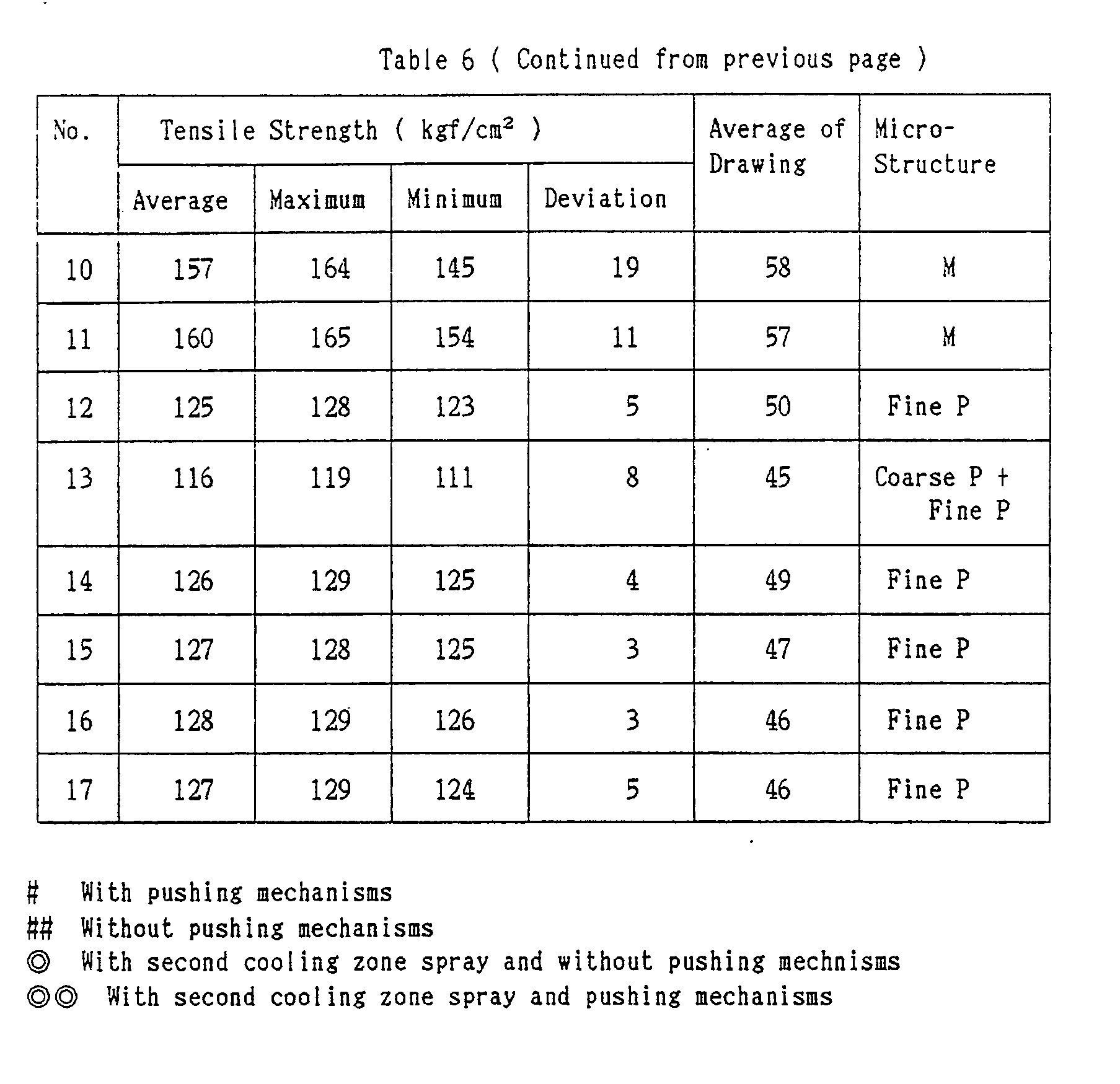
Claims (32)
transporting a hot-rolled and coiled wire rod (1) on a conveyer (3) in a state that said wire rod is in a form of continuous series of loops, characterized by comprizing the step of :
blasting air-water mist (18) to said wire rod and blasting air (5) to the back side of said wire rod from below to cool said wire rod at a cooling rate of 10 to 100 °C/sec.during the transportation, said air-water mist having an air to water ratio of 200 Nm³/m³ or less which is prepared from water of 0.5 to 10 m³/min.
trasnsporting a hot-rolled and coiled wire rod (1) on a conveyer (3) in a state that said wire rod is in a form of continuous series of loops, characterized by copmrising the step of :
blasting spray-water to said wire rod and blasting air (5) to the back side of said wire rod from below to cool said wire rod at a cooling rate of 10 to 100 °C/sec. during the transportation, said spray-water being fine particles which water is turned into from water of 0.5 to 10 m³ / min. by means of spraying.
transporting a hot-rolled and coiled wire rod (1) on a conveyer (3) in a state that said wire rod is in a form of continuous series of loops, having said wire rod advanced in zigzag during the transportation ; and
blasting air-water mist (18) to said wire rod and blasting air (5) to the back side of said wire rod from below to cool said wire rod at a cooling rate of 10 to 100 °C/sec. during the transportation, said air-water mist having an air to water ratio of 200 Nm³/m³ or less which is prepared from water of 0.5 to 10 m³/min.
transporting a hot-rolled and coiled wire rod (1) on a conveyer (3) in a state that said wire rod is in a form of continuous series of loops, having said wire rod advanced in zigzag during the transportation ; and
blasting spray-water to said wire rod and blasting air (5) to the back side of said wire rod from below to cool said wire rod at a cooling rate of 10 to 100 °C/sec. during the transportation, said spray-water mist being fine particles which are prepared from water of 0.5 to 10 m³/min. by means of spraying.
Applications Claiming Priority (4)
| Application Number | Priority Date | Filing Date | Title |
|---|---|---|---|
| JP22986488 | 1988-09-16 | ||
| JP229864/88 | 1988-09-16 | ||
| JP46625/89 | 1989-03-01 | ||
| JP4662589 | 1989-03-01 |
Publications (3)
| Publication Number | Publication Date |
|---|---|
| EP0359279A2 true EP0359279A2 (en) | 1990-03-21 |
| EP0359279A3 EP0359279A3 (en) | 1991-06-12 |
| EP0359279B1 EP0359279B1 (en) | 1994-07-06 |
Family
ID=26386733
Family Applications (1)
| Application Number | Title | Priority Date | Filing Date |
|---|---|---|---|
| EP89117113A Expired - Lifetime EP0359279B1 (en) | 1988-09-16 | 1989-09-15 | Method for rapid direct cooling of a hot-rolled wire rod |
Country Status (6)
| Country | Link |
|---|---|
| US (1) | US5146759A (en) |
| EP (1) | EP0359279B1 (en) |
| JP (1) | JP2721861B2 (en) |
| KR (1) | KR930003635B1 (en) |
| BR (1) | BR8904682A (en) |
| DE (1) | DE68916603T2 (en) |
Cited By (5)
| Publication number | Priority date | Publication date | Assignee | Title |
|---|---|---|---|---|
| WO1998045487A1 (en) * | 1997-04-08 | 1998-10-15 | Morgan Construction Company | Apparatus and method for cooling hot rolled steel rod |
| WO2003104501A3 (en) * | 2002-06-06 | 2004-01-29 | Four Industriel Belge | Method and device for patenting steel wires |
| EP1582600A1 (en) * | 2004-03-29 | 2005-10-05 | Fata Aluminium S.p.A. | Method and apparatus for cooling foundry castings |
| CN102974628A (en) * | 2012-12-05 | 2013-03-20 | 江苏永钢集团有限公司 | Aerial fog cooling device for wire air-cooling line |
| WO2020099688A1 (en) * | 2018-11-14 | 2020-05-22 | Druids Process Technology, S.L. | Cooling method and device for cooling a wire and corresponding wire-processing installation |
Families Citing this family (16)
| Publication number | Priority date | Publication date | Assignee | Title |
|---|---|---|---|---|
| US5992159A (en) * | 1995-05-25 | 1999-11-30 | Edwards; Christopher Francis | Method and apparatus for heat extraction by controlled spray cooling |
| US5592823A (en) * | 1996-03-12 | 1997-01-14 | Danieli United | Variable soft cooling header |
| KR100470673B1 (en) * | 2000-11-02 | 2005-03-07 | 주식회사 포스코 | Method for cooling of hot coil and equipment therefor |
| KR20020051081A (en) * | 2000-12-22 | 2002-06-28 | 이구택 | System for cooling hot rolled wire and method thereof |
| SE521767C2 (en) * | 2001-03-23 | 2003-12-02 | Foersvarets Materielverk | Method and apparatus for generating a liquid mist |
| DE10215229A1 (en) * | 2002-04-06 | 2003-10-16 | Sms Demag Ag | Device for cooling rolling stock within the cooling section of a rolling mill |
| CN100435990C (en) * | 2004-11-17 | 2008-11-26 | 首钢总公司 | After-roll reinforced cooling process for 82B wire rod steel strand |
| EP2166115A3 (en) | 2005-08-12 | 2010-11-10 | Kabushiki Kaisha Kobe Seiko Sho | Method for production of steel material having excellent scale detachment and steel wire material having excellent scale detachment |
| US20080011394A1 (en) * | 2006-07-14 | 2008-01-17 | Tyl Thomas W | Thermodynamic metal treating apparatus and method |
| CN102747213B (en) * | 2011-04-22 | 2014-04-30 | 宝山钢铁股份有限公司 | Cooling method for continuous heat treatment of high-strength steel |
| CN103406372B (en) * | 2013-08-20 | 2016-04-13 | 宣化钢铁集团有限责任公司 | A kind of high-speed rod wind mist Hybrid mode cooling means and device |
| CN104001741B (en) * | 2014-04-29 | 2016-03-30 | 张家港联峰钢铁研究所有限公司 | The 82B wire rod of a kind of small dimension height Cr rolls rear controlled cooling model method |
| CN104131151A (en) * | 2014-08-19 | 2014-11-05 | 江苏巨业电缆有限公司 | Copper wire cooling trough |
| CN104772346B (en) * | 2015-04-07 | 2017-01-04 | 首钢总公司 | A kind of method reducing soft state welding wire steel gren rod tensile strength |
| CN106975667B (en) * | 2015-12-22 | 2019-09-10 | Posco公司 | Wire coiling cooling device |
| CN111545698B (en) * | 2020-05-13 | 2021-11-19 | 上海长特锻造有限公司 | Forging process of fuel common rail |
Citations (10)
| Publication number | Priority date | Publication date | Assignee | Title |
|---|---|---|---|---|
| US3615083A (en) * | 1969-07-02 | 1971-10-26 | United States Steel Corp | Fluidized bed method and apparatus for continuously quenching coiled rod and wire |
| US3832788A (en) * | 1971-10-13 | 1974-09-03 | Sumitomo Metal Ind | Process and device for cooling hot-rolled wire rods |
| JPS51112721A (en) * | 1975-03-31 | 1976-10-05 | Sumitomo Metal Ind Ltd | Process for patenting steel wire |
| JPS53138917A (en) * | 1977-05-11 | 1978-12-04 | Nippon Steel Corp | Manufacture of high tensile high ductility wire rod |
| US4168993A (en) * | 1978-08-10 | 1979-09-25 | Morgan Construction Company | Process and apparatus for sequentially forming and treating steel rod |
| EP0069616A1 (en) * | 1981-06-22 | 1983-01-12 | Institut De Recherches De La Siderurgie Francaise (Irsid) | Device for cooling steel wire spirals in the rolling heat |
| EP0178799A2 (en) * | 1984-10-09 | 1986-04-23 | MORGAN CONSTRUCTION COMPANY (a Massachusetts corporation) | Apparatus for cooling hot rolled steel rod |
| EP0202057A2 (en) * | 1985-05-14 | 1986-11-20 | Allegheny Ludlum Steel Corporation | Low pressure misting jet |
| JPS62214133A (en) * | 1986-03-13 | 1987-09-19 | Kobe Steel Ltd | Continuous heat treatment of steel wire |
| DE3919178A1 (en) * | 1988-06-13 | 1989-12-14 | Toa Steel Co | METHOD FOR DIRECTLY PATENTING A HOT ROLLED ROLLING WIRE |
Family Cites Families (6)
| Publication number | Priority date | Publication date | Assignee | Title |
|---|---|---|---|---|
| DE1279605B (en) * | 1964-12-21 | 1968-10-10 | Roechlingsche Eisen & Stahl | Means and device for cooling wire rod coiled into rings |
| JPS5259015A (en) * | 1975-11-10 | 1977-05-16 | Shinko Wire Co Ltd | Patenting process of wire |
| DD132796A1 (en) * | 1977-10-21 | 1978-11-01 | Walter Worgt | DEVICE FOR COOLING ROLLING WIRE |
| JPS5698428A (en) * | 1980-01-09 | 1981-08-07 | Sumitomo Metal Ind Ltd | Preparation of high tensile wire material |
| US4407487A (en) * | 1980-01-15 | 1983-10-04 | Heurtey Metallurgie | Device for cooling metal articles |
| FR2597568B1 (en) * | 1986-04-18 | 1988-07-08 | Tecalemit Flexibles | NOVEL FLEXIBLE PIPE FOR USE AT HIGH PRESSURE AND MANUFACTURING METHOD THEREOF |
-
1989
- 1989-07-24 JP JP1188814A patent/JP2721861B2/en not_active Expired - Fee Related
- 1989-09-08 US US07/404,874 patent/US5146759A/en not_active Expired - Lifetime
- 1989-09-13 KR KR1019890013445A patent/KR930003635B1/en not_active IP Right Cessation
- 1989-09-15 DE DE68916603T patent/DE68916603T2/en not_active Expired - Fee Related
- 1989-09-15 EP EP89117113A patent/EP0359279B1/en not_active Expired - Lifetime
- 1989-09-18 BR BR898904682A patent/BR8904682A/en not_active IP Right Cessation
Patent Citations (10)
| Publication number | Priority date | Publication date | Assignee | Title |
|---|---|---|---|---|
| US3615083A (en) * | 1969-07-02 | 1971-10-26 | United States Steel Corp | Fluidized bed method and apparatus for continuously quenching coiled rod and wire |
| US3832788A (en) * | 1971-10-13 | 1974-09-03 | Sumitomo Metal Ind | Process and device for cooling hot-rolled wire rods |
| JPS51112721A (en) * | 1975-03-31 | 1976-10-05 | Sumitomo Metal Ind Ltd | Process for patenting steel wire |
| JPS53138917A (en) * | 1977-05-11 | 1978-12-04 | Nippon Steel Corp | Manufacture of high tensile high ductility wire rod |
| US4168993A (en) * | 1978-08-10 | 1979-09-25 | Morgan Construction Company | Process and apparatus for sequentially forming and treating steel rod |
| EP0069616A1 (en) * | 1981-06-22 | 1983-01-12 | Institut De Recherches De La Siderurgie Francaise (Irsid) | Device for cooling steel wire spirals in the rolling heat |
| EP0178799A2 (en) * | 1984-10-09 | 1986-04-23 | MORGAN CONSTRUCTION COMPANY (a Massachusetts corporation) | Apparatus for cooling hot rolled steel rod |
| EP0202057A2 (en) * | 1985-05-14 | 1986-11-20 | Allegheny Ludlum Steel Corporation | Low pressure misting jet |
| JPS62214133A (en) * | 1986-03-13 | 1987-09-19 | Kobe Steel Ltd | Continuous heat treatment of steel wire |
| DE3919178A1 (en) * | 1988-06-13 | 1989-12-14 | Toa Steel Co | METHOD FOR DIRECTLY PATENTING A HOT ROLLED ROLLING WIRE |
Non-Patent Citations (4)
| Title |
|---|
| PATENT ABSTRACTS OF JAPAN vol. 1, no. 4 (C-76), 10 March 1977; & JP - A - 51112721 (SUMITOMO) 10.05.1976 * |
| PATENT ABSTRACTS OF JAPAN vol. 12, no. 75 (C-480)(2922), 9 March 1988; & JP - A - 62214133 (KOBE STEEL) 19.09.1987 * |
| PATENT ABSTRACTS OF JAPAN vol. 3, no. 14, (C-36), 8 February 1979; & JP - A - 53138917 (SHIN NIPPON SEITETSU) 12.04.1978 * |
| PATENT ABSTRACTS OF JAPAN vol. 8, no. 118 (C-226)(1555), 31 May 1984; & JP - A - 5931831 (SHIN NIPPON SEITETSU) 21.02.1984 * |
Cited By (9)
| Publication number | Priority date | Publication date | Assignee | Title |
|---|---|---|---|---|
| WO1998045487A1 (en) * | 1997-04-08 | 1998-10-15 | Morgan Construction Company | Apparatus and method for cooling hot rolled steel rod |
| US5871596A (en) * | 1997-04-08 | 1999-02-16 | Morgan Construction Company | Apparatus and method for cooling hot rolled steel rod |
| WO2003104501A3 (en) * | 2002-06-06 | 2004-01-29 | Four Industriel Belge | Method and device for patenting steel wires |
| BE1014868A3 (en) * | 2002-06-06 | 2004-05-04 | Four Industriel Belge | METHOD AND DEVICE patenting STEEL SON |
| CN100370038C (en) * | 2002-06-06 | 2008-02-20 | 比利时工业炉公司 | Method and device for patenting steel wires |
| US7354493B2 (en) | 2002-06-06 | 2008-04-08 | Le Four Industriel Belge | Method and device for patenting steel wires |
| EP1582600A1 (en) * | 2004-03-29 | 2005-10-05 | Fata Aluminium S.p.A. | Method and apparatus for cooling foundry castings |
| CN102974628A (en) * | 2012-12-05 | 2013-03-20 | 江苏永钢集团有限公司 | Aerial fog cooling device for wire air-cooling line |
| WO2020099688A1 (en) * | 2018-11-14 | 2020-05-22 | Druids Process Technology, S.L. | Cooling method and device for cooling a wire and corresponding wire-processing installation |
Also Published As
| Publication number | Publication date |
|---|---|
| DE68916603D1 (en) | 1994-08-11 |
| JP2721861B2 (en) | 1998-03-04 |
| KR900004946A (en) | 1990-04-13 |
| JPH0310023A (en) | 1991-01-17 |
| US5146759A (en) | 1992-09-15 |
| BR8904682A (en) | 1990-05-01 |
| KR930003635B1 (en) | 1993-05-08 |
| EP0359279A3 (en) | 1991-06-12 |
| DE68916603T2 (en) | 1994-12-15 |
| EP0359279B1 (en) | 1994-07-06 |
Similar Documents
| Publication | Publication Date | Title |
|---|---|---|
| EP0359279B1 (en) | Method for rapid direct cooling of a hot-rolled wire rod | |
| CA1193176A (en) | Method for the production of improved railway rails by accelerated colling in line with the production rolling mill | |
| CA1259552A (en) | Method of and apparatus for heat-treating rails | |
| EP2674504A1 (en) | Method and system for thermal treatments of rails | |
| US5125987A (en) | Method for direct patenting of a hot-rolled wire rod | |
| US4242153A (en) | Methods for hot rolling and treating rod | |
| EP0536986A1 (en) | A method for steel surface hardening treatment and an apparatus therefor | |
| CA1265421A (en) | Method and apparatus for cooling rolled steels | |
| DE2165020A1 (en) | Method and device for the continuous annealing of strand-like material | |
| JPS5818403B2 (en) | Steel spring plate manufacturing method and device | |
| US4090697A (en) | Apparatus and method for treating wire | |
| US4871146A (en) | Apparatus for heat treatment of steel rods | |
| US7374624B1 (en) | Vertical plate dip quench | |
| CN112170799A (en) | Slab caster fan-shaped section cooling device and control method | |
| EP0181101B1 (en) | Apparatus and method for air cooling hot rolled steel rod | |
| JPH1017943A (en) | Method for directly quenching hot-rolled steel wire rod | |
| EP0582180B1 (en) | Heat treatment process for wire rods | |
| US4026731A (en) | Method for heat treating wire | |
| JP2541213B2 (en) | Shaped steel manufacturing equipment | |
| JPH09157750A (en) | High speed quenching method for steel pipe | |
| EP0086408A2 (en) | Method and apparatus for heat treating steel | |
| JP3552563B2 (en) | H-section steel flange cooling device and flange cooling method | |
| KR890002614B1 (en) | Process for manufacturing of high tension wire rod for pc steel wire | |
| JPS6035971B2 (en) | Link chain heat treatment equipment | |
| JPS6314047B2 (en) |
Legal Events
| Date | Code | Title | Description |
|---|---|---|---|
| PUAI | Public reference made under article 153(3) epc to a published international application that has entered the european phase |
Free format text: ORIGINAL CODE: 0009012 |
|
| 17P | Request for examination filed |
Effective date: 19890915 |
|
| AK | Designated contracting states |
Kind code of ref document: A2 Designated state(s): DE FR GB |
|
| PUAL | Search report despatched |
Free format text: ORIGINAL CODE: 0009013 |
|
| AK | Designated contracting states |
Kind code of ref document: A3 Designated state(s): DE FR GB |
|
| 17Q | First examination report despatched |
Effective date: 19921102 |
|
| GRAA | (expected) grant |
Free format text: ORIGINAL CODE: 0009210 |
|
| AK | Designated contracting states |
Kind code of ref document: B1 Designated state(s): DE FR GB |
|
| REF | Corresponds to: |
Ref document number: 68916603 Country of ref document: DE Date of ref document: 19940811 |
|
| ET | Fr: translation filed | ||
| PLBE | No opposition filed within time limit |
Free format text: ORIGINAL CODE: 0009261 |
|
| STAA | Information on the status of an ep patent application or granted ep patent |
Free format text: STATUS: NO OPPOSITION FILED WITHIN TIME LIMIT |
|
| 26N | No opposition filed | ||
| REG | Reference to a national code |
Ref country code: FR Ref legal event code: TP |
|
| REG | Reference to a national code |
Ref country code: GB Ref legal event code: 732E |
|
| REG | Reference to a national code |
Ref country code: GB Ref legal event code: IF02 |
|
| PGFP | Annual fee paid to national office [announced via postgrant information from national office to epo] |
Ref country code: GB Payment date: 20040910 Year of fee payment: 16 |
|
| PGFP | Annual fee paid to national office [announced via postgrant information from national office to epo] |
Ref country code: FR Payment date: 20040915 Year of fee payment: 16 |
|
| PGFP | Annual fee paid to national office [announced via postgrant information from national office to epo] |
Ref country code: DE Payment date: 20040927 Year of fee payment: 16 |
|
| PG25 | Lapsed in a contracting state [announced via postgrant information from national office to epo] |
Ref country code: GB Free format text: LAPSE BECAUSE OF NON-PAYMENT OF DUE FEES Effective date: 20050915 |
|
| PG25 | Lapsed in a contracting state [announced via postgrant information from national office to epo] |
Ref country code: DE Free format text: LAPSE BECAUSE OF NON-PAYMENT OF DUE FEES Effective date: 20060401 |
|
| GBPC | Gb: european patent ceased through non-payment of renewal fee |
Effective date: 20050915 |
|
| PG25 | Lapsed in a contracting state [announced via postgrant information from national office to epo] |
Ref country code: FR Free format text: LAPSE BECAUSE OF NON-PAYMENT OF DUE FEES Effective date: 20060531 |
|
| REG | Reference to a national code |
Ref country code: FR Ref legal event code: ST Effective date: 20060531 |