EP0178799A2 - Apparatus for cooling hot rolled steel rod - Google Patents
Apparatus for cooling hot rolled steel rod Download PDFInfo
- Publication number
- EP0178799A2 EP0178799A2 EP85306668A EP85306668A EP0178799A2 EP 0178799 A2 EP0178799 A2 EP 0178799A2 EP 85306668 A EP85306668 A EP 85306668A EP 85306668 A EP85306668 A EP 85306668A EP 0178799 A2 EP0178799 A2 EP 0178799A2
- Authority
- EP
- European Patent Office
- Prior art keywords
- nozzles
- water
- rings
- cooling
- conveyor
- Prior art date
- Legal status (The legal status is an assumption and is not a legal conclusion. Google has not performed a legal analysis and makes no representation as to the accuracy of the status listed.)
- Withdrawn
Links
Images


Classifications
-
- C—CHEMISTRY; METALLURGY
- C21—METALLURGY OF IRON
- C21D—MODIFYING THE PHYSICAL STRUCTURE OF FERROUS METALS; GENERAL DEVICES FOR HEAT TREATMENT OF FERROUS OR NON-FERROUS METALS OR ALLOYS; MAKING METAL MALLEABLE, e.g. BY DECARBURISATION OR TEMPERING
- C21D9/00—Heat treatment, e.g. annealing, hardening, quenching or tempering, adapted for particular articles; Furnaces therefor
- C21D9/52—Heat treatment, e.g. annealing, hardening, quenching or tempering, adapted for particular articles; Furnaces therefor for wires; for strips ; for rods of unlimited length
- C21D9/54—Furnaces for treating strips or wire
- C21D9/56—Continuous furnaces for strip or wire
- C21D9/573—Continuous furnaces for strip or wire with cooling
- C21D9/5732—Continuous furnaces for strip or wire with cooling of wires; of rods
-
- B—PERFORMING OPERATIONS; TRANSPORTING
- B21—MECHANICAL METAL-WORKING WITHOUT ESSENTIALLY REMOVING MATERIAL; PUNCHING METAL
- B21C—MANUFACTURE OF METAL SHEETS, WIRE, RODS, TUBES OR PROFILES, OTHERWISE THAN BY ROLLING; AUXILIARY OPERATIONS USED IN CONNECTION WITH METAL-WORKING WITHOUT ESSENTIALLY REMOVING MATERIAL
- B21C47/00—Winding-up, coiling or winding-off metal wire, metal band or other flexible metal material characterised by features relevant to metal processing only
- B21C47/26—Special arrangements with regard to simultaneous or subsequent treatment of the material
- B21C47/262—Treatment of a wire, while in the form of overlapping non-concentric rings
Definitions
- This invention relates generally to the controlled cooling of hot rolled steel products such as rods and the like in direct sequence with the rolling operation in order to achieve predetermined metallurgical qualities.
- the rod sizes that are processed in installations of the foregoing type typically range from 5-19 mm. in diameter.
- air cooling has proven to be fast enough to achieve acceptable tensile strengths.
- air cooling rates are not sufficiently rapid, thus yielding tensile strengths which are below acceptable levels for certain applications.
- a primary objective of the present invention is the provision of an improved cooling conveyor having successive zones adapted to continuously air cool the smaller rod sizes in a conventional manner, with at least some of the same zones being adapted to cool with water sprays or with water laden air when accelerated cooling of the larger rod sizes is required.
- All conveyor zones have forced air cooling systems which include air nozzles underlying the path of ring travel over the conveyor rollers, and with air ducts connecting the air nozzles to motor driven fans.
- the accelerated cooling zones are additionally provided with water cooling systems, including water nozzles fed by appropriate piping.
- the nozzles are arranged directly adjacent to the path of ring travel so as to spray water directly onto the rings, preferably from both above and below.
- the water nozzles are arranged in the air ducts to spray water droplets into the forced air streams being generated by the motor driven fans, thereby producing water laden air which passes upwardly through the air nozzles for application to the rod rings.
- the air ducts and nozzles serve the dual function of applying air to the rod rings, and/or draining away excess water, depending upon which mode of operation is selected.
- This total versatility makes it possible for the accelerated cooling zones of the conveyor to operate on the entire range of rod sizes, even when only air cooling is being employed.
- Hot rolled steel rod emerges from the finishing block and is conveyed by means of water cooled delivery pipes 12 to a laying head 14.
- the laying head forms the rod into a continuous series of rings 16 which are received on a short conveyor belt 18.
- the belt 18 is driven at an appropriate speed which arranges the rings in an overlapping offset pattern as they move onto the cooling conveyor 20.
- Conveyor 20 has mutually spaced driven conveyor rollers 22 which propel the offset overlapping rings 16 in the direction indicated schematically by the arrow 24 in Figure 2.
- the conveyor 20 is subdivided into a plurality of sections denoted by the letters A & B .
- the B sections are adapted to cool the rings in a conventional manner with forced air only, and thus may comprise any one of a number of known designs, an example of which is described in U.S. Patent No.4,448,401 (Jalil et al).
- the A sections have the multiple capability of applying air alone, or either water sprays or water laden air.
- a conveyor section A wherein the driven conveyor rollers 22 overlie a conveyor deck made up of refractory filled channel members 26.
- the channel members 26 are spaced one from the other to provide "first" air nozzles 28 arranged beneath the path of travel of the rod rings 16 over the conveyor rollers.
- the air nozzles 28 underlie the rollers 22 and extend across the entire conveyor width.
- the air nozzles 28 communicate with any one of a number of underlying air ducts 30, each being supplied with forced air by a motor driven fan 32.
- the ducts are suitably insulated with refractory, each have a sloping bottom wall 34.
- Each duct is interiorly subdivided by partitions 36 (see Figure 5) into a center chamber 38 and two side chambers 40.
- the output of the fan 32 may be selectively divided by baffles (not shown) so as to direct a greater proportion of cooling air into the side chambers 40 for application through the nozzles 28 at the sides of the conveyor where the density of ring overlap is greatest.
- adjustable deflectors 42 are provided along the upper edges of the partitions 36 to further control the application of cooling air through the nozzles 28.
- the air nozzles 28, ducts 30 and air driven fans 32 are features common to both conveyor sections A and B.
- Water supply pipes 43 extend through at least some of the refractory filled channel members 26 underlying certain of the spaces between the conveyor rollers 22.
- the water supply pipes 43 have upwardly directed "second" nozzles 44.
- additional water supply pipes 45 are arranged over the conveyor rollers on cover sections 48.
- the supply pipes 45 carry additional downwardly directed second water nozzles 46.
- the water supply pipes 43, 45 are connected via flexible piping 50 to distribution headers 52 which in turn are connected via a shut off valve 54 to a main water header 56.
- the arrangement of the nozzles 44, 46 is preferably such that in comparison to the amount of water applied at the conveyor center, a greater amount of water is applied at the conveyor edges.
- each air duct 30 has a drain opening 58 leading to a small sump 60.
- the sumps are in turn connected by means of drain piping 62 to the collectors 64 shown in Figure 1.
- Flap valves 66 are associated with each of the drain openings 58.
- the valves may be adjusted manually by any convenient means (not shown) between open positions as shown in the drawings, and closed positions blocking the drain openings.
- the conveyor cover sections 48 have top openings 68 communicating with a steam vent 70 and a steam extraction duct 72. After first disconnecting the flexible piping 50, the cover sections may be pivoted to open positions indicated by broken lines at 70'.
- the conveyor sections A and B can be operated to cool the rod rings with air only, with water sprays only, or with mist-like water laden air.
- the flap valves 66 and the water shut off valve 54 will be closed, the flexible piping 50 will be disconnected and the cover sections 48 raised to their open positions 70'. Thereafter, by operating the fans 32, air will be driven upwardly through the ducts 30 and first air nozzles 28 for application to the rod rings moving over the driven rollers 22.
- the fans 32 are shut down and slide plates 74 (see Figure 3) are manually inserted across the ducts 30 to safeguard the fans against exposure to moisture.
- the cover sections 48 are lowered into place and the flexible piping 50 is connected. Thereafter, with the flap valves 66 open, the main shut off valve 54 is opened to feed water to the second water nozzles 44, 46.
- the water is applied from above and below the rings as a fine spray. Much of the water is converted to steam by the heat of the rod, and this steam is exhausted from the conveyor through the vents 70 and extraction ducts 72. The remainder of the water runs down through the first air nozzles 28 into the ducts 30.
- Gravity directs the water down the sloping duct bottoms 34 and through the drain openings 58 into the sumps 60, and from there through the drain piping 62 to the collectors 64.
- water from the collectors 64 may be filtered and recirculated back to the main water header 56.
- the temperature of the water being applied through nozzles 44 and 46 may be controlled, as by preheating, in order to achieve selected cooling rates for the rod rings being processed on the conveyor.
- FIG. 6-8 An alternate embodiment of a conveyor section A is shown in Figures 6-8. Those elements which are common to both embodiments have been designated by the same reference numerals.
- the "second" water nozzles 76 are located exclusively in the air duct 30.
- the cover sections 78 are removable by means of lifting eyes 80, and are detachably connected by means of lateral branch conduits 82 to steam exhaust ducts 84.
- the water nozzles 76 are arranged to direct a fine water spray into the air stream being generated by the fans 32.
- the resulting water laden air passes upwardly through the first nozzles 28 for application to the rod rings being carried along the conveyor by the driven rollers 22.
- FIG 9 shows a further modification of the embodiment illustrated in Figures 6-8.
- the "second" nozzles are again located exclusively in the air duct 30.
- the nozzles 86 are arrayed in multiple rows r l , r 2 .
- the rows r l are located in the center chamber 38 whereas the rows r 2 are located respectively in the side chambers 40.
- the nozzles 86 are fed by mixers 88 with water by one branch 90 connected to a water main 92, and with compressed air by another branch 94 connected to an air manifold 96.
- the nozzles 86 produce a fine mist which mixes more thoroughly with the air output of the fans 32.
- FIG. 10 Still another embodiment of the invention is shown in Figure 10 where the conveyor deck is comprised of a series of rectangular tubes 98 spaced as at 100 to define first air nozzles. Selected ones of the tubes are provided with a series of second water nozzles 102. Cooling water is circulated through the tubes 98, and the nozzles 102 spray that cooling water upwardly onto the rings being transported over the conveyor rollers 22.
- the first nozzles 100 allow excess water to drain back to the underlying air plenum (not shown).
- conveyor sections A and B may be operated with cooling air only, in accordance with conventional practice, in a controlled manner according to the principles of the well-known Stelmor process as described, e.g. in U.S. Patent Nos. 3,231,432; 3,320,101 and 3, 390,871.
- the conveyor cover sections are opened or removed to accommodate unrestricted upward flow of the cooling air through and around the overlapped rod rings moving along the conveyor. Since all of the conveyor sections are equipped with air cooling nozzles, ducts and fans, the application of forced air is substantially continuous along the entire conveyor length.
- each of the water cooling modes is characterised at least in part by an upward application of water sprays or water laden air. Because the overlapped rod rings are moving over the spaced conveyor rollers, this upward application is necessarily intermittent. This is believed to be beneficial in that it allows water applied to the hot rod surfaces to vaporize into steam and to move away from the rod surfaces before the next successive water application. Because the steam is not trapped against the rod surfaces, as would be the case with total immersion in a water bath, an insulating steam blanket is not formed, and thus more rapid cooling rates may be achieved.
- conveyor sections A and B can be varied to suit operating conditions. For example, it may be desirable to have several consecutive A sections at the beginning of the conveyor, or for that matter, to have all conveyor sections of the A type.
Landscapes
- Engineering & Computer Science (AREA)
- Chemical & Material Sciences (AREA)
- Mechanical Engineering (AREA)
- Physics & Mathematics (AREA)
- Thermal Sciences (AREA)
- Crystallography & Structural Chemistry (AREA)
- Materials Engineering (AREA)
- Metallurgy (AREA)
- Organic Chemistry (AREA)
- Heat Treatment Of Strip Materials And Filament Materials (AREA)
- Heat Treatments In General, Especially Conveying And Cooling (AREA)
Abstract
Description
- This invention relates generally to the controlled cooling of hot rolled steel products such as rods and the like in direct sequence with the rolling operation in order to achieve predetermined metallurgical qualities.
- The controlled cooling of hot rolled steel rod in direct sequence with the rolling thereof began approximately twenty years ago with the process described in U.S. Patent No.3,231,432 (McLean et al). This process involves hot-rolling the rod and thereafter directly coiling it onto an open conveyor in spread out ring form while the microstructure of the steel is still in a condition of highly uniform, relatively small austenite grain size. While moving along the conveyor, the rings are air cooled through allotropic transformation. This produces a "patented" microstructure, i.e., a microstructure sufficiently equivalent to that achieved by air or lead patenting so as to enable the rod to be subsequently processed to a finished product, as for example by being drawn into wire, without additional heat treatment.
- In the earlier installations of this process, chain-type conveyors were employed. However, because of the tendency of the rings to undergo scratching as a result of their being dragged over stationary support rails loocated between the chains, and because of the non-uniform cooling which results from prolonged area contact with such rails, the use of chain-type conveyors has of late been largely discontinued in favour of roller conveyors of the type shown for example in U.S. Patent No.3,390,900 (Wilson). Here, the rings are transported over driven rollers, with air nozzles arranged between the rollers to blow cooling air upwardly through the rings.
- Further improvements in uniformity of cooling and flexibility of operation have been achieved by arranging the air cooling nozzles directly under the conveyor rollers, as shown for example in U.S. Patent No.4,448,401 (Jalil et al).
- The rod sizes that are processed in installations of the foregoing type typically range from 5-19 mm. in diameter. For rods below about 9 mm. in diameter, air cooling has proven to be fast enough to achieve acceptable tensile strengths. However, for rods 9 mm. and above in diameter, air cooling rates are not sufficiently rapid, thus yielding tensile strengths which are below acceptable levels for certain applications.
- Attempts have been made at achieving increased cooling rates by employing water as a cooling medium. See for example U.S. Patent No.4,395,022 (Paulus et al) which describes an apparatus for cooling hot rolled steel products, including rod, by immersion in a water bath. Cooling by water immersion has reportedly achieved somewhat accelerated cooling rates with improved tensiles for larger rod sizes. However, uniform results have been difficult to achieve, primarily because of the difficulty of maintaining optimum water chemistry. This problem is compounded by the need to continuously remove contaminants such as dirt, mill scale, etc. from the water bath.
- As shown by U.S. Patent No.4,168,993 (Wilson et al), some work has been done with water sprays. The problem with these arrangements, however, is that certain conveyor zones are limited to cooling by a water spray application, whereas other conveyor zones are limited to cooling by air. If only air cooling is required, as for example when processing smaller diameter rods, then the water cooling zones must be shut down. Thus, as the rod moves along the conveyor, it experiences extended intervals (while moving through the inoperative water cooling zone) when no coolant is being applied. This seriously compromises the overall effectiveness of such processes.
- Because of the foregoing problems, when rolling rod diameters of 9 mm. and above, most mills either draw wire to greater reductions, or use alloying elements to increase the hardenability of the steel, or resort to offline lead or salt patenting heat treatments. The first of these alternatives yields mixed results, and the second and third alternatives significantly increase tonnage costs. In short, the prior art has failed to satisfactorily meet the demands of the industry when processing the larger rod sizes ranging from 9 - 19 mm. in diameter.
- A primary objective of the present invention is the provision of an improved cooling conveyor having successive zones adapted to continuously air cool the smaller rod sizes in a conventional manner, with at least some of the same zones being adapted to cool with water sprays or with water laden air when accelerated cooling of the larger rod sizes is required.
- All conveyor zones have forced air cooling systems which include air nozzles underlying the path of ring travel over the conveyor rollers, and with air ducts connecting the air nozzles to motor driven fans. The accelerated cooling zones are additionally provided with water cooling systems, including water nozzles fed by appropriate piping. In one embodiment, the nozzles are arranged directly adjacent to the path of ring travel so as to spray water directly onto the rings, preferably from both above and below. In another embodiment, the water nozzles are arranged in the air ducts to spray water droplets into the forced air streams being generated by the motor driven fans, thereby producing water laden air which passes upwardly through the air nozzles for application to the rod rings.
- When either of the above-described water cooling embodiments is in operation, a portion of the water being applied to the hot rod will be converted to steam. The steam is captured by removable hoods overlying the conveyor and removed therefrom by appropriate vents and ducting. The remainder of the water drains back downwardly through the air nozzles into the air ducts, where it is collected and removed for subsequent filtering and recirculation.
- Thus it will be seen that the air ducts and nozzles serve the dual function of applying air to the rod rings, and/or draining away excess water, depending upon which mode of operation is selected. This total versatility makes it possible for the accelerated cooling zones of the conveyor to operate on the entire range of rod sizes, even when only air cooling is being employed.
-
- Figure 1 is a somewhat schematic illustration, in side elevation, of a cooling installation in accordance with the present invention,
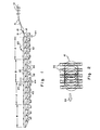
- Figure 2 is a partial plan view illustrating the offset overlapping relationship of the rings moving along the conveyor;
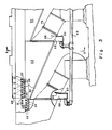
- Figure 3 is an enlarged side elevational view, with portions broken away, showing one embodiment of a conveyor section in accordance with the present invention, having both air and water cooling capabilities;
- Figure 4 is a further enlarged and partially broken away side elevational view of a portion of the conveyor shown in Figure 3;
- Figure 5 is a cross-sectional view of the conveyor taken along line 5-5 of Figure 3;
- Figure 6 is a side elevational view, with portions broken away, showing another embodiment of a conveyor section in accordance with the present invention having both air and water cooling capabilities;
- Figure 7 is a cross-sectional view of the conveyor taken along line 7-7 of Figure 6;
- Figure 8 is a horizontal sectional view taken along line 8-8 of Figure 7 and showing one type of water nozzle arrangement; and
- Figure 9 is a view similar to Figure 8 showing another water nozzle arrangement.
- Referring initially to Figures 1 and 2, the last roll pairs of a conventional finishing block are diagrammatically shown at 10. Hot rolled steel rod emerges from the finishing block and is conveyed by means of water cooled
delivery pipes 12 to a layinghead 14. The laying head forms the rod into a continuous series ofrings 16 which are received on ashort conveyor belt 18. Thebelt 18 is driven at an appropriate speed which arranges the rings in an overlapping offset pattern as they move onto thecooling conveyor 20.Conveyor 20 has mutually spaced drivenconveyor rollers 22 which propel theoffset overlapping rings 16 in the direction indicated schematically by thearrow 24 in Figure 2. - In the embodiment herein illustrated, the
conveyor 20 is subdivided into a plurality of sections denoted by the letters A & B. The B sections are adapted to cool the rings in a conventional manner with forced air only, and thus may comprise any one of a number of known designs, an example of which is described in U.S. Patent No.4,448,401 (Jalil et al). However, the A sections have the multiple capability of applying air alone, or either water sprays or water laden air. - Referring additionally to Figures 3-5, one embodiment of a conveyor section A is shown wherein the driven
conveyor rollers 22 overlie a conveyor deck made up of refractory filledchannel members 26. Thechannel members 26 are spaced one from the other to provide "first"air nozzles 28 arranged beneath the path of travel of therod rings 16 over the conveyor rollers. Preferably, theair nozzles 28 underlie therollers 22 and extend across the entire conveyor width. - The
air nozzles 28 communicate with any one of a number of underlyingair ducts 30, each being supplied with forced air by a motor drivenfan 32. The ducts are suitably insulated with refractory, each have a slopingbottom wall 34. Each duct is interiorly subdivided by partitions 36 (see Figure 5) into acenter chamber 38 and twoside chambers 40. The output of thefan 32 may be selectively divided by baffles (not shown) so as to direct a greater proportion of cooling air into theside chambers 40 for application through thenozzles 28 at the sides of the conveyor where the density of ring overlap is greatest. Additionally,adjustable deflectors 42 are provided along the upper edges of thepartitions 36 to further control the application of cooling air through thenozzles 28. The air nozzles 28,ducts 30 and air drivenfans 32 are features common to both conveyor sections A and B. -
Water supply pipes 43 extend through at least some of the refractory filledchannel members 26 underlying certain of the spaces between theconveyor rollers 22. Thewater supply pipes 43 have upwardly directed "second"nozzles 44. Preferably, additionalwater supply pipes 45 are arranged over the conveyor rollers oncover sections 48. Thesupply pipes 45 carry additional downwardly directedsecond water nozzles 46. Thewater supply pipes flexible piping 50 todistribution headers 52 which in turn are connected via a shut offvalve 54 to amain water header 56. The arrangement of thenozzles - As can be best seen in Figure 3, the sloping
bottom wall 34 of eachair duct 30 has adrain opening 58 leading to asmall sump 60. The sumps are in turn connected by means of drain piping 62 to thecollectors 64 shown in Figure 1. -
Flap valves 66 are associated with each of thedrain openings 58. The valves may be adjusted manually by any convenient means (not shown) between open positions as shown in the drawings, and closed positions blocking the drain openings. - As shown in Figure 5, at least some of the
conveyor cover sections 48 havetop openings 68 communicating with asteam vent 70 and asteam extraction duct 72. After first disconnecting theflexible piping 50, the cover sections may be pivoted to open positions indicated by broken lines at 70'. - In operation, the conveyor sections A and B can be operated to cool the rod rings with air only, with water sprays only, or with mist-like water laden air. When cooling with air only, the
flap valves 66 and the water shut offvalve 54 will be closed, theflexible piping 50 will be disconnected and thecover sections 48 raised to their open positions 70'. Thereafter, by operating thefans 32, air will be driven upwardly through theducts 30 andfirst air nozzles 28 for application to the rod rings moving over the drivenrollers 22. - When cooling with water only, the
fans 32 are shut down and slide plates 74 (see Figure 3) are manually inserted across theducts 30 to safeguard the fans against exposure to moisture. Thecover sections 48 are lowered into place and theflexible piping 50 is connected. Thereafter, with theflap valves 66 open, the main shut offvalve 54 is opened to feed water to thesecond water nozzles vents 70 andextraction ducts 72. The remainder of the water runs down through thefirst air nozzles 28 into theducts 30. Gravity directs the water down the slopingduct bottoms 34 and through thedrain openings 58 into thesumps 60, and from there through the drain piping 62 to thecollectors 64. Although not illustrated in the drawings, it will be understood that water from thecollectors 64 may be filtered and recirculated back to themain water header 56. It should also be understood that the temperature of the water being applied throughnozzles - An alternate embodiment of a conveyor section A is shown in Figures 6-8. Those elements which are common to both embodiments have been designated by the same reference numerals. Here it will be seen that the "second"
water nozzles 76 are located exclusively in theair duct 30. Thecover sections 78 are removable by means of liftingeyes 80, and are detachably connected by means oflateral branch conduits 82 to steamexhaust ducts 84. The water nozzles 76 are arranged to direct a fine water spray into the air stream being generated by thefans 32. The resulting water laden air passes upwardly through thefirst nozzles 28 for application to the rod rings being carried along the conveyor by the drivenrollers 22. Steam is vented from thecover sections 78 through thebranch conduits 82 and communicatingexhaust ducts 84, and excess water again drains back through thenozzles 28 into theair ducts 30 for removal as previously described. When operating with air only, thewater nozzles 76 are shut down, thecover sections 78 are removed, and theflap valves 66 are closed. - Figure 9 shows a further modification of the embodiment illustrated in Figures 6-8. Here, the "second" nozzles are again located exclusively in the
air duct 30. Thenozzles 86 are arrayed in multiple rows rl, r2. The rows rl are located in thecenter chamber 38 whereas the rows r2 are located respectively in theside chambers 40. Thenozzles 86 are fed bymixers 88 with water by onebranch 90 connected to a water main 92, and with compressed air by anotherbranch 94 connected to anair manifold 96. Thenozzles 86 produce a fine mist which mixes more thoroughly with the air output of thefans 32. - Still another embodiment of the invention is shown in Figure 10 where the conveyor deck is comprised of a series of
rectangular tubes 98 spaced as at 100 to define first air nozzles. Selected ones of the tubes are provided with a series ofsecond water nozzles 102. Cooling water is circulated through thetubes 98, and thenozzles 102 spray that cooling water upwardly onto the rings being transported over theconveyor rollers 22. Here again, thefirst nozzles 100 allow excess water to drain back to the underlying air plenum (not shown). - Having thus described several embodiments of an apparatus in accordance with the present invention, the advantageuous features thereof will now be appreciated by those skilled in the art. When processing the smaller diameter rods (below 9 mm.), conveyor sections A and B may be operated with cooling air only, in accordance with conventional practice, in a controlled manner according to the principles of the well-known Stelmor process as described, e.g. in U.S. Patent Nos. 3,231,432; 3,320,101 and 3, 390,871.
- Under such circumstances, the conveyor cover sections are opened or removed to accommodate unrestricted upward flow of the cooling air through and around the overlapped rod rings moving along the conveyor. Since all of the conveyor sections are equipped with air cooling nozzles, ducts and fans, the application of forced air is substantially continuous along the entire conveyor length.
- When the large diameter rods are being processed, more rapid cooling rates can be achieved by shifting over the operation of the conveyor sections A from the air cooling mode to one of the previously described water cooling modes. Each of the water cooling modes is characterised at least in part by an upward application of water sprays or water laden air. Because the overlapped rod rings are moving over the spaced conveyor rollers, this upward application is necessarily intermittent. This is believed to be beneficial in that it allows water applied to the hot rod surfaces to vaporize into steam and to move away from the rod surfaces before the next successive water application. Because the steam is not trapped against the rod surfaces, as would be the case with total immersion in a water bath, an insulating steam blanket is not formed, and thus more rapid cooling rates may be achieved.
- It will be understood that the sequential arrangement of conveyor sections A and B can be varied to suit operating conditions. For example, it may be desirable to have several consecutive A sections at the beginning of the conveyor, or for that matter, to have all conveyor sections of the A type.
Claims (12)
Applications Claiming Priority (2)
| Application Number | Priority Date | Filing Date | Title |
|---|---|---|---|
| US65865884A | 1984-10-09 | 1984-10-09 | |
| US658658 | 1984-10-09 |
Publications (2)
| Publication Number | Publication Date |
|---|---|
| EP0178799A2 true EP0178799A2 (en) | 1986-04-23 |
| EP0178799A3 EP0178799A3 (en) | 1986-12-30 |
Family
ID=24642134
Family Applications (1)
| Application Number | Title | Priority Date | Filing Date |
|---|---|---|---|
| EP85306668A Withdrawn EP0178799A3 (en) | 1984-10-09 | 1985-09-19 | Apparatus for cooling hot rolled steel rod |
Country Status (5)
| Country | Link |
|---|---|
| EP (1) | EP0178799A3 (en) |
| JP (1) | JPS6192719A (en) |
| CN (1) | CN85107297A (en) |
| BR (1) | BR8504980A (en) |
| IN (1) | IN164702B (en) |
Cited By (9)
| Publication number | Priority date | Publication date | Assignee | Title |
|---|---|---|---|---|
| EP0359279A2 (en) * | 1988-09-16 | 1990-03-21 | Toa Steel Co., Ltd. | Method for rapid direct cooling of a hot-rolled wire rod |
| FR2650298A1 (en) * | 1988-06-13 | 1991-02-01 | Toa Steel Co Ltd | DIRECT PATENTING METHOD FOR HOT ROLLED METAL WIRE |
| FR2677904A1 (en) * | 1991-06-20 | 1992-12-24 | Siderurgie Fse Inst Rech | Cooling (ventilation) diffuser box intended to be coupled up to a conveyor cooling module at the output of a hot rolling mill for wire |
| EP0942069A1 (en) * | 1998-03-10 | 1999-09-15 | Sms Schloemann-Siemag Aktiengesellschaft | Cooling chamber for a roller conveyor |
| WO2003104501A3 (en) * | 2002-06-06 | 2004-01-29 | Four Industriel Belge | Method and device for patenting steel wires |
| CN101480669B (en) * | 2008-01-07 | 2011-04-13 | 宝山钢铁股份有限公司 | Stelmor line cooling method and cooling apparatus of high-speed rod-rolling mill |
| CN110042212A (en) * | 2019-04-25 | 2019-07-23 | 常州机电职业技术学院 | Cooling device for machine part |
| CN112538565A (en) * | 2020-11-18 | 2021-03-23 | 河钢股份有限公司承德分公司 | Method for shortening coiling time period |
| CN114891986A (en) * | 2022-05-20 | 2022-08-12 | 佛山市百燊工业科技有限公司 | Aging furnace |
Families Citing this family (11)
| Publication number | Priority date | Publication date | Assignee | Title |
|---|---|---|---|---|
| JP2764168B2 (en) * | 1988-06-13 | 1998-06-11 | トーア・スチール株式会社 | Steam-water mist cooling device for hot rolled wire |
| CN1064567C (en) * | 1998-02-23 | 2001-04-18 | 冶金工业部钢铁研究总院 | Cooling control method used for steels after hot rolled |
| CN102294371B (en) * | 2011-05-25 | 2013-11-13 | 中色科技股份有限公司 | Ventilating and cooling device and cooling method of hot-rolled coil yard machine |
| CN102626719A (en) * | 2012-04-24 | 2012-08-08 | 青岛钢铁控股集团有限责任公司 | Wire production controlled cooling device and wire production equipment |
| CN103008370B (en) * | 2012-12-11 | 2015-04-22 | 西安建筑科技大学 | Cooling control method for improving strength of hot rolled ribbed coiled reinforced bars |
| CN103406372B (en) * | 2013-08-20 | 2016-04-13 | 宣化钢铁集团有限责任公司 | A kind of high-speed rod wind mist Hybrid mode cooling means and device |
| CN103406373B (en) * | 2013-08-26 | 2015-04-22 | 武汉钢铁(集团)公司 | Suspension movable type controlled cooling production line for high-speed wire rods |
| CN103691747B (en) * | 2013-09-22 | 2016-02-10 | 宣化钢铁集团有限责任公司 | A kind of aerosol cooling spray controlled for steel cooling |
| CN104438384B (en) * | 2014-12-23 | 2016-05-25 | 江苏东方成套设备制造有限公司 | Valve snail is rolled rear cooling device |
| JP6368831B1 (en) * | 2017-06-19 | 2018-08-01 | 中外炉工業株式会社 | Metal strip cooling system |
| CN111020153B (en) * | 2019-12-03 | 2021-08-24 | 南通迪瓦特节能风机有限公司 | Bar air cooling system of steel mill bar production line |
Citations (7)
| Publication number | Priority date | Publication date | Assignee | Title |
|---|---|---|---|---|
| US3231432A (en) * | 1964-10-08 | 1966-01-25 | Morgan Construction Co | Process for the quenching of hot rolled rods in direct sequence with rod mill |
| US3390871A (en) * | 1962-08-24 | 1968-07-02 | Morgan Construction Co | Apparatus for the controlled cooling of rods |
| US3930900A (en) * | 1974-10-21 | 1976-01-06 | Morgan Construction Company | Process for cooling hot rolled steel rod |
| US4168993A (en) * | 1978-08-10 | 1979-09-25 | Morgan Construction Company | Process and apparatus for sequentially forming and treating steel rod |
| EP0069616A1 (en) * | 1981-06-22 | 1983-01-12 | Institut De Recherches De La Siderurgie Francaise (Irsid) | Device for cooling steel wire spirals in the rolling heat |
| JPS5931831A (en) * | 1982-08-17 | 1984-02-21 | Nippon Steel Corp | Cooler for wire rod |
| US4448401A (en) * | 1982-11-22 | 1984-05-15 | Morgan Construction Company | Apparatus for combined hot rolling and treating steel rod |
Family Cites Families (1)
| Publication number | Priority date | Publication date | Assignee | Title |
|---|---|---|---|---|
| JPS50112257A (en) * | 1974-02-14 | 1975-09-03 |
-
1985
- 1985-09-04 IN IN730/DEL/85A patent/IN164702B/en unknown
- 1985-09-19 EP EP85306668A patent/EP0178799A3/en not_active Withdrawn
- 1985-10-07 CN CN198585107297A patent/CN85107297A/en active Pending
- 1985-10-08 BR BR8504980A patent/BR8504980A/en unknown
- 1985-10-09 JP JP22384485A patent/JPS6192719A/en active Pending
Patent Citations (7)
| Publication number | Priority date | Publication date | Assignee | Title |
|---|---|---|---|---|
| US3390871A (en) * | 1962-08-24 | 1968-07-02 | Morgan Construction Co | Apparatus for the controlled cooling of rods |
| US3231432A (en) * | 1964-10-08 | 1966-01-25 | Morgan Construction Co | Process for the quenching of hot rolled rods in direct sequence with rod mill |
| US3930900A (en) * | 1974-10-21 | 1976-01-06 | Morgan Construction Company | Process for cooling hot rolled steel rod |
| US4168993A (en) * | 1978-08-10 | 1979-09-25 | Morgan Construction Company | Process and apparatus for sequentially forming and treating steel rod |
| EP0069616A1 (en) * | 1981-06-22 | 1983-01-12 | Institut De Recherches De La Siderurgie Francaise (Irsid) | Device for cooling steel wire spirals in the rolling heat |
| JPS5931831A (en) * | 1982-08-17 | 1984-02-21 | Nippon Steel Corp | Cooler for wire rod |
| US4448401A (en) * | 1982-11-22 | 1984-05-15 | Morgan Construction Company | Apparatus for combined hot rolling and treating steel rod |
Non-Patent Citations (1)
| Title |
|---|
| PATENT ABSTRACTS OF JAPAN, vol. 8, no. 118 (C-226)[1555], 31st May 1984; & JP - A - 59 31831 (SHIN NIPPON SEITETSU K.K.) 21-02-1984 * |
Cited By (13)
| Publication number | Priority date | Publication date | Assignee | Title |
|---|---|---|---|---|
| FR2650298A1 (en) * | 1988-06-13 | 1991-02-01 | Toa Steel Co Ltd | DIRECT PATENTING METHOD FOR HOT ROLLED METAL WIRE |
| EP0359279A2 (en) * | 1988-09-16 | 1990-03-21 | Toa Steel Co., Ltd. | Method for rapid direct cooling of a hot-rolled wire rod |
| EP0359279A3 (en) * | 1988-09-16 | 1991-06-12 | Toa Steel Co., Ltd. | Method for rapid direct cooling of a hot-rolled wire rod |
| FR2677904A1 (en) * | 1991-06-20 | 1992-12-24 | Siderurgie Fse Inst Rech | Cooling (ventilation) diffuser box intended to be coupled up to a conveyor cooling module at the output of a hot rolling mill for wire |
| EP0942069A1 (en) * | 1998-03-10 | 1999-09-15 | Sms Schloemann-Siemag Aktiengesellschaft | Cooling chamber for a roller conveyor |
| BE1014868A3 (en) * | 2002-06-06 | 2004-05-04 | Four Industriel Belge | METHOD AND DEVICE patenting STEEL SON |
| WO2003104501A3 (en) * | 2002-06-06 | 2004-01-29 | Four Industriel Belge | Method and device for patenting steel wires |
| US7354493B2 (en) | 2002-06-06 | 2008-04-08 | Le Four Industriel Belge | Method and device for patenting steel wires |
| CN101480669B (en) * | 2008-01-07 | 2011-04-13 | 宝山钢铁股份有限公司 | Stelmor line cooling method and cooling apparatus of high-speed rod-rolling mill |
| CN110042212A (en) * | 2019-04-25 | 2019-07-23 | 常州机电职业技术学院 | Cooling device for machine part |
| CN112538565A (en) * | 2020-11-18 | 2021-03-23 | 河钢股份有限公司承德分公司 | Method for shortening coiling time period |
| CN114891986A (en) * | 2022-05-20 | 2022-08-12 | 佛山市百燊工业科技有限公司 | Aging furnace |
| CN114891986B (en) * | 2022-05-20 | 2024-06-11 | 佛山市百燊工业科技有限公司 | Aging furnace |
Also Published As
| Publication number | Publication date |
|---|---|
| IN164702B (en) | 1989-05-13 |
| CN85107297A (en) | 1986-07-30 |
| EP0178799A3 (en) | 1986-12-30 |
| BR8504980A (en) | 1986-07-22 |
| JPS6192719A (en) | 1986-05-10 |
Similar Documents
| Publication | Publication Date | Title |
|---|---|---|
| EP0178799A2 (en) | Apparatus for cooling hot rolled steel rod | |
| US6464927B1 (en) | Method and apparatus for in-line heat treatment of hot rolled stock | |
| CA3004532A1 (en) | Continuous-flow cooling apparatus and method of cooling a metal strip | |
| EP1125650B1 (en) | Continuous production facilities for wire | |
| US5121902A (en) | Apparatus for cooling hot rolled steel rod using a plurality of air and water cooled sections | |
| EP0031517B1 (en) | Gas-liquid cooling apparatus | |
| CA1174460A (en) | Continuous gold rolling and annealing apparatus for steel strip | |
| EP0181101B1 (en) | Apparatus and method for air cooling hot rolled steel rod | |
| US2693353A (en) | Forced circulation cooling apparatus for continuous strip furnaces | |
| US6240763B1 (en) | Automated rolling mill administration system | |
| GB2062692A (en) | Multi-purpose apparatus for treating hot rolled steel wire rod | |
| EP0998993B1 (en) | Method and device for cooling rolling stock at rolling-temperature, in particular hot wide strip | |
| US6074599A (en) | Air quenching chamber | |
| US5689894A (en) | Cooling system for annealing material continuously moving on a transport means | |
| US6170284B1 (en) | Apparatus for the controlled cooling of hot-rolled sections, particularly beams, directly from the rolling heat | |
| GB2064594A (en) | Method and apparatus for cooling hot-rolled wire rods | |
| US3623714A (en) | Method of and apparatus for operating a furnace | |
| JPS5822525B2 (en) | Sealing device in cooling section of steel strip | |
| US4534198A (en) | Cooling hot-rolled steel strip | |
| JPS6111299B2 (en) | ||
| JPS5842254B2 (en) | Continuous annealing equipment | |
| KR20020038888A (en) | Method For Manufacturing A Hot Rolled Steel Strip And Device For Removing Oxide Film On The Hot Rolled Steel Strip | |
| CA2037331C (en) | Apparatus for cooling a traveling strip | |
| US5299783A (en) | Rod cooling apparatus | |
| KR100939247B1 (en) | Scattered water control method in rapid cooling system of hot rolled wire |
Legal Events
| Date | Code | Title | Description |
|---|---|---|---|
| PUAI | Public reference made under article 153(3) epc to a published international application that has entered the european phase |
Free format text: ORIGINAL CODE: 0009012 |
|
| AK | Designated contracting states |
Kind code of ref document: A2 Designated state(s): DE FR GB IT SE |
|
| PUAL | Search report despatched |
Free format text: ORIGINAL CODE: 0009013 |
|
| AK | Designated contracting states |
Kind code of ref document: A3 Designated state(s): DE FR GB IT SE |
|
| 17P | Request for examination filed |
Effective date: 19870609 |
|
| 17Q | First examination report despatched |
Effective date: 19880704 |
|
| STAA | Information on the status of an ep patent application or granted ep patent |
Free format text: STATUS: THE APPLICATION IS DEEMED TO BE WITHDRAWN |
|
| 18D | Application deemed to be withdrawn |
Effective date: 19890117 |
|
| RIN1 | Information on inventor provided before grant (corrected) |
Inventor name: GAGE, CHARLES H. Inventor name: JALIL, ASJED A. Inventor name: FOURNIER, KENNETH |