EP0358531A2 - Workpiece spindle control unit and control method - Google Patents
Workpiece spindle control unit and control method Download PDFInfo
- Publication number
- EP0358531A2 EP0358531A2 EP89309165A EP89309165A EP0358531A2 EP 0358531 A2 EP0358531 A2 EP 0358531A2 EP 89309165 A EP89309165 A EP 89309165A EP 89309165 A EP89309165 A EP 89309165A EP 0358531 A2 EP0358531 A2 EP 0358531A2
- Authority
- EP
- European Patent Office
- Prior art keywords
- workpiece spindle
- workpiece
- clamping
- spindle
- control
- Prior art date
- Legal status (The legal status is an assumption and is not a legal conclusion. Google has not performed a legal analysis and makes no representation as to the accuracy of the status listed.)
- Granted
Links
Images


Classifications
-
- B—PERFORMING OPERATIONS; TRANSPORTING
- B23—MACHINE TOOLS; METAL-WORKING NOT OTHERWISE PROVIDED FOR
- B23Q—DETAILS, COMPONENTS, OR ACCESSORIES FOR MACHINE TOOLS, e.g. ARRANGEMENTS FOR COPYING OR CONTROLLING; MACHINE TOOLS IN GENERAL CHARACTERISED BY THE CONSTRUCTION OF PARTICULAR DETAILS OR COMPONENTS; COMBINATIONS OR ASSOCIATIONS OF METAL-WORKING MACHINES, NOT DIRECTED TO A PARTICULAR RESULT
- B23Q15/00—Automatic control or regulation of feed movement, cutting velocity or position of tool or work
- B23Q15/007—Automatic control or regulation of feed movement, cutting velocity or position of tool or work while the tool acts upon the workpiece
- B23Q15/12—Adaptive control, i.e. adjusting itself to have a performance which is optimum according to a preassigned criterion
-
- B—PERFORMING OPERATIONS; TRANSPORTING
- B23—MACHINE TOOLS; METAL-WORKING NOT OTHERWISE PROVIDED FOR
- B23Q—DETAILS, COMPONENTS, OR ACCESSORIES FOR MACHINE TOOLS, e.g. ARRANGEMENTS FOR COPYING OR CONTROLLING; MACHINE TOOLS IN GENERAL CHARACTERISED BY THE CONSTRUCTION OF PARTICULAR DETAILS OR COMPONENTS; COMBINATIONS OR ASSOCIATIONS OF METAL-WORKING MACHINES, NOT DIRECTED TO A PARTICULAR RESULT
- B23Q11/00—Accessories fitted to machine tools for keeping tools or parts of the machine in good working condition or for cooling work; Safety devices specially combined with or arranged in, or specially adapted for use in connection with, machine tools
- B23Q11/0078—Safety devices protecting the operator, e.g. against accident or noise
- B23Q11/0092—Safety devices protecting the operator, e.g. against accident or noise actuating braking or stopping means
-
- B—PERFORMING OPERATIONS; TRANSPORTING
- B23—MACHINE TOOLS; METAL-WORKING NOT OTHERWISE PROVIDED FOR
- B23Q—DETAILS, COMPONENTS, OR ACCESSORIES FOR MACHINE TOOLS, e.g. ARRANGEMENTS FOR COPYING OR CONTROLLING; MACHINE TOOLS IN GENERAL CHARACTERISED BY THE CONSTRUCTION OF PARTICULAR DETAILS OR COMPONENTS; COMBINATIONS OR ASSOCIATIONS OF METAL-WORKING MACHINES, NOT DIRECTED TO A PARTICULAR RESULT
- B23Q5/00—Driving or feeding mechanisms; Control arrangements therefor
- B23Q5/02—Driving main working members
- B23Q5/04—Driving main working members rotary shafts, e.g. working-spindles
- B23Q5/20—Adjusting or stopping working-spindles in a predetermined position
-
- G—PHYSICS
- G05—CONTROLLING; REGULATING
- G05B—CONTROL OR REGULATING SYSTEMS IN GENERAL; FUNCTIONAL ELEMENTS OF SUCH SYSTEMS; MONITORING OR TESTING ARRANGEMENTS FOR SUCH SYSTEMS OR ELEMENTS
- G05B19/00—Programme-control systems
- G05B19/02—Programme-control systems electric
- G05B19/18—Numerical control [NC], i.e. automatically operating machines, in particular machine tools, e.g. in a manufacturing environment, so as to execute positioning, movement or co-ordinated operations by means of programme data in numerical form
- G05B19/182—Numerical control [NC], i.e. automatically operating machines, in particular machine tools, e.g. in a manufacturing environment, so as to execute positioning, movement or co-ordinated operations by means of programme data in numerical form characterised by the machine tool function, e.g. thread cutting, cam making, tool direction control
-
- G—PHYSICS
- G05—CONTROLLING; REGULATING
- G05B—CONTROL OR REGULATING SYSTEMS IN GENERAL; FUNCTIONAL ELEMENTS OF SUCH SYSTEMS; MONITORING OR TESTING ARRANGEMENTS FOR SUCH SYSTEMS OR ELEMENTS
- G05B2219/00—Program-control systems
- G05B2219/30—Nc systems
- G05B2219/49—Nc machine tool, till multiple
- G05B2219/49134—Clamp, keep positioned slide, workpiece stationary during machining
-
- G—PHYSICS
- G05—CONTROLLING; REGULATING
- G05B—CONTROL OR REGULATING SYSTEMS IN GENERAL; FUNCTIONAL ELEMENTS OF SUCH SYSTEMS; MONITORING OR TESTING ARRANGEMENTS FOR SUCH SYSTEMS OR ELEMENTS
- G05B2219/00—Program-control systems
- G05B2219/30—Nc systems
- G05B2219/49—Nc machine tool, till multiple
- G05B2219/49273—Switch between continuous drive and index or stop mode
-
- Y—GENERAL TAGGING OF NEW TECHNOLOGICAL DEVELOPMENTS; GENERAL TAGGING OF CROSS-SECTIONAL TECHNOLOGIES SPANNING OVER SEVERAL SECTIONS OF THE IPC; TECHNICAL SUBJECTS COVERED BY FORMER USPC CROSS-REFERENCE ART COLLECTIONS [XRACs] AND DIGESTS
- Y10—TECHNICAL SUBJECTS COVERED BY FORMER USPC
- Y10T—TECHNICAL SUBJECTS COVERED BY FORMER US CLASSIFICATION
- Y10T82/00—Turning
- Y10T82/10—Process of turning
-
- Y—GENERAL TAGGING OF NEW TECHNOLOGICAL DEVELOPMENTS; GENERAL TAGGING OF CROSS-SECTIONAL TECHNOLOGIES SPANNING OVER SEVERAL SECTIONS OF THE IPC; TECHNICAL SUBJECTS COVERED BY FORMER USPC CROSS-REFERENCE ART COLLECTIONS [XRACs] AND DIGESTS
- Y10—TECHNICAL SUBJECTS COVERED BY FORMER USPC
- Y10T—TECHNICAL SUBJECTS COVERED BY FORMER US CLASSIFICATION
- Y10T82/00—Turning
- Y10T82/25—Lathe
- Y10T82/2502—Lathe with program control
-
- Y—GENERAL TAGGING OF NEW TECHNOLOGICAL DEVELOPMENTS; GENERAL TAGGING OF CROSS-SECTIONAL TECHNOLOGIES SPANNING OVER SEVERAL SECTIONS OF THE IPC; TECHNICAL SUBJECTS COVERED BY FORMER USPC CROSS-REFERENCE ART COLLECTIONS [XRACs] AND DIGESTS
- Y10—TECHNICAL SUBJECTS COVERED BY FORMER USPC
- Y10T—TECHNICAL SUBJECTS COVERED BY FORMER US CLASSIFICATION
- Y10T82/00—Turning
- Y10T82/25—Lathe
- Y10T82/2552—Headstock
Definitions
- the present invention relates to a workpiece spindle control unit and a control method suitable for applying to a workpiece spindle capable of performing C-axis control machining with a workpiece held.
- a workpiece spindle is fixed by using a clamping means comprising a brake installed in a workpiece spindle, and the like.
- a workpiece spindle is shifted from an angular position originally positioned by unbalanced contacting of brake friction pads during clamping owing to the assembly accuracy of a clamping unit. This means deterioration in machining accuracy.
- An object of the present invention is to provide a workpiece spindle control unit capable of clamping at a correct angular position and its control method.
- a further object of the present invention is to provide a workpiece spindle control unit and its control method for which an origin reversion movement is unnecessary in unclamping of a spindle driving motor and complex control procedures such as the switching of a servo between ON and OFF are also needless.
- a workpiece spindle is provided, a clamping means, such as a clamping unit having a brake means, such as plural brake friction pads capable of clamping the rotation of the workpiece spindle is provided for the workpiece spindle and a clamp power adjusting means, such as a hydraulic power switching unit is provided for said clamping means so as to be able to change the clamp power of the clamping means by steps. Accordingly, the position shear of a workpiece spindle owing to the unbalance contacting of brake means can be prevented in such a manner that a clamping unit is driven weakening clamp power at the beginning of clamping, in which the clamp power of a brake means is unbalanced. Then, clamping can be correctly performed.
- a clamping means such as a clamping unit having a brake means, such as plural brake friction pads capable of clamping the rotation of the workpiece spindle is provided for the workpiece spindle and a clamp power adjusting means, such as a hydraulic power switching unit is provided for said clamp
- a clamping means such as a clamping unit having a brake means, such as plural brake friction pads capable of clamping the rotation of the workpiece spindle is provided for the workpiece spindle, when a workpiece spindle is clamped in case of C-axis control, the contact is performed with the first clamp power until all brake means is contacted with a workpiece spindle and with the second clamp power stronger than said first clamp power after said all brake means is contacted with the workpiece spindle. Accordingly, the positioning of a workpiece spindle can be performed without the position shear of a workpiece spindle in case of C-axis control.
- a workpiece spindle control unit comprises a workpiece spindle and a workpiece spindle motor directly connected with the workpiece spindle, a turning angle detector for detecting the turning angle of a workpiece spindle provided for said workpiece spindle, a servo control means such as a workpiece spindle motor controller, for controlling the C-axis turning angle of said workpiece spindle motor according to the signal from the turning angle detector, a clamping means such as a clamping unit for clamping said workpiece spindle and a clamping unit control portion and a command means such as an axis control portion, for commanding said servo control means to reduce the torque of a workpiece spindle motor in comparison with an usual rating torque while the clamping means is clamping the rotation of a workpiece spindle.
- a servo control means can be always worked during the clamping of a workpiece spindle, an origin reversion movement is unnecessary and complex control procedures, such as ON-OFF switching of a servo control are also unnecessary in case of the clamping and unclamping of a workpiece spindle.
- a workpiece spindle control unit comprises a workpiece spindle and a workpiece spindle motor directly connected with the workpiece spindle, a turning angle detector for detecting the turning angle of a workpiece spindle provided for said workpiece spindle, a servo control means such as a workpiece spindle motor controller, for controlling the C-axis turning angle of said workpiece spindle motor according to the signal from the turning angle detector and a clamping means, such as a clamping unit for clamping said workpiece spindle and a clamping unit control portion; in case where the workpiece spindle is fixed at a predetermined angular position in case of C-axis control, the workpiece spindle is clamped together with the workpiece spindle motor by driving said clamping means and the control of the workpiece spindle motor is continued by said servo control means, and the torque of a workpiece spindle motor is reduced in comparison with an usual rating torque to prevent the overheat of the
- a complex machining machine tool 1 has an NC unit 2 as shown in Fig.1.
- a main control portion 3 is provided for the NC unit 2.
- a program memory 5, a shaft control portion 4, a clamping unit control portion 6 and the like are provided for the main control portion 3.
- a parameter memory 7 and a hydraulic power switching unit 9 connet with the clamping unit control portion 6 and a hydraulic power source 10, such as a hydraulic pump, and a clamping unit 11 connect with the hydraulic power switching unit 9.
- the hydraulic power switching unit 9 has a pressure reducing valve 12, a first solenoid valve 13, a second solenoid valve 15 and the like as shown in Fig.4.
- the hydraulic power switching unit 9 connects with the hydraulic power source 10 on the side of the pressure reducing valve 12 and with the clamping unit 11 on the side of the second solenoid valve 15.
- the clamping unit 11 has a brake disc 11a fixed in a workpiece spindle described later as shown in Figs.2 and 3.
- Two clamping units 11b, 11b are provided on the circumference of the brake disc 11a in the shape of inserting the brake disc 11a between both sides of each unit.
- the body 11b is U-formed as shown in Fig.1.
- Two hydraulic cylinders 11c are provided for each body 11b in the shape of inserting the brake disc 11a between them.
- a brake friction pad 11d is provided for each hydraulic cylinder 11c being free to contact to the brake disc 11a.
- a spindle motor controller 16 connects with the shaft control portion 4.
- a spindle motor 17 connects with the spindle motor controller 16.
- An output shaft 17a is provided for the spindle motor 17 being directly connected with a workpiece spindle 19.
- a turning angle detector 20 connected with the spindle motor controller 16 is installed in the out put shaft 17a.
- a chuck 22 is installed in the workpiece spindle 19. The chuck 22 can hold the workpiece 23.
- a lubricating device 21 connects with the clamping unit 11 in the shape of supplying the brake disc 11a with lubricating oil.
- the spindle motor 17 is rotated at a predetermined rotational number in the state of holding the workpiece 23 by the chuck 22 as shown in Fig.1 and a predetermined machining is performed toward the workpiece 23 by means of turning tool such as a cutting tool.
- the main control portion 3 reads out a clamp control program CPR from the program memory 5 and drives and controls the clamping unit 11 on the basis of the clamp control program CPR.
- the first solenoid valve 13 and the second solenoid valve 15 of the hydraulic power switching unit 9 are both changed from “off condition” to "on condition” at the step S1 according to the clamp control porgram CPR as shown in Fig.6.
- the pressure reducing valve 12 reduces the pressure of pressure oil from the hydraulic power source 10 to a predetermined pressure.
- each hydraulic cylinder 11c of the clamping unit 11 is supplied with the reduced pressure oil via a line 25A, the first solenoid valve 13, a line 25B, the second solenoid valve 15 and a line 25C.
- Each hydraulic cylinder 11c is supplied with pressure oil in which the pressure is reduced by the pressure reducing valve 12. Then, each hydraulic cylinder 11c slowly moves the brake friction pad 11d in the direction of the brake disc 11a to start contact with the brake disc 11a.
- the clamping unit control portion 6 keeps the first solenoid valve 13 and the second solenoid valve 15 ON up to the passage of predetermined time at the step S2 of the clamp control program CPR and waits till all the brake friction pads 11d of four hydraulic cylinders 11c of the clamping unit 11 come into contact with the brake disc 11a. Then, four brake friction pads 11d comes into contact with the brake disc 11a slowly. Therefore, although small time difference results from assembly error and the like in the timing of the start of contact, four brake friction pads 11d are contacted with the brake disc 11a in an equal condition after the passage of predetermined time.
- the brake disc 11a is always supplied with lubricating oil from the lubricating device 21, the coefficient of friction between the brake friction pad 11d and the brake disc 11a is sharply lowered by the action of lubricating oil. And, in case where by unbalanced contacts of the brake friction pads 11d, torque acts so that the brake disc 11a may rotate in either direc tion, there is considerable reduction in the torque. Therefore, there can be few position shear in case of clamping. And, the output shaft 17a, that is, the workpiece shaft 19 is in the state of being free to move without difficulty by the action of lubricating oil until four brake friction pads 11d come into contact with the brake disc 11a with predetermined pressure.
- the spindle motor controller 16 immediately drives the spindle motor 17 in the correcting direction toward the shear according to the turning angle detecting signal S1 from the turning angle detector 20.
- the shear owing to the unbalanced contacts of the brake friction pads 11d is corrected and the workpiece spindle 19 is clamped by the clamping unit 11.
- each hydraulic cylinder 11c of the clamping unit 11 is supplied with the pressure oil from the hydraulic power source 10 with the pressure oil highly pressured via the line 25D, the first solenoid valve 13, the line 25B, the second solenoid valve 15 and the line 25C without via the pressure reducing valve 12.
- Each hydraulic cylinder 11c transfers from the clamping of the brake disc 11a with low pressure to the clamping with high pressure.
- the brake disc 11a is certainly held by four brake friction pads 11d (the step S4 of the clamp control program CPR).
- the second solenoid valve 15 of the hydraulic power switching unit 9 is switched from ON to OFF to drain the pressure oil of the clamping unit 11. Then, the brake friction pad 11d of each hydraulic cylinder 11c leaves the brake disc 11a by the action of an built-in retaining spring 11e.
- the spindle motor 17, that is, the workpiece spindle 19 is in a state of being free to rotate.
- the clamp power of the clamping unit 11 according to ON-OFF state of the first solenoid valve (SOL1) 13 and the second solenoid valve (SOL2) 15 of the hydraulic power switching unit 9 is shown in Fig.5.
- a complex machining machine tool 101 has a main control portion 102 comprising an NC unit 104 as shown in Fig.7 (a).
- a machining program memory 103, a shaft control portion 105, a clamping unit control portion 106 and the like connect with the main control portion 102.
- a workpiece spindle motor controller 107 connects with the shaft control portion 105 and a parameter memory 109 and a workpiece spindle motor 110 connect with the workpiece spindle motor controller 107.
- a clamping unit 111 connects with the clamping unit control portion 106.
- the workpiece spindle motor 110 has an output shaft formed in the shape of being united as a workpiece spindle 110a.
- a chuck 113 for holding a workpiece 112 to be machined is installed in the right edge portion of the workpiece spindle 110a in the figure.
- a turning angle detector 115 is provided at the left edge portion of the workpiece spindle 110a in the shape of being connected with the workpiece spindle motor controller 107.
- a clamp disc 111a comprising the clamping unit 111 is fixed on the workpiece spindle 110a.
- a tool rest 116 is provided on the right side of the chuck 113 in Fig.7 being movable and drivable in X-axis and Z-axis directions. Turning tools 117 such as a milling cutter and a drill are attachably and detachably installed in the tool rest 116.
- a clamp finishing signal XS1 is outputted to the shaft control portion 105.
- the shaft control portion 105 commands the workpiece spindle motor controller 107 to limit the torque of the workpiece spindle motor 110.
- the workpiece spindle motor controller 107 receives this command, reads out a clamp current value XCT from the parameter memory 109 and limits the upper bound of driving current of the workpiece spindle motor 110 on the basis of the clamp current value XCT (Fig.9 (c) time T3).
- the clamp current value XCT is about 5 per cent of the current value corresponding to rating torque. Therefore, the torque of the workpiece spindle motor 110 is considerably limited in comparison with one in usual condition.
- the C-axis position of the workpiece spindle 110a is always detected from the turning angle detector 115 and outputted to the workpiece spindle motor controller 107 as a position signal XS2.
- the workpiece spindle motor controller 107 controls so as to increase driving current.
- the upper bound of driving current is considerably limited by the clamp current value XCT as described before.
- the shaft control portion 105 commands the workpiece spindle motor controller 107 to release the limitation of torque.
- the workpiece spindle motor 110 releases the setting of the clamp current value XCT used theretofore at time T45 and the workpiece spindle motor 110 is recovered in an usual condition.
- the machining program XPRO proceeds to sequence number N104 as shown in Fig.8.
- the clamping unit control portion 106 unclamps the clamping unit 111 according to the control code of M212 and releases the clamping condition of the workpiece spindle 110a (time T5 in Fig.9 (b) ).
- the servo loop of the workpiece spindle motor 110 continues to work via the turning angle detector 115 and the workpiece spindle motor controller 107. Accordingly, the workpiece spindle motor controller 107 always recognizes the present position of C-axis of the workpiece spindle 110a. Therefore, it is possible to proceed to next C-axis positioning movement immediately without origin recovering movement when the clamping unit 111 is unclamped.
- the workpiece spindle motor 110 is rotated at a predetermined rotation number and the workpiece 112 held by the chuck 113 is machined by tools for turning on the tool rest 116.
- a machine tool 201 capable of performing C-axis control, such as a lathe has a rotation shaft 202, a driving motor 203, an NC unit 205, a rotation shaft control unit 206 and the like as shown in Fig.10.
- the NC unit 205 has a main control portion 207.
- a data input-output unit 210, a console panel 211, an input-output control portion 212, a machining data memory 215, a cutting type discriminating portion 213 comprising the rotation shaft control unit 206, a hydraulic power decision table memory 216, an operating portion 217 and the like connect with the main control portion 207 via a bus line 209.
- a hydraulic power switching table ZT1 as shown in Fig.12 is stored in the hydraulic power decision table memory 216.
- the kinds of hydraulic power switching signals ZS (for instance, ZS1, ZS2, ZS3, ZS4) which is outputted to the hydraulic power switching unit 220 as shown in Fig.10 ac cording to cutting types CV (for instance, CV1, CV2, CV3) are written in the hydraulic power switching table ZT1.
- the rotation shaft 202 such as a spindle is provided via bearings 222, 222 being rotatable in the directions as shown by the arrows ZA and ZB as shown on the right side in Fig.10.
- a workpiece can be installed in the rotation shaft 202 via a chuck (not shown).
- the driving motor 203 is provided in the shape of being built in the rotation shaft 202.
- the rotation shaft motor controller 219 described before connects with the driving motor 203.
- a disc 223a comprising a public disc brake 223 is installed in the left edge portion of the rotation shaft 202 in the figure.
- An engaging unit 223b comprising the disc brake 223 is provided below the rotation shaft 202 in the figure so as to be able to hold the disc 223a with predetermined power by means of pads 223c, 223c comprising the engaging unit 223b.
- the hydraulic power switching unit 220 described before connects with the engaging unit 223b.
- the hydraulic power switching unit 220 has a first directional control valve 220a, a second directional control valve 220b, a third directional control valve 220c, a first pressure reducing valve 220d, a second pressure reducing valve 220e, and the like as shown in Fig.11.
- the first pressure reducing valve 220d connects with the first directional control valve 220a via a line 220h.
- a hydraulic pump (not shown) comprising the hydraulic power source 221 as shown in Fig.10 connects with the first pressure reducing valve 220d via a line 220f.
- the hydraulic pump directly connects with the first directional control valve 220a as shown in Fig.11 via the line 220f.
- the second pressure reducing valve 220e connects with the first directional control valve 220a via a line 220i and the second directional control valve 220b connects with the second pressure reducing valve 220e via a line 220j.
- the second directional control valve 220b directly connects with the first directional control valve 220a via the line 220i.
- the third directional control valve 220c connects with the second directional control valve 220b via a line 220k.
- a drain tank (not shown) comprising the hydraulic power source 221 as shown in Fig.10 connects with the third directional control valve 220c via a line 220g.
- the engaging unit 223b of the disc brake 223 as shown in Fig.10 connects with the third directional control valve 220c as shown in Fig.11 via a line 220m.
- a workpiece (not shown) to be machined is installed in the rotation shaft 202 as shown in Fig.10 through a chuck and the like.
- a worker inputs machining data ZD1 (for instance, the X-axis coordinate values X1, X2 of the machining starting point and the machining end point of a workpiece in the directions as shown by the arrows C and D (X-axis direction) in Fig.10, the angular velocity V of the rotation shaft 202 and the like) via the data input-output unit 210 of the NC unit 205.
- the data input-output unit 210 outputs those machining data ZD1 to the machining data memory 215.
- the machining data memory 215 stores the machining data ZD1 as a part of a machining program ZPRO.
- the main control portion 207 commands the operating portion 217 to compose an executable program ZPRO1 including the generation of tool path.
- the operating portion 217 reads out the machining program ZPRO stored in the machining data memory 215 and composes the executable program ZPRO1 on the basis of EIA-ISO code and the like according to the program ZPRO. And, milling and the like are performed with C-axis control toward a workpiece according to the composed executable program ZPRO1.
- the main control portion 207 of the NC unit 205 as shown in Fig.10 outputs any indexing command ZSR to the rotation shaft motor controller 219 via the input-output coutrol portion 212 as shown in Fig.10 so that the rotation shaft 202 may be positioned at the position with predetermined angle to C-axis origin (C-axis origin is not shown) in order to execute the steps of the executable program ZPRO1 composed by the operating portion 217 in order.
- the rotation shaft motor controller 219 rotates the driving motor 203 (that is, the rotation shaft 202) at a predetermined angular velocity V in the directions as shown by the arrows ZA and ZB with rotation angle quantity ⁇ to position the rotation shaft 202 at the position with a predetermined angle to C-axis origin.
- the cutting type discriminating portion 213 reads out the executable program ZPRO1 from the operating portion 217 and determines that the cutting type CV to be performed from now on is CV3 as shown in Fig.12, that is, (3) "indexing in no load only" from the contol code of the step indicated by the program ZPRO1.
- the cutting type discriminating portion 213 as shown in Fig.10 reads out the hydrulic power decision table ZT1 from the the hydraulic power decision table memory 216 and outputs the hydraulic power switching signal ZS4 corresponding to (3) "indexing in no load only", that is, in case where the cutting type CV is CV3, to the hydraulic power switching unit 220 as shown in Fig.10 by retrieving the read hydraulic power decision table ZT1 as shown in Fig.12.
- the hydraulic power switching signals ZS corresponding to the cutting types CV are indicated in the the hydraulic power decision table ZT1 as shown in Fig.12.
- ZS1 is indicated as the hydraulic power switching signal ZS according to the cutting type CV.
- ZS2 is indicated as the hydraulic power switching signal ZS according to the cutting type CV.
- the cutting type discriminating portion 213 can obtain the hydraulic power switching signal ZS according to the determined cutting type CV by retrieving the hydraulic power decision table ZT1.
- the pads 223c, 223c of the engaging unit 223b don't hold the disc 223a.
- the indexing of the rotation shaft 202 on the basis of the executable program ZPRO1 is performed with high speed and high accuracy since the rotation of the rotation shaft 202 in the directions as shown by the arrows ZA and ZB isn't limited by the disc brake 223 and the rotation shaft 202 is directly rotated and driven by the driving motor 203 without a speed reducer.
- the main control portion 207 commands a tool rest control portion (not shown) to cut a workpiece with the rotation shaft 202 fixed on the basis of the executable program XPRO1.
- the cutting type discriminating portion 213 determines that the cutting type CV to be performed from now on is CV1 as shown in Fig.12, that is, (1)"cutting with the rotation shaft 202 fixed" on the basis of the executable program ZPRO1 read out from the operating portion 217.
- the cutting type discriminating portion 213 as shown in Fig.10 obtains the hydraulic power switching signal ZS corresponding to the determined cutting type CV1, that is, ZS1 by retrieving the hydraulic power decision table ZT1 read out from the hydraulic power decision table memory 216 as shown in Fig.12 and outputs the obtained hydraulic power switching signal ZS1 to the hydraulic power switching unit 220 as shown in Fig.10.
- the hydraulic power switching unit 220 drives the third directional control valve 220c among the first, second and third directional control valves 220a, 220b, 220c as shown in Fig.11 on the basis of the hydraulic power switching signal ZS1. Then, the third directional control valve 220c is supplied with pressure oil in which the pressure value ZP is the set value ZP1 from a hydraulic pump via the line 220f, the first directional control valve 220a, the line 220i, the second directional control valve 220b and the line 220k.
- the pressure value ZP doesn't reduce and the set value ZP1 is kept since the pressure oil supplied to the third directional control valve 220c doesn't pass the first and second pressure reducing valves 220d and 220e.
- the engaging unit 223b of the disc brake 223 as shown in Fig.10 holds the disc 223a with strong power corresponding to the pressure value ZP1 of the supplied pressure oil via the pads 223c, 223c (On this occasion, the clamp power of the engaging unit 223b is controlled by the clamp control program CPR as shown in Fig.6 to clamp the rotation shaft 202 as explained before.) to improve the self-holding function of the rotation shaft 202.
- the main control portion 207 commands the rotation shaft motor controller 219, a tool rest control portion and the like to cut a workpiece rotating the rotation shaft 202 by C-axis control according to the executable program ZPRO1.
- the cutting type discriminating portion 213 determines on the basis of the step relating the cutting movement to be performed from now on which is written in the executable program ZPRO1 that the cutting type CV is CV2 as shown in Fig.12, that is, (2)"cutting with the rotation shaft 202 rotating" and A.”rough machining (long depth of cut)" F1. And, the cutting type discriminating portion 213 obtains the hydraulic power switching signal ZS2 corresponding to the determined cutting type CV2 (A. "rough machining (long depth of cut)” ) by retrieving the hydraulic power decision table ZT1 as shown in Fig.12 and outputs the obtained switching signal ZS2 to the hydraulic power switching unit 220 as shown in Fig.10.
- the hydraulic power switching unit 220 drives the first and third directional control valves 220a, 220c among the first, second and third directional control valves 220a, 220b, 220c as shown in Fig.11 on the basis of the hydraulic power switching signal ZS2. Then, the first directional control valve 220a connects between the lines 220h and 220i and the third directional control valve 220c connects between the lines 220k and 220m.
- the pressure oil expelled from a hydraulic pump in which the pressure value ZP is the set value ZP1 is inflowing into the first pressure reducing valve 220d via the line 220f to reduce the presuure value up to ZP2 ( ⁇ ZP1). Furthermore, in this state, the pressure oil in which the pressure value ZP is ZP2 is inflowing from the first pressure reducing valve 220d into the third directional control valve 220c via the line 220h, the first directional control valve 220a, the line 220i, the second directional control valve 220b and the line 220k without via the pressure reducing valve 220e.
- the engaging unit 223b of the disc brake 223 as shown in Fig.10 is supplied with the pressure oil in which the pressure value ZP is ZP2 via the third directional control valve 220c and the line 220m. Then, the engaging unit 223b holds the disc 223a according to the pressure value ZP2 of the supplied pressure oil with more weak power in comparison with the case of cutting with the rotation shaft 202 fixed as described before. For this reason, the rotation of the rotation shaft 202 in the directions as shown by the arrows ZA and ZB is limited by the disc brake 223 to improve self-holding function.
- the main control portion 207 commands the rotation shaft motor controller 219 and the like to perform machining such as milling rotating the rotation shaft 202 according to the executable program ZPRO1.
- the cutting type discriminating portion 213 determines on the basis of the executable program ZPRO1 read out from the operating portion 217 that the cutting type CV to be performed from now on is CV2 as shown in Fig.12, that is, (2) “cutting with the rotation shaft 202 rotating" and B “finishing machining (short depth of cut) F2 and obtains the hydraulic power switching signal ZS corresponding to the cutting type CV2 (B "finishing machining (short depth of cut) ), that is, ZS3 by retrieving the hydraulic power decision table ZT1 as shown in Fig.12 to output to the hydraulic power switching unit 220 as shown in Fig.10.
- the hydraulic switching unit 220 drives the second and third directional control valves 220b, 220c among the first, second and third directional control valves 220a, 220b, 220c as shown in Fig.11 on the basis of the hydraulic power switching signal ZS3. Then, the second directional control valve 220b connects between the lines 220j and 220k and the third directional control valve 220c connects between the lines 220k and 220m.
- the pressure oil expelled from a hydraulic pump in which the pressure value ZP is the set value ZP1 is inflowing into the second pressure reducing valve 220e via the line 220f, the first directional control valve 220a and the line 220i without via the pressure reducing valve 220d to reduce the pressure value ZP up to ZP3 ( ⁇ ZP2).
- the pressure oil in which the pressure value ZP becomes ZP3 is inflowing from the second pressure reducing valve 220e into the third directional control valve 220c via the line 220j, the second directional control valve 220b and the line 220k.
- the engaging unit 223b of the disc brake 223 as shown in Fig.10 is supplied with the pressure oil in which the pressure value ZP is ZP3 via the third directional control valve 220c and the line 220m.
- the engaging unit 223b holds the disc 223a with more weak power in comparison with the case of rough machining as described before according to the pressure value ZP3 of the supplied pressure oil to improve the self-holding function of the rotation shaft 202.
- the cutting power acting on the rotation shaft 202 on the assumption that finishing machining is performed toward a workpiece by means of a tool installed in a tool rest rotating the rotation shaft 202 so that the depth of cut may be short. Therefore, a cam groove and the like are formed on a workpiece with high accuracy.
- the depth of cut F is short and the cutting power acting on the rotation shaft 202 is more weak in comparison with in the case of the rough machining as described before, the power to hold the disc 223a of the engaging unit 223b is weakened.
- brake driving control means drives and controls brake means according to machining to be performed from now on to be able to change the power to hold the rotation shaft 202 by brake means.
- a workpiece can be machined with high accuracy without chatter in such a manner that brake means is driven and controlled according to the machining contents to change the self-holding function of the rotation shaft 202 by stages.
- indexing can be performed with high speed and high accuracy by rotating and driving the driving motor 203 directly connected with the rotation shaft 202 with high speed without holding the rotation shaft 202 by brake means.
Abstract
Description
- The present invention relates to a workpiece spindle control unit and a control method suitable for applying to a workpiece spindle capable of performing C-axis control machining with a workpiece held.
- It is known these days to be able to indexing a workpiece spindle with high speed and high accuracy in case of C-axis control in such a manner that a workpiece spindle is directly connected with a workpiece spindle motor and a workpiece spindle is directly rotated and driven by a workpiece spindle motor in a complex machining machine tool capable of performing turning and C-axis control machining.
- In such a machine tool, it is frequent to take a method of performing machining by fixing a workpiece spindle on a predetermined C-axis angular position according to C-axis control in case of milling and the like. In this case, a workpiece spindle is fixed by using a clamping means comprising a brake installed in a workpiece spindle, and the like. On this occasion, a workpiece spindle is shifted from an angular position originally positioned by unbalanced contacting of brake friction pads during clamping owing to the assembly accuracy of a clamping unit. This means deterioration in machining accuracy. In the clamping by a clamping unit, when a spindle driving motor, that is, a workpiece spindle is clamped driving a position loop in servo-control, excessive current flows in a motor in order to absorb the servo positioning error and a motor overheats. This method is open to objection. It is thinkable to control by cutting a servo during clamping in order to prevent such a thing. When a servo is cut, it is impossible to return to a correct C-axis position without performing an origin reversion movement in unclamping. Moreover, such a method is also used that an only rotation signal is detected from a rotation detector side after the clamping of a motor and the control according to the rotation signal isn't performed during clamping, but after unclamping of a motor. This control method needs complex control procedures such as switching of a servo between ON and OFF, the chasing of a rotation signal. Therefore, it is inconvenient.
- An object of the present invention is to provide a workpiece spindle control unit capable of clamping at a correct angular position and its control method.
- A further object of the present invention is to provide a workpiece spindle control unit and its control method for which an origin reversion movement is unnecessary in unclamping of a spindle driving motor and complex control procedures such as the switching of a servo between ON and OFF are also needless.
- In accordance with the present invention, a workpiece spindle is provided, a clamping means, such as a clamping unit having a brake means, such as plural brake friction pads capable of clamping the rotation of the workpiece spindle is provided for the workpiece spindle and a clamp power adjusting means, such as a hydraulic power switching unit is provided for said clamping means so as to be able to change the clamp power of the clamping means by steps. Accordingly, the position shear of a workpiece spindle owing to the unbalance contacting of brake means can be prevented in such a manner that a clamping unit is driven weakening clamp power at the beginning of clamping, in which the clamp power of a brake means is unbalanced. Then, clamping can be correctly performed.
- And, with such a constitution that a supply means of lubricating oil, such as a lubricating device is connected with a clamping unit, it is possible to considerably reduce the coefficient of friction between a brake means and a workpiece spindle. Therefore, the position shear of a workpiece spindle owing to the unbalance contacting by brake means can be narrower.
- And, with such a constitution that a workpiece spindle is provided, a clamping means, such as a clamping unit having a brake means, such as plural brake friction pads capable of clamping the rotation of the workpiece spindle is provided for the workpiece spindle, when a workpiece spindle is clamped in case of C-axis control, the contact is performed with the first clamp power until all brake means is contacted with a workpiece spindle and with the second clamp power stronger than said first clamp power after said all brake means is contacted with the workpiece spindle. Accordingly, the positioning of a workpiece spindle can be performed without the position shear of a workpiece spindle in case of C-axis control.
- And, according to the present invention, a workpiece spindle control unit comprises a workpiece spindle and a workpiece spindle motor directly connected with the workpiece spindle, a turning angle detector for detecting the turning angle of a workpiece spindle provided for said workpiece spindle, a servo control means such as a workpiece spindle motor controller, for controlling the C-axis turning angle of said workpiece spindle motor according to the signal from the turning angle detector, a clamping means such as a clamping unit for clamping said workpiece spindle and a clamping unit control portion and a command means such as an axis control portion, for commanding said servo control means to reduce the torque of a workpiece spindle motor in comparison with an usual rating torque while the clamping means is clamping the rotation of a workpiece spindle. In case where a workpiece spindle is clamped at a predetermined anglular position in case of C-axis control, the torque of a workpiece spindle motor is reduced in comparison with an usual rating torque without release of the control state of a workpiece spindle motor by a servo control means. Accordingly, there is no possibility of the overheat of a workpiece spindle motor on the assumption that a workpiece spindle motor in clamping state is driven and controlled by a servo control means on the basis of servo error. And, since a servo control means can be always worked during the clamping of a workpiece spindle, an origin reversion movement is unnecessary and complex control procedures, such as ON-OFF switching of a servo control are also unnecessary in case of the clamping and unclamping of a workpiece spindle.
- And, a workpiece spindle control unit comprises a workpiece spindle and a workpiece spindle motor directly connected with the workpiece spindle, a turning angle detector for detecting the turning angle of a workpiece spindle provided for said workpiece spindle, a servo control means such as a workpiece spindle motor controller, for controlling the C-axis turning angle of said workpiece spindle motor according to the signal from the turning angle detector and a clamping means, such as a clamping unit for clamping said workpiece spindle and a clamping unit control portion; in case where the workpiece spindle is fixed at a predetermined angular position in case of C-axis control, the workpiece spindle is clamped together with the workpiece spindle motor by driving said clamping means and the control of the workpiece spindle motor is continued by said servo control means, and the torque of a workpiece spindle motor is reduced in comparison with an usual rating torque to prevent the overheat of the workpiece spindle motor. Accordingly, a workpiece spindle can be clamped remaining a servo control ON by limitation of the torque of the workpiece spindle motor.
- Embodiments of the invention will now be described by way of example only and with reference to the accompanying drawings, in which
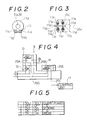
- Fig.1 is a control block diagram for showing an example of a complex machining machine tool to which the present invention is applied;
- Fig.2 is a view in the direction of the arrow II in a clamping unit portion in Fig.1;
- Fig.3 is a plan view of Fig.2;
- Fig.4 is a hydraulic circuit diagram for showing details of a hydraulic power switching unit;
- Fig.5 is a chart for showing the control sequence of each valve;
- Fig.6 is a flowchart for showing an example of clamp control program;
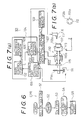
- Fig.7 (a) is a control block diagram for showing an example of a complex machining machine tool to which the present invention is applied and (b) is a view for showing an example of a workpiece end face to be machined;
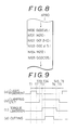
- Fig.8 is a chart for showing an example of machining program;
- Fig.9 is a timing chart for showing the timing of each control movement;
- Fig.10 is a chart for showing an example of a machine tool to which an example of a rotation shaft control unit for machine tool is applied;
- Fig.11 is a diagram for showing an example of hydraulic circuit of a rotation shaft control unit as shown in Fig.10; and
- Fig.12 is a chart for showing a hydraulic power decision table stored in hydraulic power decision table memory of a rotation axis control unit for machine tool.
- A complex
machining machine tool 1 has anNC unit 2 as shown in Fig.1. Amain control portion 3 is provided for theNC unit 2. Aprogram memory 5, ashaft control portion 4, a clampingunit control portion 6 and the like are provided for themain control portion 3. A parameter memory 7 and a hydraulicpower switching unit 9 connet with the clampingunit control portion 6 and ahydraulic power source 10, such as a hydraulic pump, and aclamping unit 11 connect with the hydraulicpower switching unit 9. - The hydraulic
power switching unit 9 has apressure reducing valve 12, afirst solenoid valve 13, asecond solenoid valve 15 and the like as shown in Fig.4. The hydraulicpower switching unit 9 connects with thehydraulic power source 10 on the side of thepressure reducing valve 12 and with theclamping unit 11 on the side of thesecond solenoid valve 15. Theclamping unit 11 has abrake disc 11a fixed in a workpiece spindle described later as shown in Figs.2 and 3. Twoclamping units brake disc 11a in the shape of inserting thebrake disc 11a between both sides of each unit. Thebody 11b is U-formed as shown in Fig.1. Twohydraulic cylinders 11c are provided for eachbody 11b in the shape of inserting thebrake disc 11a between them. Abrake friction pad 11d is provided for eachhydraulic cylinder 11c being free to contact to thebrake disc 11a. - A
spindle motor controller 16 connects with theshaft control portion 4. Aspindle motor 17 connects with thespindle motor controller 16. Anoutput shaft 17a is provided for thespindle motor 17 being directly connected with aworkpiece spindle 19. Aturning angle detector 20 connected with thespindle motor controller 16 is installed in the output shaft 17a. And, achuck 22 is installed in theworkpiece spindle 19. Thechuck 22 can hold theworkpiece 23. Alubricating device 21 connects with theclamping unit 11 in the shape of supplying thebrake disc 11a with lubricating oil. - With the above-described constitution of the complex
machining machine tool 1, in case where usual turning is performed toward aworkpiece 23, thespindle motor 17 is rotated at a predetermined rotational number in the state of holding theworkpiece 23 by thechuck 22 as shown in Fig.1 and a predetermined machining is performed toward theworkpiece 23 by means of turning tool such as a cutting tool. In case where machining is performed with C-axis control and theworkpiece spindle 19 is clamped by theclamping unit 1 positioning at a predetermined angle, themain control portion 3 reads out a clamp control program CPR from theprogram memory 5 and drives and controls theclamping unit 11 on the basis of the clamp control program CPR. - That is, the
first solenoid valve 13 and thesecond solenoid valve 15 of the hydraulicpower switching unit 9 are both changed from "off condition" to "on condition" at the step S1 according to the clamp control porgram CPR as shown in Fig.6. Then, thepressure reducing valve 12 reduces the pressure of pressure oil from thehydraulic power source 10 to a predetermined pressure. And, eachhydraulic cylinder 11c of theclamping unit 11 is supplied with the reduced pressure oil via aline 25A, thefirst solenoid valve 13, aline 25B, thesecond solenoid valve 15 and aline 25C. Eachhydraulic cylinder 11c is supplied with pressure oil in which the pressure is reduced by thepressure reducing valve 12. Then, eachhydraulic cylinder 11c slowly moves thebrake friction pad 11d in the direction of thebrake disc 11a to start contact with thebrake disc 11a. - The clamping
unit control portion 6 keeps thefirst solenoid valve 13 and thesecond solenoid valve 15 ON up to the passage of predetermined time at the step S2 of the clamp control program CPR and waits till all thebrake friction pads 11d of fourhydraulic cylinders 11c of the clampingunit 11 come into contact with thebrake disc 11a. Then, fourbrake friction pads 11d comes into contact with thebrake disc 11a slowly. Therefore, although small time difference results from assembly error and the like in the timing of the start of contact, fourbrake friction pads 11d are contacted with thebrake disc 11a in an equal condition after the passage of predetermined time. Moreover, since thebrake disc 11a is always supplied with lubricating oil from the lubricatingdevice 21, the coefficient of friction between thebrake friction pad 11d and thebrake disc 11a is sharply lowered by the action of lubricating oil. And, in case where by unbalanced contacts of thebrake friction pads 11d, torque acts so that thebrake disc 11a may rotate in either direc tion, there is considerable reduction in the torque. Therefore, there can be few position shear in case of clamping. And, theoutput shaft 17a, that is, theworkpiece shaft 19 is in the state of being free to move without difficulty by the action of lubricating oil until fourbrake friction pads 11d come into contact with thebrake disc 11a with predetermined pressure. On the assumption that theworkpiece spindle 19 shifts to some angles owing to the unbalanced contacts of thebrake friction pads 11d, thespindle motor controller 16 immediately drives thespindle motor 17 in the correcting direction toward the shear according to the turning angle detecting signal S1 from the turningangle detector 20. Accordingly, the shear owing to the unbalanced contacts of thebrake friction pads 11d is corrected and theworkpiece spindle 19 is clamped by the clampingunit 11. - When the
brake disc 11a is slowly clamped by fourhydraulic cylinders 11c in this way, the clamp control program CPR proceeds to the step S3 and thefirst solenoid valve 13 is switched from ON to OFF. Then, eachhydraulic cylinder 11c of the clampingunit 11 is supplied with the pressure oil from thehydraulic power source 10 with the pressure oil highly pressured via theline 25D, thefirst solenoid valve 13, theline 25B, thesecond solenoid valve 15 and theline 25C without via thepressure reducing valve 12. Eachhydraulic cylinder 11c transfers from the clamping of thebrake disc 11a with low pressure to the clamping with high pressure. Thebrake disc 11a is certainly held by fourbrake friction pads 11d (the step S4 of the clamp control program CPR). - When the
workpiece spindle 19 is held by the clampingunit 11 in this way, a predetermined machining is performed toward aworkpiece 23 held by thechuck 22 by means of a turning tool (the step S5 of the clamp control program CPR). On this occasion, since theworkpiece 23 is correctly positioned at a predetermined angular position on C-axis, machining is performed with high accuracy. - When machining finishes, the
second solenoid valve 15 of the hydraulicpower switching unit 9 is switched from ON to OFF to drain the pressure oil of the clampingunit 11. Then, thebrake friction pad 11d of eachhydraulic cylinder 11c leaves thebrake disc 11a by the action of an built-inretaining spring 11e. Thespindle motor 17, that is, theworkpiece spindle 19 is in a state of being free to rotate. - The clamp power of the clamping
unit 11 according to ON-OFF state of the first solenoid valve (SOL1) 13 and the second solenoid valve (SOL2) 15 of the hydraulicpower switching unit 9 is shown in Fig.5. - The above-described embodiments are about a machine tool in which the
workpiece spindle 19 is directly connected with thespindle motor 17. However, in the present invention, any machine tool is available as well as a directly-connected type machine tool as described heretofore. - Another embodiments of the present invention will be explained according to Figs.7 through 9 hereinafter.
- A complex
machining machine tool 101 has amain control portion 102 comprising anNC unit 104 as shown in Fig.7 (a). Amachining program memory 103, ashaft control portion 105, a clampingunit control portion 106 and the like connect with themain control portion 102. A workpiecespindle motor controller 107 connects with theshaft control portion 105 and aparameter memory 109 and aworkpiece spindle motor 110 connect with the workpiecespindle motor controller 107. Aclamping unit 111 connects with the clampingunit control portion 106. - The
workpiece spindle motor 110 has an output shaft formed in the shape of being united as aworkpiece spindle 110a. Achuck 113 for holding aworkpiece 112 to be machined is installed in the right edge portion of theworkpiece spindle 110a in the figure. A turningangle detector 115 is provided at the left edge portion of theworkpiece spindle 110a in the shape of being connected with the workpiecespindle motor controller 107. Aclamp disc 111a comprising theclamping unit 111 is fixed on theworkpiece spindle 110a. Atool rest 116 is provided on the right side of thechuck 113 in Fig.7 being movable and drivable in X-axis and Z-axis directions. Turningtools 117 such as a milling cutter and a drill are attachably and detachably installed in thetool rest 116. - With the above-described constitution of the complex
machining machine tool 101, in case where drill holes 112b are formed at anend face 112a of theworkpiece 112 installed in thechuck 113 at a predetermined angle pitch by means of theturning tool 117 such as a drill as shown in Fig.7 (b), themain control portion 102 reads out a machining program XPRO corresponding to theworkpiece 112 from themachining program memory 103 and machining is performed toward theworkpiece 112 on the basis of the command of the machining program XPRO. That is, in the machining program XPRO, it is commanded to position to the C-axis position, ϑ = 45° by rapid feeding at the step of N100 which is sequence number as shown in Fig.8 (G00C45). Theshaft control portion 105 performs C-axis control toward theworkpiece spindle motor 110 via the workpiecespindle motor controller 107 according to the command to position theworkpiece spindle 110a at the position, ( ϑ = 45°) at which thedrill hole 112b is formed at first. This operation is executed between time T1 and T2 in a timing chart of C-axis movement as shown in Fig.9 (a). - When C-axis is positioned at the position, ϑ= 45° at the time T2 in this way, the machining program outputs a control code M210 at the sequence number N101 and commands the clamping
unit control portion 106 to clamp theworkpiece spindle 110a. Then, the clampingunit control portion 106 drives theclamping unit 111 to clamp theworkpiece spindle 110a positioned at the position, ϑ = 45° by clamping theclamp disc 111a (time T23 in Fig.9(b) ). On this occasion, the clamp power of theclamping unit 111 is controlled according to the clamp control program CPR as shown in Fig.6 as described before to clamp theworkpiece spindle 110a. When theworkpiece spindle 110a is clamped at the C-axis position, ϑ = 45° by theclamping unit 111 in this way, a clamp finishing signal XS1 is outputted to theshaft control portion 105. Receiving this, theshaft control portion 105 commands the workpiecespindle motor controller 107 to limit the torque of theworkpiece spindle motor 110. The workpiecespindle motor controller 107 receives this command, reads out a clamp current value XCT from theparameter memory 109 and limits the upper bound of driving current of theworkpiece spindle motor 110 on the basis of the clamp current value XCT (Fig.9 (c) time T3). The clamp current value XCT is about 5 per cent of the current value corresponding to rating torque. Therefore, the torque of theworkpiece spindle motor 110 is considerably limited in comparison with one in usual condition. - When the
workpiece spindle motor 110 is positioned so that theworkpiece spindle 110a may be ϑ= 45°, theworkpiece spindle 110a oscillates bit by bit with ϑ= 45° as a center in the shape of being corrected so that ϑ = 45° by servo positioning error. And, theworkpiece spindle 110a is held in the shape of shifting in ± direction of C-axis to some degree (a few pulses) in comparison with ϑ = 45° according to the clamping timing of theclamping unit 111. However, even in this clamp condition, a position servo loop comprised of theturning angle detector 15, the workpiecespindle motor controller 107 and theworkpiece spindle motor 110 function as usual. And, the C-axis position of theworkpiece spindle 110a is always detected from the turningangle detector 115 and outputted to the workpiecespindle motor controller 107 as a position signal XS2. Driving current is flowed to theworkpiece spindle motor 110 by the workpiecespindle motor controller 107 so as to correct the error between the position signal XS2 and ϑ= 45° which is command value. As long as the error doesn't shrink between the signal XS2 and the command value, the workpiecespindle motor controller 107 controls so as to increase driving current. However, in case of clamping of theworkpiece spindle 110a by theclamping unit 111, the upper bound of driving current is considerably limited by the clamp current value XCT as described before. Therefore, even if the workpiecespindle motor controller 107 increases driving current to theworkpiece spindle motor 110, there is no possibility of increasing it more than the clamp current value XCT. In result, excessive torque doesn't act on theworkpiece spindle motor 110 and theworkpiece spindle motor 110 doesn't overheat. - The
shaft control portion 105 drives thetool rest 116 according to sequence numbers N102, N103 of the machining program as shown in Fig.8 in such a state the torque of theworkpiece spindle motor 110 is limited between time T3 and T45 in Fig.9 (c). And, machining is performed toward theworkpiece 112 in order to form thedrill hole 112b at the position, ϑ= 45° (between time T34 and T4 in Fig.9 (d) ). - When the machining of the
drill hole 112b finishes by means of theturning tool 117 in this way, theshaft control portion 105 commands the workpiecespindle motor controller 107 to release the limitation of torque. Theworkpiece spindle motor 110 releases the setting of the clamp current value XCT used theretofore at time T45 and theworkpiece spindle motor 110 is recovered in an usual condition. The machining program XPRO proceeds to sequence number N104 as shown in Fig.8. The clampingunit control portion 106 unclamps theclamping unit 111 according to the control code of M212 and releases the clamping condition of the workpiece spindle 110a (time T5 in Fig.9 (b) ). When an unclamping signal XS3 is outputted to theshaft control portion 105 for indicating the release of the clamping of theworkpiece spindle 110a, theshaft control portion 105 proceeds to sequence number N1O5 of the machining program XPRO and proceeds to rapid feeding and positioning movements in order to position theworkpiece spindle 110a, that is, theworkpiece 112 at the C-axis position ϑ= 135° to be machined toward thedrill hole 112b (time T6 in Fig.9 (a) ). On this occasion, since theworkpiece spindle motor 110 is driven in such a state that the limitation by the clamp current value XCT is released, rapid feeding and positioning movements are smoothly performed. Even on the occasion of the clamping of theworkpiece spindle 110a by theclamping unit 111, the servo loop of theworkpiece spindle motor 110 continues to work via theturning angle detector 115 and the workpiecespindle motor controller 107. Accordingly, the workpiecespindle motor controller 107 always recognizes the present position of C-axis of theworkpiece spindle 110a. Therefore, it is possible to proceed to next C-axis positioning movement immediately without origin recovering movement when theclamping unit 111 is unclamped. - In case where usual turning is performed by using the complex
machining machine tool 101, theworkpiece spindle motor 110 is rotated at a predetermined rotation number and theworkpiece 112 held by thechuck 113 is machined by tools for turning on thetool rest 116. - Moreover, an example of rotation axis control unit for machine tool will be explained according to Figs. 10 through 12 hereinafter.
- A
machine tool 201 capable of performing C-axis control, such as a lathe has arotation shaft 202, a drivingmotor 203, anNC unit 205, a rotationshaft control unit 206 and the like as shown in Fig.10. TheNC unit 205 has amain control portion 207. A data input-output unit 210, aconsole panel 211, an input-output control portion 212, amachining data memory 215, a cuttingtype discriminating portion 213 comprising the rotationshaft control unit 206, a hydraulic powerdecision table memory 216, an operatingportion 217 and the like connect with themain control portion 207 via abus line 209. A rotationshaft motor controller 219 and a hydraulicpower switching unit 220 comprising the rotationshaft control unit 206 connect with the input-output control portion 212. A hydraulic power switching table ZT1 as shown in Fig.12 is stored in the hydraulic powerdecision table memory 216. The kinds of hydraulic power switching signals ZS (for instance, ZS1, ZS2, ZS3, ZS4) which is outputted to the hydraulicpower switching unit 220 as shown in Fig.10 ac cording to cutting types CV (for instance, CV1, CV2, CV3) are written in the hydraulic power switching table ZT1. Ahydraulic power source 221 compounding from a hydraulic pump, a drain tank and the like connects with the hydraulicpower switching unit 220. - The
rotation shaft 202, such as a spindle is provided viabearings rotation shaft 202 via a chuck (not shown). At the center portion of therotation shaft 202 in the figure, the drivingmotor 203 is provided in the shape of being built in therotation shaft 202. The rotationshaft motor controller 219 described before connects with the drivingmotor 203. And, adisc 223a comprising apublic disc brake 223 is installed in the left edge portion of therotation shaft 202 in the figure. An engagingunit 223b comprising thedisc brake 223 is provided below therotation shaft 202 in the figure so as to be able to hold thedisc 223a with predetermined power by means ofpads unit 223b. The hydraulicpower switching unit 220 described before connects with the engagingunit 223b. - The hydraulic
power switching unit 220 has a firstdirectional control valve 220a, a seconddirectional control valve 220b, a thirddirectional control valve 220c, a firstpressure reducing valve 220d, a second pressure reducing valve 220e, and the like as shown in Fig.11. The firstpressure reducing valve 220d connects with the firstdirectional control valve 220a via aline 220h. A hydraulic pump (not shown) comprising thehydraulic power source 221 as shown in Fig.10 connects with the firstpressure reducing valve 220d via aline 220f. The hydraulic pump directly connects with the firstdirectional control valve 220a as shown in Fig.11 via theline 220f. And, the second pressure reducing valve 220e connects with the firstdirectional control valve 220a via aline 220i and the seconddirectional control valve 220b connects with the second pressure reducing valve 220e via a line 220j. - The second
directional control valve 220b directly connects with the firstdirectional control valve 220a via theline 220i. And, the thirddirectional control valve 220c connects with the seconddirectional control valve 220b via aline 220k. A drain tank (not shown) comprising thehydraulic power source 221 as shown in Fig.10 connects with the thirddirectional control valve 220c via aline 220g. And, the engagingunit 223b of thedisc brake 223 as shown in Fig.10 connects with the thirddirectional control valve 220c as shown in Fig.11 via aline 220m. - With the above-described constitution of the
machine tool 201, in order to perform milling with C-axis control toward a workpiece by using themachine tool 201, a workpiece (not shown) to be machined is installed in therotation shaft 202 as shown in Fig.10 through a chuck and the like. In this state, a worker inputs machining data ZD1 (for instance, the X-axis coordinate values X1, X2 of the machining starting point and the machining end point of a workpiece in the directions as shown by the arrows C and D (X-axis direction) in Fig.10, the angular velocity V of therotation shaft 202 and the like) via the data input-output unit 210 of theNC unit 205. Then, the data input-output unit 210 outputs those machining data ZD1 to themachining data memory 215. Receiving this, themachining data memory 215 stores the machining data ZD1 as a part of a machining program ZPRO. - When the machining program ZPRO is composed and stored in the
machining data memory 215 in this way, a worker inputs a machining starting command ZSC1 via theconsole panel 211 as shown in Fig.10. Receiving this, themain control portion 207 commands the operatingportion 217 to compose an executable program ZPRO1 including the generation of tool path. Then, the operatingportion 217 reads out the machining program ZPRO stored in themachining data memory 215 and composes the executable program ZPRO1 on the basis of EIA-ISO code and the like according to the program ZPRO. And, milling and the like are performed with C-axis control toward a workpiece according to the composed executable program ZPRO1. - That is, at first, the
main control portion 207 of theNC unit 205 as shown in Fig.10 outputs any indexing command ZSR to the rotationshaft motor controller 219 via the input-output coutrol portion 212 as shown in Fig.10 so that therotation shaft 202 may be positioned at the position with predetermined angle to C-axis origin (C-axis origin is not shown) in order to execute the steps of the executable program ZPRO1 composed by the operatingportion 217 in order. Then, the rotationshaft motor controller 219 rotates the driving motor 203 (that is, the rotation shaft 202) at a predetermined angular velocity V in the directions as shown by the arrows ZA and ZB with rotation angle quantity ϑ to position therotation shaft 202 at the position with a predetermined angle to C-axis origin. - In case where the
main control portion 207 as shown in Fig.10 outputs the indexing command ZSR to the rotationshaft motor controller 219, the cuttingtype discriminating portion 213 reads out the executable program ZPRO1 from the operatingportion 217 and determines that the cutting type CV to be performed from now on is CV3 as shown in Fig.12, that is, (3) "indexing in no load only" from the contol code of the step indicated by the program ZPRO1. And, the cuttingtype discriminating portion 213 as shown in Fig.10 reads out the hydrulic power decision table ZT1 from the the hydraulic powerdecision table memory 216 and outputs the hydraulic power switching signal ZS4 corresponding to (3) "indexing in no load only", that is, in case where the cutting type CV is CV3, to the hydraulicpower switching unit 220 as shown in Fig.10 by retrieving the read hydraulic power decision table ZT1 as shown in Fig.12. - On this occasion, the hydraulic power switching signals ZS corresponding to the cutting types CV are indicated in the the hydraulic power decision table ZT1 as shown in Fig.12. In case where the cutting type CV is CV1, that is, (1) "cutting with the rotation shaft fixed", ZS1 is indicated as the hydraulic power switching signal ZS according to the cutting type CV. In case where the cutting type CV is CV2, that is, (2) "cutting with the rotation shaft rotating" and A."rough machining (long depth of cut)" F1, ZS2 is indicated as the hydraulic power switching signal ZS according to the cutting type CV. In case where the cutting type CV is CV2, that is, (2) "cutting with the rotation shaft rotating" and B."finishing machining (short depth of cut)" F2, ZS3 is indi cated as the hydraulic power switching signal ZS according to the cutting type CV. And, in case where the cutting type CV is CV3, that is, (3) "indexing in no load only", ZS4 is indicated as the hydraulic power switching signal ZS according to the cutting type CV. Accordingly, the cutting
type discriminating portion 213 can obtain the hydraulic power switching signal ZS according to the determined cutting type CV by retrieving the hydraulic power decision table ZT1. - Then, the hydraulic
power switching unit 220 as shown in Fig.10 stops the drive of all of the first, second and thirddirectional control valves lines directional control valves unit 223b of thedisc brake 223 as shown in Fig.10 isn't supplied with pressure oil from theline 220f (Accordingly, the pressure value ZP of pressure oil supplying the engagingunit 223b is ZP4 (= 0) ). Therefore, thepads unit 223b don't hold thedisc 223a. In result, the indexing of therotation shaft 202 on the basis of the executable program ZPRO1 is performed with high speed and high accuracy since the rotation of therotation shaft 202 in the directions as shown by the arrows ZA and ZB isn't limited by thedisc brake 223 and therotation shaft 202 is directly rotated and driven by the drivingmotor 203 without a speed reducer. - In case where milling is performed toward a workpiece with C-axis control with the
rotation shaft 202 fixed after indexing operation in order to form a key way and the like on a workpiece, themain control portion 207 as shown in Fig.10 commands a tool rest control portion (not shown) to cut a workpiece with therotation shaft 202 fixed on the basis of the executable program XPRO1. When the command is outputted to a tool rest control portion and the like, the cuttingtype discriminating portion 213 determines that the cutting type CV to be performed from now on is CV1 as shown in Fig.12, that is, (1)"cutting with therotation shaft 202 fixed" on the basis of the executable program ZPRO1 read out from the operatingportion 217. Furthermore, the cuttingtype discriminating portion 213 as shown in Fig.10 obtains the hydraulic power switching signal ZS corresponding to the determined cutting type CV1, that is, ZS1 by retrieving the hydraulic power decision table ZT1 read out from the hydraulic powerdecision table memory 216 as shown in Fig.12 and outputs the obtained hydraulic power switching signal ZS1 to the hydraulicpower switching unit 220 as shown in Fig.10. - Then, the hydraulic
power switching unit 220 drives the thirddirectional control valve 220c among the first, second and thirddirectional control valves directional control valve 220c is supplied with pressure oil in which the pressure value ZP is the set value ZP1 from a hydraulic pump via theline 220f, the firstdirectional control valve 220a, theline 220i, the seconddirectional control valve 220b and theline 220k. On this occasion, the pressure value ZP doesn't reduce and the set value ZP1 is kept since the pressure oil supplied to the thirddirectional control valve 220c doesn't pass the first and secondpressure reducing valves 220d and 220e. Then, the engagingunit 223b of thedisc brake 223 as shown in Fig.10 holds thedisc 223a with strong power corresponding to the pressure value ZP1 of the supplied pressure oil via thepads unit 223b is controlled by the clamp control program CPR as shown in Fig.6 to clamp therotation shaft 202 as explained before.) to improve the self-holding function of therotation shaft 202. - Even if cutting power considerably acts on the
rotation shaft 202 by performing milling (heavy cutting in particular) toward a workpiece by means of a tool rest (not shown) in such a manner that the tool rest is moved and driven via a tool rest control portion and the like in the right and left directions in Fig.1 and in the directions as shown by the arrows C and D with therotation shaft 202 fixed, there is no possibility of rotating therotation shaft 202 in the directions as shown by the arrows ZA and ZB by the cutting power. For this reason, the workpiece is cut without chatter and a key way and the like are formed on the workpiece with high accuracy. - In case where a workpiece is cut rotating the
rotation shaft 202 in the directions as shown by the arrows ZA and ZB by C-axis control in order to form a cam groove and the like on a workpiece, themain control portion 207 as shown in Fig.10 commands the rotationshaft motor controller 219, a tool rest control portion and the like to cut a workpiece rotating therotation shaft 202 by C-axis control according to the executable program ZPRO1. When the command is outputted to the tool rest control portion and the like, the cuttingtype discriminating portion 213 determines on the basis of the step relating the cutting movement to be performed from now on which is written in the executable program ZPRO1 that the cutting type CV is CV2 as shown in Fig.12, that is, (2)"cutting with therotation shaft 202 rotating" and A."rough machining (long depth of cut)" F1. And, the cuttingtype discriminating portion 213 obtains the hydraulic power switching signal ZS2 corresponding to the determined cutting type CV2 (A. "rough machining (long depth of cut)" ) by retrieving the hydraulic power decision table ZT1 as shown in Fig.12 and outputs the obtained switching signal ZS2 to the hydraulicpower switching unit 220 as shown in Fig.10. - Then, the hydraulic
power switching unit 220 as shown in Fig.10 drives the first and thirddirectional control valves directional control valves directional control valve 220a connects between thelines directional control valve 220c connects between thelines pressure reducing valve 220d via theline 220f to reduce the presuure value up to ZP2 (<ZP1). Furthermore, in this state, the pressure oil in which the pressure value ZP is ZP2 is inflowing from the firstpressure reducing valve 220d into the thirddirectional control valve 220c via theline 220h, the firstdirectional control valve 220a, theline 220i, the seconddirectional control valve 220b and theline 220k without via the pressure reducing valve 220e. And, the engagingunit 223b of thedisc brake 223 as shown in Fig.10 is supplied with the pressure oil in which the pressure value ZP is ZP2 via the thirddirectional control valve 220c and theline 220m. Then, the engagingunit 223b holds thedisc 223a according to the pressure value ZP2 of the supplied pressure oil with more weak power in comparison with the case of cutting with therotation shaft 202 fixed as described before. For this reason, the rotation of therotation shaft 202 in the directions as shown by the arrows ZA and ZB is limited by thedisc brake 223 to improve self-holding function. - In result, there is no possibility of rotating the
rotation shaft 202 in the directions as shown by the arrows ZA and ZB inadvertently by the considerable cutting power acting on therotation shaft 202 on the assumption that rough machining is performed toward a workpiece by means of the tool installed in a tool rest rotating therotation shaft 202 in the direction as shown by the arrows ZA and ZB by C-axis control in such a state the the depth of cut is long. - In case where finishing machining is further performed toward a workpiece rotating the
rotation shaft 202 after rough machining is performed toward a workpiece rotating therotation shaft 202 by C-axis control, themain control portion 207 as shown in Fig.10 commands the rotationshaft motor controller 219 and the like to perform machining such as milling rotating therotation shaft 202 according to the executable program ZPRO1. Then, the cuttingtype discriminating portion 213 determines on the basis of the executable program ZPRO1 read out from the operatingportion 217 that the cutting type CV to be performed from now on is CV2 as shown in Fig.12, that is, (2) "cutting with therotation shaft 202 rotating" and B "finishing machining (short depth of cut) F2 and obtains the hydraulic power switching signal ZS corresponding to the cutting type CV2 (B "finishing machining (short depth of cut) ), that is, ZS3 by retrieving the hydraulic power decision table ZT1 as shown in Fig.12 to output to the hydraulicpower switching unit 220 as shown in Fig.10. - Then, the
hydraulic switching unit 220 drives the second and thirddirectional control valves directional control valves directional control valve 220b connects between thelines 220j and 220k and the thirddirectional control valve 220c connects between thelines line 220f, the firstdirectional control valve 220a and theline 220i without via thepressure reducing valve 220d to reduce the pressure value ZP up to ZP3 (< ZP2). Moreover, the pressure oil in which the pressure value ZP becomes ZP3 is inflowing from the second pressure reducing valve 220e into the thirddirectional control valve 220c via the line 220j, the seconddirectional control valve 220b and theline 220k. And, the engagingunit 223b of thedisc brake 223 as shown in Fig.10 is supplied with the pressure oil in which the pressure value ZP is ZP3 via the thirddirectional control valve 220c and theline 220m. - Then, the engaging
unit 223b holds thedisc 223a with more weak power in comparison with the case of rough machining as described before according to the pressure value ZP3 of the supplied pressure oil to improve the self-holding function of therotation shaft 202. In result, there is no possibility of rotating therotation shaft 202 in the directions as shown by the arrows ZA and ZB by the cutting power acting on therotation shaft 202 on the assumption that finishing machining is performed toward a workpiece by means of a tool installed in a tool rest rotating therotation shaft 202 so that the depth of cut may be short. Therefore, a cam groove and the like are formed on a workpiece with high accuracy. On this occasion, since the depth of cut F is short and the cutting power acting on therotation shaft 202 is more weak in comparison with in the case of the rough machining as described before, the power to hold thedisc 223a of the engagingunit 223b is weakened. - With such a constitution that brake means such as
disc brake 223 is provided for therotation shaft 202 and brake driving control means such as the hydraulicpower switching unit 220 is provided in order to drive and control said brake means, brake driving control means drives and controls brake means according to machining to be performed from now on to be able to change the power to hold therotation shaft 202 by brake means. - In case where milling and the like are performed toward a workpiece installed in the
rotation shaft 202 rotating therotation shaft 202 by C-axis control, therefore, a workpiece can be machined with high accuracy without chatter in such a manner that brake means is driven and controlled according to the machining contents to change the self-holding function of therotation shaft 202 by stages. And, in case of the indexing of therotation shaft 202, indexing can be performed with high speed and high accuracy by rotating and driving the drivingmotor 203 directly connected with therotation shaft 202 with high speed without holding therotation shaft 202 by brake means. - The present invention is explained according to embodiments hereinbefore. But the embodiments described in the present specification are not restricted but exemplified ones. And, the range of the invention is supported by the attached claims and not bound by the description of the embodiments. Accordingly, all of deformations and changes belonging to the claims is in the range of the present invention.
Claims (14)
- (1). A workpiece spindle control unit in a machine tool having a workpiece spindle, comprising;
a clamping means having plural brake means capable of clamping a rotation of the workpiece spindle, which is provided for the workpiece spindle; and
a clamp power adjusting means capable of change a clamp power of the clamping means by steps provided for said clamping means. - (2). A workpiece spindle control unit according to claim 1 wherein the supply means of friction reducing fluid is connected with said clamping means.
- (3). A workpiece spindle control unit according to claim 1 wherein a spindle motor is directly connected with said workpiece spindle.
- (4). A workpiece spindle control unit according to claim 1 wherein said clamping means has a brake disc installed in the workpiece spindle and the brake means provided in the shape of holding the brake disc between both sides.
- (5). A workpiece spindle control unit according to claim 1 wherein said clamp power adjusting means has a pressure switching means of actuation fluid and said brake means is connected with said pressure switching means in the shape of being free to supply with said actuation fluid.
- (6). A workpiece spindle control unit according to claim 3 wherein a workpiece spindle angle positioning control means is connected with said spindle motor.
- (7). A workpiece spindle control unit according to claim 1 wherein a clamp control means is provided in order to time the acting time of said clamping means and to drive and control said clamp power adjusting means according to the timing result.
- (8). A workpiece spindle control method in a machine tool having a workpiece spindle, comprising;
providing a clamping means having plural brake means capable of clamping a rotation of the workpiece spindle for said workpiece spindle;
contacting with the first clamp power until all brake means is contacted with a workpiece spindle when a workpiece spindle is clamped in case of spindle control; and
contacting with the second clamp power stronger than said first clamp power after said all brake means is contacted with a workpiece spindle. - (9). A workpiece spindle control method according to claim 8 wherein said clamping means is supplied with friction reducing fluid for reducing the clamp power of the clamping means in case where the clamping means clamps the workpiece spindle with the first clamp power.
- (10). A workpiece spindle control method in a machine tool having a workpiece spindle, comprising;
providing a clamping means having plural brake means capable of clamping a rotation of the workpiece spindle for said workpiece spindle;
clamping said workpiece spindle with the first clamp power by working said clamping means when the workpiece spindle is clamped in case of spindle control; and
clamping said workpiece spindle in said clamping means with the second clamp power stronger than said first clamp power after the passage of predetermined time from working start of said clamping means. - (11). A workpiece spindle control method according to claim 10 wherein said clamping means is supplied with friction reducing fluid to reduce the clamp power of the clamping means in case where the workpiece spindle is clamped with the first clamp power.
- (12). A workpiece spindle control unit in a machine tool having a workpiece spindle and a workpiece spindle motor directly connected with the workpiece spindle, a turning angle detecting means for detecting the turning angle of the workpiece spindle provided for said workpiece spindle and a servo control means for controlling the spindle turning angle of said workpiece spindle motor according to the signal from the turning angle detecting means, comprising;
a clamping means for clamping said workpiece spindle; and
a command means for commanding said servo control means to reduce the torque of the workpiece spindle motor in comparison with an usual rating torque while the clamping means is clamping the rotation of the workpiece spindle. - (13). A workpiece spindle control method in a machine tool having a workpiece spindle and a workpiece spindle motor directly connected with the workpiece spindle, a turning angle detecting means for detecting the turning angle of the workpiece spindle provided for said workpiece spindle and a servo control means for controlling the spindle turning angle of said workpiece spindle motor according to the signal from the turning angle detecting means, comprising;
providing a clamping means for clamping said workpiece spindle;
clamping the workpiece spindle together with the workpiece spindle motor by driving said clamping means and continuing to control the workpiece spindle motor by said servo control means when a workpiece spindle is fixed at a predetermined angular position in case of spindle control; reducing the torque of the workpiece spindle motor in comparison with an usual rating torque; and
preventing the overheat of the workpiece spindle motor. - (14). A workpiece spindle control method in a machine tool having a workpiece spindle and a workpiece spindle motor directly connected with the workpiece spindle, a turning angle detecting means for detecting the turning angle of the workpiece spindle provided for said workpiece spindle and a servo control means for controlling the spindle turning angle of said workpiece spindle motor according to the signal from the turning angle detecting means, comprising;
rotating and positioning said workpiece spindle together with a workpiece held by the workpiece spindle at a predetermined angular position by driving and controlling said workpiece spindle motor by means of said servo control means in case where a workpiece is held in the shape of fixing at a predetermined angular position via a workpiece spindle and a predetermined machining is performed toward the held workpiece;
clamping said workpiece spindle when said workpiece spindle is positioned at a predetermined angular position and limiting the torque of said workpiece spindle motor;
performing machining toward said workpiece in this state; and
releasing the limitation of the torque of said workpiece spindle motor and releasing the clamp state of said workpiece spindle when machining finishes toward the workpiece.
Applications Claiming Priority (4)
| Application Number | Priority Date | Filing Date | Title |
|---|---|---|---|
| JP226090/88 | 1988-08-09 | ||
| JP63226090A JPH0276665A (en) | 1988-09-09 | 1988-09-09 | Method and device for controlling work spindle |
| JP63226091A JPH0276666A (en) | 1988-09-09 | 1988-09-09 | Method and device for clamping of spindle |
| JP226091/88 | 1988-09-09 |
Publications (3)
| Publication Number | Publication Date |
|---|---|
| EP0358531A2 true EP0358531A2 (en) | 1990-03-14 |
| EP0358531A3 EP0358531A3 (en) | 1990-10-24 |
| EP0358531B1 EP0358531B1 (en) | 1994-03-02 |
Family
ID=26526984
Family Applications (1)
| Application Number | Title | Priority Date | Filing Date |
|---|---|---|---|
| EP89309165A Expired - Lifetime EP0358531B1 (en) | 1988-09-09 | 1989-09-08 | Workpiece spindle control unit and control method |
Country Status (4)
| Country | Link |
|---|---|
| US (1) | US5107730A (en) |
| EP (1) | EP0358531B1 (en) |
| KR (1) | KR970011786B1 (en) |
| DE (1) | DE68913401T2 (en) |
Cited By (4)
| Publication number | Priority date | Publication date | Assignee | Title |
|---|---|---|---|---|
| DE19503145A1 (en) * | 1994-02-03 | 1995-08-10 | Smc Corp | Positioning device for load e.g. workpiece |
| EP0749803A1 (en) * | 1995-06-22 | 1996-12-27 | Gildemeister Ag | Fixing means for the workpiece spindle of a lathe |
| EP1452266A2 (en) * | 2003-02-26 | 2004-09-01 | DECKEL MAHO Pfronten GmbH | Workpiece holder for elongated work pieces |
| WO2009036918A1 (en) * | 2007-09-14 | 2009-03-26 | Hema Maschinen Und Apparateschutz Gmbh | Clamping and braking system |
Families Citing this family (13)
| Publication number | Priority date | Publication date | Assignee | Title |
|---|---|---|---|---|
| US5730037A (en) * | 1995-04-17 | 1998-03-24 | Logan Clutch Corporation | Multi-spindle machine control systems |
| US5676030A (en) | 1995-08-14 | 1997-10-14 | Crudgington Machine Tools, Inc. | Multi-spindle CNC lathe |
| JP3987380B2 (en) * | 2002-05-31 | 2007-10-10 | ヤマザキマザック株式会社 | Tool holder for turret lathe |
| JP2004034160A (en) * | 2002-06-28 | 2004-02-05 | Yamazaki Mazak Corp | Turret for turret lathe |
| KR100893454B1 (en) * | 2002-09-23 | 2009-04-17 | 두산인프라코어 주식회사 | C-shaft Break System in Turning center maintaining initial position of C-shaft |
| US8083020B2 (en) * | 2008-11-18 | 2011-12-27 | Corriher Ted H | Braking system for front caster wheels of a self-propelled vehicle |
| US8511417B2 (en) | 2008-11-18 | 2013-08-20 | Ted H. CORRIHER | Braking system for front caster wheels of a self-propelled vehicle |
| KR102010590B1 (en) * | 2012-12-24 | 2019-08-13 | 두산공작기계 주식회사 | Spindle clamping and unclamping automatic control device and method thereof |
| JP5887299B2 (en) * | 2013-04-24 | 2016-03-16 | ファナック株式会社 | Rotary table having clamp torque measuring means |
| US9517540B1 (en) * | 2015-09-30 | 2016-12-13 | Inventables, Inc. | Milling machine with a smart clamp for automatically determining the Z origin of a work piece |
| USD775246S1 (en) | 2015-09-30 | 2016-12-27 | Inventables, Inc. | Milling machine |
| CN108098531B (en) * | 2016-11-25 | 2021-08-27 | 南京德朔实业有限公司 | Angle grinder, electric tool and braking method thereof |
| CN113400069B (en) * | 2021-05-06 | 2022-09-13 | 北京科技大学 | Hydraulic double-elastomer deformation type locking device |
Citations (6)
| Publication number | Priority date | Publication date | Assignee | Title |
|---|---|---|---|---|
| DE744429C (en) * | 1939-07-15 | 1944-01-22 | Boehringer Gmbh Geb | Drive for a lathe, especially for machining crankshafts |
| DE6917979U (en) * | 1969-04-30 | 1970-01-22 | Zahnradfabrik Friedrichshafen | DEVICE FOR STOPPING A SHAFT, FOR EXAMPLE, STOPPING THE WORKING SPINDLE OF A MACHINE TOOL |
| DE7102263U (en) * | 1973-11-29 | Heyligenstaedt & Comp Gmbh | Device for setting the work spindle of a numerically steered lathe in a certain angular position | |
| EP0135754A2 (en) * | 1983-08-22 | 1985-04-03 | Kabushiki Kaisha S.G. | Positioning control device for an electric motor |
| DE3621460A1 (en) * | 1985-06-26 | 1987-01-08 | Mitsubishi Electric Corp | TURN BODY POSITION CONTROL UNIT |
| EP0272825A2 (en) * | 1986-12-20 | 1988-06-29 | Wickman Bennett Machine Tool Company Limited | Lathes |
Family Cites Families (3)
| Publication number | Priority date | Publication date | Assignee | Title |
|---|---|---|---|---|
| US4048880A (en) * | 1972-08-08 | 1977-09-20 | Index-Werke Kg Hahn & Tessky | System for supplying hydraulic fluid to aggregates on spindles or the like |
| JPS62193704A (en) * | 1986-02-20 | 1987-08-25 | Hitachi Ltd | Ultra precision lathe |
| US4926723A (en) * | 1988-12-06 | 1990-05-22 | Ralph Earl Co., Inc. | Machine tool auxiliary function hydraulic system |
-
1989
- 1989-09-08 EP EP89309165A patent/EP0358531B1/en not_active Expired - Lifetime
- 1989-09-08 US US07/404,963 patent/US5107730A/en not_active Expired - Lifetime
- 1989-09-08 DE DE68913401T patent/DE68913401T2/en not_active Expired - Lifetime
- 1989-09-09 KR KR1019890013086A patent/KR970011786B1/en not_active IP Right Cessation
Patent Citations (6)
| Publication number | Priority date | Publication date | Assignee | Title |
|---|---|---|---|---|
| DE7102263U (en) * | 1973-11-29 | Heyligenstaedt & Comp Gmbh | Device for setting the work spindle of a numerically steered lathe in a certain angular position | |
| DE744429C (en) * | 1939-07-15 | 1944-01-22 | Boehringer Gmbh Geb | Drive for a lathe, especially for machining crankshafts |
| DE6917979U (en) * | 1969-04-30 | 1970-01-22 | Zahnradfabrik Friedrichshafen | DEVICE FOR STOPPING A SHAFT, FOR EXAMPLE, STOPPING THE WORKING SPINDLE OF A MACHINE TOOL |
| EP0135754A2 (en) * | 1983-08-22 | 1985-04-03 | Kabushiki Kaisha S.G. | Positioning control device for an electric motor |
| DE3621460A1 (en) * | 1985-06-26 | 1987-01-08 | Mitsubishi Electric Corp | TURN BODY POSITION CONTROL UNIT |
| EP0272825A2 (en) * | 1986-12-20 | 1988-06-29 | Wickman Bennett Machine Tool Company Limited | Lathes |
Cited By (7)
| Publication number | Priority date | Publication date | Assignee | Title |
|---|---|---|---|---|
| DE19503145A1 (en) * | 1994-02-03 | 1995-08-10 | Smc Corp | Positioning device for load e.g. workpiece |
| DE19503145C2 (en) * | 1994-02-03 | 2001-10-11 | Smc Corp | Load positioning device |
| EP0749803A1 (en) * | 1995-06-22 | 1996-12-27 | Gildemeister Ag | Fixing means for the workpiece spindle of a lathe |
| EP1452266A2 (en) * | 2003-02-26 | 2004-09-01 | DECKEL MAHO Pfronten GmbH | Workpiece holder for elongated work pieces |
| EP1452266A3 (en) * | 2003-02-26 | 2006-05-17 | DECKEL MAHO Pfronten GmbH | Workpiece holder for elongated work pieces |
| CN100371130C (en) * | 2003-02-26 | 2008-02-27 | 德克尔·马霍普夫龙滕有限责任公司 | Working talbe for processing bar-shape workpieces |
| WO2009036918A1 (en) * | 2007-09-14 | 2009-03-26 | Hema Maschinen Und Apparateschutz Gmbh | Clamping and braking system |
Also Published As
| Publication number | Publication date |
|---|---|
| EP0358531B1 (en) | 1994-03-02 |
| DE68913401T2 (en) | 1994-06-01 |
| US5107730A (en) | 1992-04-28 |
| DE68913401D1 (en) | 1994-04-07 |
| KR970011786B1 (en) | 1997-07-16 |
| EP0358531A3 (en) | 1990-10-24 |
| KR900004454A (en) | 1990-04-12 |
Similar Documents
| Publication | Publication Date | Title |
|---|---|---|
| EP0358531A2 (en) | Workpiece spindle control unit and control method | |
| US8234958B2 (en) | Toolholder | |
| CN102027426B (en) | Method for numerical control and numerical control machine | |
| US4604705A (en) | Numerical control machining method and system therefor | |
| US6742422B1 (en) | Numerically controlled lathe and method of cutting workpiece on the numerically controlled lathe | |
| JPS5959339A (en) | Method of retreating tool from work and returning it to workand numerical controlled machining device executing the me- thod | |
| JPS6332586B2 (en) | ||
| US6971294B1 (en) | Numerically controlled lathe and method of machining work using this numerically controlled lathe | |
| JPH046001B2 (en) | ||
| US5058029A (en) | Setting control method of machining coordinate system in a machine tool | |
| US7055416B2 (en) | Tool holder and method of machining work using this tool holder | |
| JPH0276602A (en) | Complex processing machine tool and its control method | |
| JP2729248B2 (en) | Non-circular lathe | |
| JP2772826B2 (en) | Numerically controlled combined lathe and its machining method | |
| KR100324642B1 (en) | Dual Rotary Table Control Unit and Method | |
| KR20010066642A (en) | Manufacture Exchenge Time Shortening Unit Usig Senser and Method | |
| JPH06262403A (en) | Position control device for moving body in machine tool | |
| EP4245444A1 (en) | Method for controlling superimposed machining of nc machine tool | |
| KR100240935B1 (en) | Home position return control system of automatic tool exchanger | |
| JP2005288612A (en) | Control method of nc machine tool having index table and nc machine tool | |
| JPH10109251A (en) | Method for controlling rotation speed of turret | |
| KR20010078527A (en) | Clamping Pressure Supply Unit of a Structure and Method | |
| EP0314802A1 (en) | High-efficiency tool selection system | |
| JPH0288101A (en) | Work transfer confirmation method for facing type two spindle lathe and control device therefor | |
| JPH0410643B2 (en) |
Legal Events
| Date | Code | Title | Description |
|---|---|---|---|
| PUAI | Public reference made under article 153(3) epc to a published international application that has entered the european phase |
Free format text: ORIGINAL CODE: 0009012 |
|
| AK | Designated contracting states |
Kind code of ref document: A2 Designated state(s): DE ES FR GB IT |
|
| PUAL | Search report despatched |
Free format text: ORIGINAL CODE: 0009013 |
|
| AK | Designated contracting states |
Kind code of ref document: A3 Designated state(s): DE ES FR GB IT |
|
| 17P | Request for examination filed |
Effective date: 19901121 |
|
| 17Q | First examination report despatched |
Effective date: 19911206 |
|
| GRAA | (expected) grant |
Free format text: ORIGINAL CODE: 0009210 |
|
| AK | Designated contracting states |
Kind code of ref document: B1 Designated state(s): DE ES FR GB IT |
|
| PG25 | Lapsed in a contracting state [announced via postgrant information from national office to epo] |
Ref country code: IT Free format text: LAPSE BECAUSE OF FAILURE TO SUBMIT A TRANSLATION OF THE DESCRIPTION OR TO PAY THE FEE WITHIN THE PRE;WARNING: LAPSES OF ITALIAN PATENTS WITH EFFECTIVE DATE BEFORE 2007 MAY HAVE OCCURRED AT ANY TIME BEFORE 2007. THE CORRECT EFFECTIVE DATE MAY BE DIFFERENT FROM THE ONE RECORDED.SCRIBED TIME-LIMIT Effective date: 19940302 Ref country code: ES Free format text: THE PATENT HAS BEEN ANNULLED BY A DECISION OF A NATIONAL AUTHORITY Effective date: 19940302 Ref country code: FR Free format text: THE PATENT HAS BEEN ANNULLED BY A DECISION OF A NATIONAL AUTHORITY Effective date: 19940302 |
|
| REF | Corresponds to: |
Ref document number: 68913401 Country of ref document: DE Date of ref document: 19940407 |
|
| EN | Fr: translation not filed | ||
| PLBE | No opposition filed within time limit |
Free format text: ORIGINAL CODE: 0009261 |
|
| STAA | Information on the status of an ep patent application or granted ep patent |
Free format text: STATUS: NO OPPOSITION FILED WITHIN TIME LIMIT |
|
| 26N | No opposition filed | ||
| REG | Reference to a national code |
Ref country code: GB Ref legal event code: IF02 |
|
| PGFP | Annual fee paid to national office [announced via postgrant information from national office to epo] |
Ref country code: GB Payment date: 20080910 Year of fee payment: 20 |
|
| PGFP | Annual fee paid to national office [announced via postgrant information from national office to epo] |
Ref country code: DE Payment date: 20080919 Year of fee payment: 20 |
|
| REG | Reference to a national code |
Ref country code: GB Ref legal event code: PE20 Expiry date: 20090907 |
|
| PG25 | Lapsed in a contracting state [announced via postgrant information from national office to epo] |
Ref country code: GB Free format text: LAPSE BECAUSE OF EXPIRATION OF PROTECTION Effective date: 20090907 |