EP0356849A2 - Trailer hitch - Google Patents
Trailer hitch Download PDFInfo
- Publication number
- EP0356849A2 EP0356849A2 EP89115330A EP89115330A EP0356849A2 EP 0356849 A2 EP0356849 A2 EP 0356849A2 EP 89115330 A EP89115330 A EP 89115330A EP 89115330 A EP89115330 A EP 89115330A EP 0356849 A2 EP0356849 A2 EP 0356849A2
- Authority
- EP
- European Patent Office
- Prior art keywords
- trailer
- double lever
- joint
- main strut
- coupling
- Prior art date
- Legal status (The legal status is an assumption and is not a legal conclusion. Google has not performed a legal analysis and makes no representation as to the accuracy of the status listed.)
- Withdrawn
Links
Images


Classifications
-
- B—PERFORMING OPERATIONS; TRANSPORTING
- B60—VEHICLES IN GENERAL
- B60D—VEHICLE CONNECTIONS
- B60D1/00—Traction couplings; Hitches; Draw-gear; Towing devices
- B60D1/24—Traction couplings; Hitches; Draw-gear; Towing devices characterised by arrangements for particular functions
- B60D1/36—Traction couplings; Hitches; Draw-gear; Towing devices characterised by arrangements for particular functions for facilitating connection, e.g. hitch catchers, visual guide means, signalling aids
- B60D1/40—Traction couplings; Hitches; Draw-gear; Towing devices characterised by arrangements for particular functions for facilitating connection, e.g. hitch catchers, visual guide means, signalling aids involving a temporarily extensible or alignable member
Definitions
- the invention relates to a central axle trailer in a configuration known from DE-A-37 00 116 according to the preamble of claim 1.
- the invention has for its object to provide a central axle trailer that allows a short attachment to the trailer coupling of a towing vehicle and a change in distance depending on cornering with a structurally particularly simple and robust connection device with clear power transmission in all operating positions.
- the central axle trailer according to the invention is characterized by the features specified in the characterizing part of claim 1. With regard to further refinements, reference is made to claims 2 to 4.
- Dia connecting device of the central axle trailer creates a fully mechanical, to a normal trailer coupling of a towing vehicle short coupling system simple, robust and inexpensive to manufacture design that is not susceptible to malfunctions and ensures proportional power transmission without response delay.
- FIGS. 1 to 3 illustrates in FIGS. 1 to 3 only the front area of the inventive central axis Trailer 1 trained trailer, which is provided for attachment to a towing vehicle 2, which in turn is only schematically illustrated with its rear area, with a connection device designated as a whole by 3.
- the towing vehicle 2 has in its rear area below a loading level a conventional coupling 4 with a vertical coupling axis 5, with which the connecting element 6 of the connecting device 3 can be coupled.
- the connecting device 3 comprises an adjusting device designated as a whole by 7, by means of which the distance of the connecting member 6 from the front end edge 8 of the trailer 1 can be adjusted depending on the turning angle between the towing vehicle 2 and the trailer 1.
- the present at a turning angle of 0 ° minimum distance between the connecting member 6 and the front end edge 8 of the trailer 1 preferably experiences a maximum turning angle-dependent enlargement of 400 mm or more, which ensures that, despite the small bodywork distance between the towing vehicle 2 and the trailer 1, when driving straight ahead Bends - up to a steering angle of 90 °, as is desirable for maneuvering - there are no body contacts.
- FIGS. 1 to 3 with their representation of the position of the vehicle bodies relative to one another at turning angles of 30 °, 60 ° or 90 °.
- the actuating device 7 is designed as a mechanical lever transmission, which comprises a first double lever 9, a second double lever 10 and a link 11.
- This lever mechanism 9, 10, 11 acts on a main strut 12 of the connecting device 3, which is guided in a sliding guide 13 attached to the trailer 1.
- the main strut 12 which is preferably designed as a square tube, is connected at its front end to the first double lever 9 via a first joint 14, the front part of which comprises the connecting member 6.
- the rear end of the first double lever 9 is connected to the second double lever 10 via a second joint 15, the second joint 15 being displaceably guided along the front region of the second double lever 10.
- the second joint 15 is preferably formed by a feeler wheel 17 which is freely rotatable about a bearing journal 16 on the first double lever 9 and which is guided in a longitudinal guideway 18 on the second double lever 10.
- the second double lever 10 is connected between its ends to the main strut 12 via a third joint 19, which is formed by a vertical pivot pin 21 passing through a bearing bush 20, at the upper end of the lever part 22 protruding upwards beyond the main strut 12 in the straight-ahead position of the second double lever 10 and on its lower end, which projects downward beyond the main strut 12 and engages the front lever part 23 of the second double lever 10 in the straight-ahead driving position.
- the second double lever 10 has the basic shape of a Z.
- the second double lever 10 is connected via a fourth joint 24 to the front end of the link 11, which at its rear end is connected to the trailer 1 via a fifth joint 26 on the underside of the sliding guide 13 is.
- the hinge axis 27 of the fifth hinge 26 is oriented vertically, runs in the vertical longitudinal center plane 28 of the trailer 1 and has an orientation parallel to the hinge axes of the joints 14, 15, 19 and 24.
- the first double lever 9 comprises a rear lever part 29, the rear end of which is assigned to the second joint 15, and a front lever part 30 which connects the connecting element 6 and abutment arms 31 arranged on both sides of the connecting element 6 , 32 has.
- the front ends of the abutment arms 31, 32 have stop surfaces 33, 34 defining a support plane, with which they are supported in the attached position of the parts of the connecting device 3 on the towing vehicle 2 on both sides of its coupling 4 and, as a result of this support, the first double lever 9 against horizontal pivoting movements around the Lock clutch axle 5.
- the coupling axis 5 lies at a short distance in front of the support plane defined by the abutment arms 31, 32, but a shortened version is preferred in which the coupling axis 5 coincides with the support plane of the abutment arms 31, 32.
- the first double lever 9 pivots about the first joint 14 (clockwise in FIG. 5), as a result of which the second double lever 10 closes a pivoting movement about the third joint 19 (also clockwise in Fig. 5) is caused.
- the second joint 15 moves along the longitudinal guideway 18 a little towards the rear end of the second double lever 10, as can be seen from a comparison between FIGS. 4 and 5 (or 5 and 6 or 6 and 7) .
- the handlebar 11 also undergoes a pivoting (clockwise in FIG. 5), and by means of this pivoting the main strut 12 can carry out a feed movement in its sliding guide 13, through which the distance between the bodies of the vehicles 1 , 2 enlarged.
- the main strut 12 takes over in its area between the joints 14, 19 pulling and in braking processes also compressive forces and steering forces. In the area between the joint 19 and the joint 26, only steering forces are transmitted from the main strut 12. The transmission of traction or compression force is carried out in this area by the link 11 and the double lever 9, 10.
Abstract
Description
Die Erfindung betrifft einen Zentralachsanhänger in einer aus der DE-A-37 00 116 bekannten Ausbildung gemäß dem Oberbegriff des Anspruchs 1.The invention relates to a central axle trailer in a configuration known from DE-A-37 00 116 according to the preamble of
Der Erfindung liegt die Aufgabe zugrunde, einen Zentralachsanhänger zu schaffen, der eine Kurzanhängung an die Anhängekupplung eines Zugfahrzeugs und eine Abstandsveränderung in Abhängigkeit von Kurvenfahrten mit einer baulich besonders einfachen und robusten Anschlußvorrichtung mit eindeutiger Kraftübertragung in allen Betriebsstellungen ermöglicht.The invention has for its object to provide a central axle trailer that allows a short attachment to the trailer coupling of a towing vehicle and a change in distance depending on cornering with a structurally particularly simple and robust connection device with clear power transmission in all operating positions.
Zur Lösung dieser Aufgabe ist der Zentralachsanhänger nach der Erfindung gekennzeichnet durch die im kennzeichnenden Teil des Anspruchs 1 angegebenen Merkmale. Hinsichtlich weiterer Ausgestaltungen wird auf die Ansprüche 2 bis 4 verwiesen.To achieve this object, the central axle trailer according to the invention is characterized by the features specified in the characterizing part of
Dia Anschlußvorrichtung des Zentralachsanhängers nach der Erfindung schafft ein vollmechanisches, an eine normale Anhängekupplung eines Zugfahrzeugs anschließbares Kurzkuppelsystem einfacher, robuster und preisgünstig herstellbarer Bauart, das unanfällig gegen Betriebsstörungen ist und proportionale Kraftübertragungen ohne Ansprechverzug gewährleistet.Dia connecting device of the central axle trailer according to the invention creates a fully mechanical, to a normal trailer coupling of a towing vehicle short coupling system simple, robust and inexpensive to manufacture design that is not susceptible to malfunctions and ensures proportional power transmission without response delay.
Ein Ausführungsbeispiel des Gegenstands der Erfindung ist in der Zeichnung näher veranschaulicht. Im einzelnen zeigen:
- Fig. 1 eine schematische, abgebrochene Draufsicht auf einen mit einem Einschlagwinkel von 30° einem Zugfahrzeug nachlaufenden Zentralachsanhänger nach der Erfindung,
- Fig. 2 eine Draufsicht ähnlich Fig. 1 mit einem Einschlagwinkel von 60° zwischen Zugfahrzeug und Zentralachsanhänger,
- Fig. 3 eine Draufsicht ähnlich Fig. 1 und 2 mit einem Einschlagwinkel von 90° zwischen Zugfahrzeug und Zentralachsanhänger,
- Fig. 4 eine abgebrochene Draufsicht auf die Anschlußvorrichtung in vergrößerter Einzeldarstellung mit einer Anordnung der Teile bei einem Einschlagwinkel von 0°,
- Fig. 5 eine Draufsicht ähnlich Fig. 4 mit einer Anordnung der Teile bei einem Einschlagwinkel von 30°,
- Fig. 6 eine Draufsicht ähnlich Fig. 4 und 5 mit einer Anordnung der Teile bei einem Einschlagwinkel von 60°,
- Fig. 7 eine Draufsicht ähnlich Fig. 4 bis 6 mit einer Anordnung der Teile bei einem Einschlagwinkel von 90°,
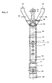
- Fig. 8 einen abgebrochenen vertikalen Längsmittelschnitt durch die Anschlußvorrichtung gemäß Fig. 4, und
- Fig. 9 einen Schnitt nach der Linie IX-IX in Fig. 8.
- 1 is a schematic, broken top view of a central axle trailer following a towing vehicle with a turning angle of 30 °, according to the invention,
- 2 is a plan view similar to FIG. 1 with a turning angle of 60 ° between the towing vehicle and the central axle trailer,
- 3 is a plan view similar to FIGS. 1 and 2 with a steering angle of 90 ° between the towing vehicle and the central axle trailer,
- 4 shows a broken top view of the connection device in an enlarged individual illustration with an arrangement of the parts at a turning angle of 0 °,
- 5 is a plan view similar to FIG. 4 with an arrangement of the parts at a turning angle of 30 °,
- 6 is a plan view similar to FIGS. 4 and 5 with an arrangement of the parts at a turning angle of 60 °,
- 7 is a plan view similar to FIGS. 4 to 6 with an arrangement of the parts at a turning angle of 90 °,
- Fig. 8 is a broken vertical longitudinal section through the connection device according to FIG. 4, and
- 9 shows a section along the line IX-IX in FIG. 8.
Die Zeichnung veranschaulicht in den Fig. 1 bis 3 lediglich den vorderen Bereich des erfindungsgemäßen, als Zentralachs anhänger 1 ausgebildeten Anhängers, der für eine Anhängung an ein Zugfahrzeug 2, das seinerseits lediglich mit seinem rückwärtigen Bereich schematisch veranschaulicht ist, mit einer als Ganzes mit 3 bezeichneten Anschlußvorrichtung versehen ist.The drawing illustrates in FIGS. 1 to 3 only the front area of the inventive
Das Zugfahrzeug 2 weist in seinem rückwärtigen Bereich unterhalb einer Ladeebene eine übliche Kupplung 4 mit vertikaler Kupplungsachse 5 auf, mit der das Anschlußglied 6 der Anschlußvorrichtung 3 kuppelbar ist. Die Anschlußvorrichtung 3 umfaßt eine als Ganzes mit 7 bezeichnete Stellvorrichtung, durch die in Abhängigkeit vom Einschlagwinkel zwischen Zugfahrzeug 2 und Anhänger 1 der Abstand des Anschlußgliedes 6 zur vorderen Abschlußkante 8 des Anhängers 1 verstellbar ist.The
Der bei einem Einschlagwinkel von 0° vorliegende Minimalabstand zwischen dem Anschlußglied 6 und der vorderen Abschlußkante 8 des Anhängers 1 erfährt bevorzugt eine maximale einschlagwinkelabhängige Vergrößerung von 400 mm oder darüber, wodurch sichergestellt ist, daß trotz geringem Aufbauabstand zwischen Zugfahrzeug 2 und Anhänger 1 in Geradeausfahrt bei Kurvenfahrten - bishin zu einem Einschlagwinkel von 90°, wie er bei Rangiervorgängen wünschenswert ist - keine Aufbauberührungen stattfinden. Dies veranschaulichen die Fig. 1 bis 3 mit ihrer Darstellung der Lage der Fahrtzeugaufbauten zueinander bei Einschlagwinkeln von 30°, 60° bzw. 90°.The present at a turning angle of 0 ° minimum distance between the connecting
Wie den Fig. 4 bis 9 näher entnommen werden kann, ist die Stellvorrichtung 7 als mechanisches Hebelgetriebe ausgebildet, das einen ersten Doppelhebel 9, einen zweiten Doppelhebel 10 und einen Lenker 11 umfaßt. Dieses Hebelgetriebe 9,10,11 wirkt auf eine Hauptstrebe 12 der Anschlußvorrichtung 3, die in einer am Anhänger 1 befestigten Schiebeführung 13 verschieblich geführt ist.4 to 9 can be seen in more detail, the
Im einzelnen ist die Hauptstrebe 12, die bevorzugt als Vierkantrohr ausgebildet ist, an ihrem vorderen Ende über ein erstes Gelenk 14 mit dem ersten Doppelhebel 9 verbunden, dessen vorderer Teil das Anschlußglied 6 umfaßt. Das rückwärtige Ende des ersten Doppelhebels 9 ist über ein zweites Gelenk 15 mit dem zweiten Doppelhebel 10 verbunden, wobei das zweite Gelenk 15 entlang dem vorderen Bereich des zweiten Doppelhebels 10 verschieblich geführt ist. Bevorzugt wird das zweite Gelenk 15 von einem um einen Lagerzapfen 16 am ersten Doppelhebel 9 frei drehbar gelagerten Tastrad 17 gebildet, das in einer Längsführungsbahn 18 am zweiten Doppelhebel 10 geführt ist.Specifically, the
Der zweite Doppelhebel 10 ist zwischen seinen Enden mit der Hauptstrebe 12 über ein drittes Gelenk 19 verbunden, das von einem eine Lagerbüchse 20 durchgreifenden vertikalen Gelenkzapfen 21 gebildet ist, an dessen oberen, nach oben über die Hauptstrebe 12 überstehenden Ende der in Geradeausfahrstellung rückwärtige Hebelteil 22 des zweiten Doppelhebels 10 und an dessen unteren, nach unten über die Hauptstrebe 12 vorstehenden Ende der in Geradeausfahrstellung vordere Hebelteil 23 des zweiten Doppelhebels 10 angreift. Der zweite Doppelhebel 10 hat infolge dieser Ausbildung die Grundgestalt eines Z.The second
An seinem vorderen, in Geradeausfahrtstellung die Hauptstrebe untergreifenden Ende ist der zweite Doppelhebel 10 über ein viertes Gelenk 24 mit dem vorderen Ende des Lenkers 11 verbunden, der an seinem rückwärtigen Ende über ein fünftes Gelenk 26 an der Unterseite der Schiebeführung 13 mit dem Anhänger 1 verbunden ist. Die Gelenkachse 27 des fünften Gelenkes 26 ist vertikal ausgerichtet, verläuft in der vertikalen Längsmittelebene 28 des Anhängers 1 und hat eine zu den Gelenkachsen der Gelenke 14,15,19 und 24 parallele Ausrichtung.At its front end, which engages under the main strut in the straight-ahead driving position, the second
Wie insbesondere der Fig. 8 entnommen werden kann, umfaßt der erste Doppelhebel 9 einen rückwärtigen Hebelteil 29, dessen rückwärtigen Ende das zweite Gelenk 15 zugeordnet ist, und einen vorderen Hebelteil 30, der das Anschlußglied 6 sowie im Abstand beidseits des Anschlußgliedes 6 angeordnete Widerlagerarme 31,32 aufweist.As can be seen in particular from FIG. 8, the first
Die vorderen Enden der Widerlagerarme 31,32 weisen eine Stützebene definierende Anschlagflächen 33,34 auf, mit denen sie sich in Anhängestellung der Teile der Anschlußvorrichtung 3 am Zugfahrzeug 2 beidseits dessen Kupplung 4 abstützen und infolge dieser Abstützung den ersten Doppelhebel 9 gegen horizontale Schwenkbewegungen um die Kupplungsachse 5 verriegeln. Bei der dargestellten Ausführung liegt die Kupplungsachse 5 in geringem Abstand vor der durch die Widerlagerarme 31,32 definierten Stützebene, jedoch ist eine verkürzte Ausführung bevorzugt, bei der die Kupplungsachse 5 mit der Stützebene der Widerlagerarme 31,32 zusammenfällt.The front ends of the
Wie den Fig. 4 bis 7 entnommen werden kann, schwenkt bei einem durch Übergang zur Kurvenfahrt auftretenden Einschlagwinkel zwischen Zugfahrzeug 2 und Anhänger 1 der erste Doppelhebel 9 um das erste Gelenk 14 (in Fig. 5 im Uhrzeigersinn), wodurch der zweite Doppelhebel 10 zu einer Schwenkbewegung um das dritte Gelenk 19 (in Fig. 5 ebenfalls im Uhrzeigersinn) veranlaßt wird. Dabei verschiebt sich das zweite Gelenk 15 entlang der Längsführungsbahn 18 ein Stück in Richtung auf das rückwärtige Ende des zweiten Doppelhebels 10 hin, wie dies aus einem Vergleich zwischen den Fig. 4 und 5 (bzw. 5 und 6 oder 6 und 7) ersichtlich ist. Entsprechend der Verschwenkung des zweiten Doppelhebels 10 erfährt auch der Lenker 11 eine Verschwenkung (in Fig. 5 im Uhrzeigersinn), und durch diese Verschwenkung kann die Hauptstrebe 12 eine Vorschubbewegung in ihrer Schiebeführung 13 ausführen, durch die sich der Abstand zwischen den Aufbauten der Fahrzeuge 1,2 vergrößert.As can be seen from FIGS. 4 to 7, in the event of a turning angle occurring between the
Die Hauptstrebe 12 übernimmt in ihrem Bereich zwischen den Gelenken 14,19 Zug- und bei Bremsvorgängen auch Druckkräfte sowie Lenkkräfte. In dem Bereich zwischen dem Gelenk 19 und dem Gelenk 26 werden von der Hauptstrebe 12 lediglich Lenkkräfte übertragen. Die Zug- bzw. Druckkraftübertragung übernehmen in diesem Bereich der Lenker 11 und die Doppelhebel 9,10.The
Kehrt nach einer Kurvenfahrt der Lastzug in eine Geradeaus fahrt zurück, so schwenken die Doppelhebel 9,10 und der Lenker 11 in die Stellung gemäß Fig. 4 zurück, in der der Abstand zwischen dem Anschlußglied 6 und der vorderen Abschlußkante 8 des Anhängers 1 wieder den Mindestwert einnimmt.After a corner, the truck turns straight ahead drives back, then the
Claims (4)
Applications Claiming Priority (2)
| Application Number | Priority Date | Filing Date | Title |
|---|---|---|---|
| DE8810940U DE8810940U1 (en) | 1988-08-30 | 1988-08-30 | |
| DE8810940U | 1988-08-30 |
Publications (2)
| Publication Number | Publication Date |
|---|---|
| EP0356849A2 true EP0356849A2 (en) | 1990-03-07 |
| EP0356849A3 EP0356849A3 (en) | 1990-05-16 |
Family
ID=6827383
Family Applications (1)
| Application Number | Title | Priority Date | Filing Date |
|---|---|---|---|
| EP89115330A Withdrawn EP0356849A3 (en) | 1988-08-30 | 1989-08-19 | Trailer hitch |
Country Status (4)
| Country | Link |
|---|---|
| EP (1) | EP0356849A3 (en) |
| DE (1) | DE8810940U1 (en) |
| DK (1) | DK422689A (en) |
| NO (1) | NO168878C (en) |
Cited By (1)
| Publication number | Priority date | Publication date | Assignee | Title |
|---|---|---|---|---|
| NL1007906C2 (en) * | 1997-12-24 | 1999-06-25 | Buiscar Bv | Assembly of a towing vehicle, a trailer and a device for pulling and steering the trailer using that towing vehicle and a device for pulling and steering a trailer. |
Families Citing this family (2)
| Publication number | Priority date | Publication date | Assignee | Title |
|---|---|---|---|---|
| DE4200519A1 (en) * | 1992-01-11 | 1993-07-15 | Bpw Fahrzeugtechnik Gmbh & Co | SHORT COUPLING |
| DE102014004681B4 (en) * | 2014-04-01 | 2017-08-10 | A&A Logistik-Equipment GmbH & Co. KG | Conveyor train with roll suppressor |
Citations (2)
| Publication number | Priority date | Publication date | Assignee | Title |
|---|---|---|---|---|
| EP0231555A1 (en) * | 1986-01-08 | 1987-08-12 | B.V. Carrosseriefabriek Joost Lamboo | Coupling device between a truck and a trailer |
| DE3700116A1 (en) * | 1987-01-03 | 1988-07-14 | Wackenhut Gmbh Geb | Road train with a central-axle trailer |
-
1988
- 1988-08-30 DE DE8810940U patent/DE8810940U1/de not_active Expired - Lifetime
-
1989
- 1989-08-19 EP EP89115330A patent/EP0356849A3/en not_active Withdrawn
- 1989-08-28 DK DK422689A patent/DK422689A/en not_active Application Discontinuation
- 1989-08-29 NO NO893454A patent/NO168878C/en unknown
Patent Citations (2)
| Publication number | Priority date | Publication date | Assignee | Title |
|---|---|---|---|---|
| EP0231555A1 (en) * | 1986-01-08 | 1987-08-12 | B.V. Carrosseriefabriek Joost Lamboo | Coupling device between a truck and a trailer |
| DE3700116A1 (en) * | 1987-01-03 | 1988-07-14 | Wackenhut Gmbh Geb | Road train with a central-axle trailer |
Cited By (2)
| Publication number | Priority date | Publication date | Assignee | Title |
|---|---|---|---|---|
| NL1007906C2 (en) * | 1997-12-24 | 1999-06-25 | Buiscar Bv | Assembly of a towing vehicle, a trailer and a device for pulling and steering the trailer using that towing vehicle and a device for pulling and steering a trailer. |
| EP0925963A1 (en) * | 1997-12-24 | 1999-06-30 | Buiscar B.V. | Towing device for coupling a towed vehicle to a towing vehicle comprising a trailer steering device |
Also Published As
| Publication number | Publication date |
|---|---|
| NO168878C (en) | 1992-04-15 |
| DK422689D0 (en) | 1989-08-28 |
| NO168878B (en) | 1992-01-06 |
| DK422689A (en) | 1990-03-01 |
| NO893454D0 (en) | 1989-08-29 |
| EP0356849A3 (en) | 1990-05-16 |
| NO893454L (en) | 1990-03-01 |
| DE8810940U1 (en) | 1990-01-04 |
Similar Documents
| Publication | Publication Date | Title |
|---|---|---|
| DE673442C (en) | Joint with a rubber body pressed under pretension between the two seat bearing parts of resiliently tiltable seating and reclining furniture | |
| EP0054882B1 (en) | Coupling between a tractor and a trailer, especially a mono-axle trailer | |
| DE3002354C2 (en) | Pulling and steering device for a truck trailer | |
| DE3923677C2 (en) | ||
| EP0356849A2 (en) | Trailer hitch | |
| EP0122527B1 (en) | Vehicle trailer | |
| DE3235546C2 (en) | ||
| EP0031596B1 (en) | Forward steering for trailing vehicles | |
| DE3004885C2 (en) | articulated lorry | |
| DE1928172C3 (en) | Implement attachment device for an agriculturally usable motor vehicle | |
| DE871697C (en) | Motor vehicle trailer with several axles, including a double axle unit | |
| DE2147696A1 (en) | FOR ROAD VEHICLES, IN PARTICULAR MOTOR VEHICLES, CERTAIN CURVED DOUBLE REAR AXLE | |
| DE3410486A1 (en) | Coupling device between a towing vehicle and trailer | |
| AT406761B (en) | CHASSIS FOR A RAIL VEHICLE | |
| DE2116077C3 (en) | ||
| DE7718934U1 (en) | Stabilizer for the coupling between a motor vehicle and a motor vehicle trailer | |
| DE4216543A1 (en) | Single-axle trailer with steerable wheels - has free-running steering type axle, and adjusts trail angle in bends by tyre trailing action | |
| DE654814C (en) | Multi-axle truck trailer | |
| DE533428C (en) | Steering device for trailer | |
| DE647127C (en) | Steering device for trailers of motor vehicles with at least two steerable pairs of wheels | |
| EP0231555A1 (en) | Coupling device between a truck and a trailer | |
| DE1195610B (en) | Device for connecting the trailer to the towing vehicle of a semi-trailer truck | |
| DE19515414A1 (en) | Tow bar for use between trailer and vehicle | |
| AT210287B (en) | Steering device for automatically pivoting the third axle of three-axle vehicles almost in the correct lane when cornering | |
| DE2548238A1 (en) | OFF-ROAD MOBILE UNIT AND VEHICLES EQUIPPED WITH IT |
Legal Events
| Date | Code | Title | Description |
|---|---|---|---|
| PUAI | Public reference made under article 153(3) epc to a published international application that has entered the european phase |
Free format text: ORIGINAL CODE: 0009012 |
|
| AK | Designated contracting states |
Kind code of ref document: A2 Designated state(s): AT BE CH DE FR GB LI LU NL SE |
|
| PUAL | Search report despatched |
Free format text: ORIGINAL CODE: 0009013 |
|
| AK | Designated contracting states |
Kind code of ref document: A3 Designated state(s): AT BE CH DE FR GB LI LU NL SE |
|
| STAA | Information on the status of an ep patent application or granted ep patent |
Free format text: STATUS: THE APPLICATION IS DEEMED TO BE WITHDRAWN |
|
| 18D | Application deemed to be withdrawn |
Effective date: 19901117 |