EP0356750A2 - Ball- and -socket joint, especially for adjusting devices for motor vehicle head-lights - Google Patents
Ball- and -socket joint, especially for adjusting devices for motor vehicle head-lights Download PDFInfo
- Publication number
- EP0356750A2 EP0356750A2 EP19890114407 EP89114407A EP0356750A2 EP 0356750 A2 EP0356750 A2 EP 0356750A2 EP 19890114407 EP19890114407 EP 19890114407 EP 89114407 A EP89114407 A EP 89114407A EP 0356750 A2 EP0356750 A2 EP 0356750A2
- Authority
- EP
- European Patent Office
- Prior art keywords
- ball
- resilient arms
- support bearing
- bearing
- joint according
- Prior art date
- Legal status (The legal status is an assumption and is not a legal conclusion. Google has not performed a legal analysis and makes no representation as to the accuracy of the status listed.)
- Granted
Links
- 230000007704 transition Effects 0.000 claims description 4
- 230000001154 acute effect Effects 0.000 claims 2
- 239000013013 elastic material Substances 0.000 description 1
- 238000003780 insertion Methods 0.000 description 1
- 230000037431 insertion Effects 0.000 description 1
Images
Classifications
-
- B—PERFORMING OPERATIONS; TRANSPORTING
- B60—VEHICLES IN GENERAL
- B60Q—ARRANGEMENT OF SIGNALLING OR LIGHTING DEVICES, THE MOUNTING OR SUPPORTING THEREOF OR CIRCUITS THEREFOR, FOR VEHICLES IN GENERAL
- B60Q1/00—Arrangement of optical signalling or lighting devices, the mounting or supporting thereof or circuits therefor
- B60Q1/02—Arrangement of optical signalling or lighting devices, the mounting or supporting thereof or circuits therefor the devices being primarily intended to illuminate the way ahead or to illuminate other areas of way or environments
- B60Q1/04—Arrangement of optical signalling or lighting devices, the mounting or supporting thereof or circuits therefor the devices being primarily intended to illuminate the way ahead or to illuminate other areas of way or environments the devices being headlights
- B60Q1/06—Arrangement of optical signalling or lighting devices, the mounting or supporting thereof or circuits therefor the devices being primarily intended to illuminate the way ahead or to illuminate other areas of way or environments the devices being headlights adjustable, e.g. remotely-controlled from inside vehicle
- B60Q1/068—Arrangement of optical signalling or lighting devices, the mounting or supporting thereof or circuits therefor the devices being primarily intended to illuminate the way ahead or to illuminate other areas of way or environments the devices being headlights adjustable, e.g. remotely-controlled from inside vehicle by mechanical means
- B60Q1/0683—Adjustable by rotation of a screw
-
- F—MECHANICAL ENGINEERING; LIGHTING; HEATING; WEAPONS; BLASTING
- F16—ENGINEERING ELEMENTS AND UNITS; GENERAL MEASURES FOR PRODUCING AND MAINTAINING EFFECTIVE FUNCTIONING OF MACHINES OR INSTALLATIONS; THERMAL INSULATION IN GENERAL
- F16C—SHAFTS; FLEXIBLE SHAFTS; ELEMENTS OR CRANKSHAFT MECHANISMS; ROTARY BODIES OTHER THAN GEARING ELEMENTS; BEARINGS
- F16C11/00—Pivots; Pivotal connections
- F16C11/04—Pivotal connections
- F16C11/06—Ball-joints; Other joints having more than one degree of angular freedom, i.e. universal joints
- F16C11/0619—Ball-joints; Other joints having more than one degree of angular freedom, i.e. universal joints the female part comprising a blind socket receiving the male part
- F16C11/0623—Construction or details of the socket member
- F16C11/0657—Construction or details of the socket member the socket member being mainly made of plastics
-
- B—PERFORMING OPERATIONS; TRANSPORTING
- B60—VEHICLES IN GENERAL
- B60Q—ARRANGEMENT OF SIGNALLING OR LIGHTING DEVICES, THE MOUNTING OR SUPPORTING THEREOF OR CIRCUITS THEREFOR, FOR VEHICLES IN GENERAL
- B60Q2200/00—Special features or arrangements of vehicle headlamps
- B60Q2200/30—Special arrangements for adjusting headlamps, e.g. means for transmitting the movements for adjusting the lamps
- B60Q2200/32—Ball-joints
-
- Y—GENERAL TAGGING OF NEW TECHNOLOGICAL DEVELOPMENTS; GENERAL TAGGING OF CROSS-SECTIONAL TECHNOLOGIES SPANNING OVER SEVERAL SECTIONS OF THE IPC; TECHNICAL SUBJECTS COVERED BY FORMER USPC CROSS-REFERENCE ART COLLECTIONS [XRACs] AND DIGESTS
- Y10—TECHNICAL SUBJECTS COVERED BY FORMER USPC
- Y10T—TECHNICAL SUBJECTS COVERED BY FORMER US CLASSIFICATION
- Y10T403/00—Joints and connections
- Y10T403/32—Articulated members
- Y10T403/32606—Pivoted
- Y10T403/32631—Universal ball and socket
- Y10T403/32786—Divided socket-type coupling
-
- Y—GENERAL TAGGING OF NEW TECHNOLOGICAL DEVELOPMENTS; GENERAL TAGGING OF CROSS-SECTIONAL TECHNOLOGIES SPANNING OVER SEVERAL SECTIONS OF THE IPC; TECHNICAL SUBJECTS COVERED BY FORMER USPC CROSS-REFERENCE ART COLLECTIONS [XRACs] AND DIGESTS
- Y10—TECHNICAL SUBJECTS COVERED BY FORMER USPC
- Y10T—TECHNICAL SUBJECTS COVERED BY FORMER US CLASSIFICATION
- Y10T403/00—Joints and connections
- Y10T403/32—Articulated members
- Y10T403/32606—Pivoted
- Y10T403/32631—Universal ball and socket
- Y10T403/32795—Bifurcated socket
-
- Y—GENERAL TAGGING OF NEW TECHNOLOGICAL DEVELOPMENTS; GENERAL TAGGING OF CROSS-SECTIONAL TECHNOLOGIES SPANNING OVER SEVERAL SECTIONS OF THE IPC; TECHNICAL SUBJECTS COVERED BY FORMER USPC CROSS-REFERENCE ART COLLECTIONS [XRACs] AND DIGESTS
- Y10—TECHNICAL SUBJECTS COVERED BY FORMER USPC
- Y10T—TECHNICAL SUBJECTS COVERED BY FORMER US CLASSIFICATION
- Y10T403/00—Joints and connections
- Y10T403/53—Split end with laterally movable opposed portions
Definitions
- the invention is based on a ball joint according to the preamble of claims 1 and 2.
- a ball joint is known in which a locking ring is pushed over the resilient arms made of elastic material, so that the arms spring open and thus inadvertently spring out of the ball pin storage is prevented. The additional circlip required and the resulting increased assembly effort should be avoided.
- the development of the ball joint according to claim 4 ensures that only a small assembly force is required, with a high release force of the ball pin.
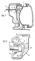
- FIG. 1 shows a headlight for motor vehicles
- FIG. 2 shows a first exemplary embodiment of the ball joint designed according to the invention
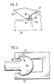
- FIG. 3 shows an enlarged partial view of the ball joint according to FIG. 2
- FIG. 4 shows a second exemplary embodiment of a ball joint.
- FIG. 1 A headlight for motor vehicles is shown in FIG. This consists of a reflector 1, which is rotatable in at least one fixed ball joint 4 and at least one further adjustable ball joint 3.
- the adjustable ball joint 3 is composed of a ball pin 2 and a ball pin bearing 9.
- the ball pin 2 consists of a threaded shaft 6 which is screwed through a threaded bushing 7 attached to the body of the motor vehicle and is connected at its end 5 to an adjusting device (not shown). At the other end of the shaft 6, a ball 10 is formed, which is mounted in the ball pin bearing 9.
- the ball pin bearing 9, as shown in Figure 2, is formed by a molded part 8 made of elastic plastic, which is designed so that it can be attached to the reflector 1 with simple means.
- the ball pin bearing 9 is composed of a dimensionally stable support bearing 11 and two diametrically opposite resilient arms 12.
- the support bearing 11 has two diametrically opposed bearing shells 15, which have approximately the shape of quarters of a hemisphere surface.
- the resilient arms 12 protrude from the molded part 8, only the end region of the arms 12 being elastically deformable, since the connection to the molded part 8 is reinforced by the stiffening ribs 13.
- the resilient arms 12 form an angle of 55 ° to the radial plane of the support bearing 11, can be deflected transversely to the radial plane and point with their ends to the support bearing 11.
- the surface 17 of the resilient arms 12 facing the ball 10 is adapted to the surface of the ball.
- the resilient arms 12, with their surface 17 facing the ball 10 partially enclose the ball 10 on the half of the ball opposite the support bearing 11 and hold the ball free of play in the support bearing.
- the ball 10 rests in the support bearing 11 on the bearing shells 15 and therefore cannot deflect in the radial plane of the support bearing when loaded.
- the angular mobility of the ball pin 2 is limited by the arms themselves, but in a plane perpendicular to this there is a large angular mobility of the ball pin 2.
- the ball 10 is placed on the resilient arms 12, which have a recess 14 along the direction of insertion of the ball for guiding and centering the ball 10.
- the resilient arms 12 are deflected in the direction of the support bearing 11 and the ball can slide between them into the support bearing.
- the ball 10 with its main diameter passes between the resilient arms 12, they rest on the half of the ball 10 opposite the support bearing and hold it in the support bearing 11.
- the ball pin 2 at the transition between the shaft 6 and ball 10 has an annular notch 18, forming an annular shoulder 19 inclined away from the ball to the axis 21 of the shaft, the angle between the annular shoulder 19 and the axis 21 is less than 90 °.
- the resilient arms 12 have a locking edge 23 protruding from the surface 17 and projecting into the notch, with an annular shoulder 20 pointing to the side of the support bearing 11. This locking edge 23 is arranged at a distance from the annular shoulder 19, so that the ball pin 2 pivots can execute by a certain angular amount until the annular shoulder 19 comes to rest against the annular shoulder 20.
- the angle formed by the annular shoulder 20 with the axis 21 viewed in the direction of the ball 10 is selected so that the annular shoulder 20 lies flat against the annular shoulder 19 when the ball is pivoted accordingly. This prevents the resilient arms 12 from sliding on the ball surface under very strong axial loads, since the ring shoulders interlock.
- the ball pin bearing 9 is formed only by the resilient arms 22.
- the support bearing 11 of Figure 2 or Figure 3 is omitted.
- the ball pin 2 is provided at the transition between the shaft 6 and the ball 10 with an annular notch 18 into which a surface of the resilient arms 22 facing the ball 10 protruding locking edge 23 engages, which is formed analogously to the above embodiment.
- the shaft of the ball pin 2 can also be guided through an axial opening in the support bearing 11.
- the notch 18 is arranged on the half of the ball 10 facing away from the support bearing 11 in the region of the resilient arms 12 engaging there, so that its detent edge 23 protrudes into the notch 18 to allow an angle of rotation play in the rotational position of the ball and press the ball pin 2 against being pushed out to back up.
Abstract
Description
Die Erfindung geht aus von einem Kugelgelenk nach der Gattung des Anspruchs 1 und 2. Es ist ein Kugelgelenk bekannt, bei dem über die federnden Arme aus elastischem Material ein Sicherungsring geschoben wird, so daß ein Auffedern der Arme und damit ein unbeabsichtigtes Heraussprengen des Kugelzapfens aus der Lagerung verhindert wird. Der zusätzlich erforderliche Sicherungsring und der dadurch erhöhte Montageaufwand sollten vermieden werden.The invention is based on a ball joint according to the preamble of
Mit dem erfindungsgemäßen Kugelgelenk mit den kennzeichnenden Merkmalen der Ansprüche 1 und 2 wird eine sichere Schnappverbindung erreicht, die kein zusätzliches Sicherungselement benötigt und die leicht montierbar ist.With the ball joint according to the invention with the characterizing features of
Durch die Weiterbildung des Kugelgelenks nach Anspruch 3 wird eine weitere Erhöhung der zum Ausknüpfen des Kugelzapfens erforderlichen Kraft erreicht.By further developing the ball joint according to
Durch die Weiterbildung des Kugelgelenks nach Anspruch 4 wird erreicht, daß nur eine geringe Montagekraft erforderlich ist, bei gleichzeitig hoher Ausknüpfkraft des Kugelzapfens.The development of the ball joint according to claim 4 ensures that only a small assembly force is required, with a high release force of the ball pin.
Zwei Ausführungsbeispiele der Erfindung sind in der Zeichnung anhand mehrerer Figuren dargestellt und in der nachfolgenden Beschreibung näher erläutert.Two exemplary embodiments of the invention are shown in the drawing with reference to several figures and are explained in more detail in the description below.
Es zeigen Figur 1 einen Scheinwerfer für Kraftfahrzeuge, Figur 2 ein erstes Ausführungsbeispiel des erfindungsgemäß ausgebildeten Kugelgelenks, Figur 3 eine vergrößerte Teilansicht des Kugelgelenks nach Figur 2 und Figur 4 ein zweites Ausführungsbeispiel eines Kugelgelenks.1 shows a headlight for motor vehicles, FIG. 2 shows a first exemplary embodiment of the ball joint designed according to the invention, FIG. 3 shows an enlarged partial view of the ball joint according to FIG. 2 and FIG. 4 shows a second exemplary embodiment of a ball joint.
In Figur 1 ist ein Scheinwerfer für Kraftfahrzeuge dargestellt. Dieser besteht aus einem Reflektor 1, der in wenigstens einem ortsfesten Kugelgelenk 4 drehbar und wenigstens einem weiteren verstellbaren Kugelgelenk 3 gelagert ist.A headlight for motor vehicles is shown in FIG. This consists of a reflector 1, which is rotatable in at least one fixed ball joint 4 and at least one further
Das verstellbare Kugelgelenk 3 setzt sich zusammen aus einem Kugelzapfen 2 und einer Kugelzapfenlagerung 9.The
Der Kugelzapfen 2 besteht aus einem Gewindeschaft 6, der durch eine an der Karrosserie des Kraftfahrzeuges angebrachte Gewindebuchse 7 geschraubt und an seinem Ende 5 mit einer nicht dargestellten Stellvorrichtung verbunden ist. An das andere Ende des Schafts 6 ist eine Kugel 10 angeformt, die in der Kugelzapfenlagerung 9 gelagert ist.The
Die Kugelzapfenlagerung 9 wird, wie in Figur 2 dargestellt, von einem Formteil 8 aus elastischem Kunststoff gebildet, das so gestaltet ist, daß es mit einfachen Mitteln am Reflektor 1 befestigt werden kann. Die Kugelzapfenlagerung 9 setzt sich zusammen aus einem formstabilen Stützlager 11 und zwei einander diametral gegenüberliegenden federnden Armen 12. Das Stützlager 11 weist zwei einander diametral gegenüberliegende Lagerschalen 15 auf, die etwa die Form von Viertelstücken einer Halbkugeloberfläche haben. Die federnden Arme 12 stehen vom Formteil 8 ab, wobei nur der Endbereich der Arme 12 elastisch verformbar ist, da die Verbindung zum Formteil 8 durch die Versteifungsrippen 13 verstärkt ist. Die federnden Arme 12 bilden zur Radialebene des Stützlagers 11 einen Winkel von 55°, sind quer zur Radialebene auslenkbar und weisen mit ihren Enden zum Stützlager 11 hin. Die der Kugel 10 zugewandte Oberfläche 17 der federnden Arme 12 ist der Kugeloberfläche angepaßt. Die federnden Arme 12 umschließen mit ihrer der Kugel 10 zugewandten Oberfläche 17 die Kugel 10 auf der dem Stützlager 11 gegenüberliegenden Hälfte der Kugel zum Teil und halten die Kugel spielfrei im Stützlager. Die Kugel 10 liegt im Stützlager 11 an den Lagerschalen 15 an und kann daher bei einer Belastung nicht in der Radialebene des Stützlagers ausweichen.The ball pin bearing 9, as shown in Figure 2, is formed by a molded
In der durch die beiden federnden Arme 12 gebildeten Ebene ist die Winkelbeweglichkeit des Kugelzapfens 2 durch die Arme selbst beschränkt, in einer Ebene senkrecht zu dieser ist jedoch eine große Winkelbeweglichkeit des Kugelzapfens 2 vorhanden.In the plane formed by the two
Zum Einführen des Kugelzapfens 2 in die Kugelzapfenlagerung 9 wird die Kugel 10 auf den federnden Armen 12 angelegt, die zur Führung und Zentrierung der Kugel 10 eine Vertiefung 14 längs der Einschubrichtung der Kugel aufweisen. Durch Drücken des Kugelzapfens 2 in Richtung des Stützlagers 11 werden die federnden Arme 12 ausgelenkt, und die Kugel kann zwischen diesen hindurch in das Stützlager gleiten. Wenn die Kugel 10 mit ihrem Hauptdurchmesser zwischen den federnden Armen 12 hindurch ist, legen sich diese an der dem Stützlager gegenüberliegenden Hälfte der Kugel 10 an und halten sie im Stützlager 11.To insert the
Ein Ausknüpfen des Kugelzapfens 2 aus der Kugelzapfenlagerung 9 wird durch die von den federnden Armen 12 in Richtung auf das Stützlager 11 mit ihrer Oberfläche 17 auf die Kugel 10 ausgeübten Kräfte erschwert.Uncoupling of the
In einer weiteren Ausgestaltung des Kugelgelenks 3, in Figur 3 dargestellt, weist der Kugelzapfen 2 am Übergang zwischen Schaft 6 und Kugel 10 eine ringförmige Einkerbung 18 auf, unter Bildung einer von der Kugel weg zur Achse 21 des Schafts geneigten Ringschulter 19, wobei der Winkel zwischen der Ringschulter 19 und der Achse 21 kleiner als 90° ist. Die federnden Arme 12 weisen eine aus der Oberfläche 17 hervorstehende, in die Einkerbung ragende Rastkante 23 auf mit einer zur Seite des Stützlagers 11 weisenden Ringschulter 20. Diese Rastkante 23 ist in einem Abstand von der Ringschulter 19 angeordnet, so daß der Kugelzapfen 2 eine Schwenkbewegung um einen bestimmten Winkelbetrag ausführen kann, bis die Ringschulter 19 an der Ringschulter 20 zur Anlage kommt. Der Winkel, den die Ringschulter 20 mit der Achse 21 in Richtung der Kugel 10 gesehen bildet, ist so gewählt, daß die Ringschulter 20 bei entsprechender Schwenklage der Kugel plan an der Ringschulter 19 anliegt. Dadurch wird ein Abgleiten der federnden Arme 12 auf der Kugeloberfläche unter sehr starker axialer Belastung verhindert, da sich die Ringschultern ineinander verhaken.In a further embodiment of the
In einem weiteren Ausführungsbeispiel, in Figur 4 dargestellt, wird die Kugelzapfenlagerung 9 nur von den federnden Armen 22 gebildet. Das Stützlager 11 von Figur 2 beziehungsweise Figur 3 entfällt. Um ein Herausgleiten der Kugel 10 aus den federnden Armen 22 unter axialer Belastung zu verhindern, ist der Kugelzapfen 2 am Übergang zwischen Schaft 6 und Kugel 10 mit einer ringförmigen Einkerbung 18 versehen, in die eine aus der der Kugel 10 zugewandten Oberfläche der federnden Arme 22 hervorstehende Rastkante 23 eingreift, die analog dem vorstehenden Ausführungsbeispiel ausgebildet ist.In a further embodiment, shown in Figure 4, the ball pin bearing 9 is formed only by the
In technisch äquivalenter Weise kann der Schaft des Kugelzapfens 2 auch durch eine axiale Öffnung im Stützlager 11 geführt sein.In a technically equivalent manner, the shaft of the
Auch bei dieser Ausführungsform wird die Einkerbung 18 auf der dem Stützlager 11 abgewandten Hälfte der Kugel 10 im Bereich der dort angreifenden federnden Arme 12 angeordnet, so daß deren Rastkante 23 ein Drehwinkelspiel bei der Kugeldrehstellung zulassend in die Einkerbung 18 ragen und den Kugelzapfen 2 gegen Herausdrücken sichern.In this embodiment, too, the
Claims (7)
Applications Claiming Priority (2)
| Application Number | Priority Date | Filing Date | Title |
|---|---|---|---|
| DE8811059U | 1988-09-01 | ||
| DE8811059U DE8811059U1 (en) | 1988-09-01 | 1988-09-01 |
Publications (3)
| Publication Number | Publication Date |
|---|---|
| EP0356750A2 true EP0356750A2 (en) | 1990-03-07 |
| EP0356750A3 EP0356750A3 (en) | 1991-06-12 |
| EP0356750B1 EP0356750B1 (en) | 1994-02-02 |
Family
ID=6827473
Family Applications (1)
| Application Number | Title | Priority Date | Filing Date |
|---|---|---|---|
| EP89114407A Expired - Lifetime EP0356750B1 (en) | 1988-09-01 | 1989-08-04 | Ball- and -socket joint, especially for adjusting devices for motor vehicle head-lights |
Country Status (3)
| Country | Link |
|---|---|
| US (1) | US5011322A (en) |
| EP (1) | EP0356750B1 (en) |
| DE (2) | DE8811059U1 (en) |
Cited By (6)
| Publication number | Priority date | Publication date | Assignee | Title |
|---|---|---|---|---|
| EP0572313A1 (en) | 1992-05-25 | 1993-12-01 | Valeo Vision | Ball fixation for the reflector of a vehicle headlamp |
| FR2713729A1 (en) * | 1993-12-07 | 1995-06-16 | Valeo Vision | Ball mounting for reflector in motor vehicle headlamp with adjusting rod |
| FR2733285A1 (en) * | 1995-04-19 | 1996-10-25 | Teledynamique Sa | Retaining coupling for linkage on motor vehicle gear box |
| DE102010023470A1 (en) * | 2010-06-11 | 2011-12-15 | Dr. Ing. H.C. F. Porsche Aktiengesellschaft | Support structure for pivot pin for motor vehicle, is guided in through hole by bushing, where passing guide is formed in axial guide section between bushing and pivot pin |
| DE102011003908A1 (en) * | 2011-02-10 | 2012-08-16 | Automotive Lighting Reutlingen Gmbh | Fixed bearing for light module for headlight of motor vehicle, has spherical or spherical-segment-shaped bearing element and counter bearing element accommodating partially to bearing element |
| EP2708763A2 (en) * | 2012-09-13 | 2014-03-19 | Zizala Lichtsysteme GmbH | Ball joint with movable locking means |
Families Citing this family (21)
| Publication number | Priority date | Publication date | Assignee | Title |
|---|---|---|---|---|
| US5492428A (en) * | 1991-11-08 | 1996-02-20 | Maclean-Fogg Company | Ball joint assembly |
| US6113301A (en) * | 1998-02-13 | 2000-09-05 | Burton; John E. | Disengageable pivot joint |
| US6247868B1 (en) | 1998-02-13 | 2001-06-19 | John E. Burton | Ball socket for pivot joint |
| EP0947718A3 (en) * | 1998-03-31 | 2000-04-19 | Honeywell Inc. | Shaft to actuator hub adapter |
| US6244735B1 (en) | 1999-05-11 | 2001-06-12 | John E. Burton | Headlamp adjuster with anti-rotation ball stud head |
| GB2351531A (en) * | 1999-06-26 | 2001-01-03 | Adwest Bowden Tsk Ltd | Ball socket assembly having an apertured ball retaining ring |
| US6758622B2 (en) | 2001-02-16 | 2004-07-06 | Burton Technologies Llc | Ball socket with improved pull-out force resistance |
| US6692176B1 (en) | 2002-04-02 | 2004-02-17 | Asyst Technologies Llc | Ball socket with locking feature |
| DE20208461U1 (en) * | 2002-05-31 | 2002-10-02 | Trw Automotive Safety Sys Gmbh | Assembly, in particular vehicle steering wheel trim |
| FR2845444B1 (en) * | 2002-10-04 | 2004-12-10 | Valeo Vision | ARTICULATION CAPSULE FOR A MOTOR VEHICLE LIGHTING PROJECTOR |
| FR2849123B1 (en) * | 2002-12-18 | 2006-01-06 | Peugeot Citroen Automobiles Sa | SELF-LOCKING CONNECTION BETWEEN A ROD END AND A FLAT PART |
| US20050061633A1 (en) * | 2003-08-25 | 2005-03-24 | Markus Bernhard Vetter | Retaining ring for sprockets |
| ITTO20040381A1 (en) * | 2004-06-08 | 2004-09-08 | Automotive Lighting Italia Spa | JOINT DEVICE OF A VEHICLE PROJECTOR |
| FR2878918B1 (en) * | 2004-12-07 | 2007-03-23 | Peugeot Citroen Automobiles Sa | AUTOBLOATING BONDING DEVICE BETWEEN A ROD CONTROL BODY AND A FLAT WORKPIECE AND A MOTOR VEHICLE EQUIPPED WITH AT LEAST ONE SUCH AUTOBLOATING BONDING DEVICE |
| US20070166096A1 (en) * | 2005-06-03 | 2007-07-19 | Lim Chong K | Joint assembly |
| US7459618B2 (en) * | 2006-01-12 | 2008-12-02 | Gibson Guitar Corp. | Locking tailpiece |
| DE102011003910B4 (en) * | 2011-02-10 | 2016-02-18 | Automotive Lighting Reutlingen Gmbh | Headlight of a motor vehicle |
| US9140294B2 (en) * | 2012-03-06 | 2015-09-22 | Burton Technologies, Llc | High extraction force ball socket |
| JP6054782B2 (en) * | 2013-03-19 | 2016-12-27 | スタンレー電気株式会社 | Pivot holder structure for vehicle lamp |
| US10155469B1 (en) | 2017-06-15 | 2018-12-18 | Valeo North America, Inc. | Adjustment assembly for vehicle lights having bracket connected to a support member via a plurality of connectors, each connector having a body and a connector head that articulates within a socket |
| US11585510B2 (en) | 2021-04-30 | 2023-02-21 | Valeo North America, Inc. | Light system including an adjustment assembly to aim a light |
Citations (6)
| Publication number | Priority date | Publication date | Assignee | Title |
|---|---|---|---|---|
| FR1053159A (en) * | 1952-03-28 | 1954-02-01 | Renault | Improvements to removable ball joints |
| FR2101999A7 (en) * | 1970-09-03 | 1972-03-31 | Bosch | |
| US4004771A (en) * | 1972-09-09 | 1977-01-25 | Gewerkschaft Eisenhutte Westfalia | Ball-and-socket type connections for use with mining apparatus |
| US4118131A (en) * | 1975-04-12 | 1978-10-03 | Stabilus Gmbh | Pneumatic spring |
| DE2631926B2 (en) * | 1975-07-15 | 1979-05-10 | Cibie Projecteurs S.A., Bobigny (Frankreich) | Optical block for a motor vehicle headlight |
| FR2574032A1 (en) * | 1984-12-05 | 1986-06-06 | Cibie Projecteurs | Device for adjusting the orientation of a motor vehicle headlight |
Family Cites Families (5)
| Publication number | Priority date | Publication date | Assignee | Title |
|---|---|---|---|---|
| US3856422A (en) * | 1973-05-29 | 1974-12-24 | W Trefry | Retention clip for ball and socket joint |
| DE2512253C3 (en) * | 1975-03-20 | 1978-10-19 | Itw-Ateco Gmbh, 2000 Norderstedt | Joint socket for an angle joint |
| FR2345614A2 (en) * | 1976-03-25 | 1977-10-21 | Itw De France | KNEE JOINT BOWL |
| US4499785A (en) * | 1982-06-28 | 1985-02-19 | Teleflex Incorporated | Molded ball socket terminal (connecting belts) |
| US4694705A (en) * | 1982-06-28 | 1987-09-22 | Teleflex Incorporated | Molded terminal for remote control assembly (lollipop) |
-
1988
- 1988-09-01 DE DE8811059U patent/DE8811059U1/de not_active Expired - Lifetime
-
1989
- 1989-07-13 US US07/379,805 patent/US5011322A/en not_active Expired - Fee Related
- 1989-08-04 EP EP89114407A patent/EP0356750B1/en not_active Expired - Lifetime
- 1989-08-04 DE DE89114407T patent/DE58906874D1/en not_active Expired - Fee Related
Patent Citations (6)
| Publication number | Priority date | Publication date | Assignee | Title |
|---|---|---|---|---|
| FR1053159A (en) * | 1952-03-28 | 1954-02-01 | Renault | Improvements to removable ball joints |
| FR2101999A7 (en) * | 1970-09-03 | 1972-03-31 | Bosch | |
| US4004771A (en) * | 1972-09-09 | 1977-01-25 | Gewerkschaft Eisenhutte Westfalia | Ball-and-socket type connections for use with mining apparatus |
| US4118131A (en) * | 1975-04-12 | 1978-10-03 | Stabilus Gmbh | Pneumatic spring |
| DE2631926B2 (en) * | 1975-07-15 | 1979-05-10 | Cibie Projecteurs S.A., Bobigny (Frankreich) | Optical block for a motor vehicle headlight |
| FR2574032A1 (en) * | 1984-12-05 | 1986-06-06 | Cibie Projecteurs | Device for adjusting the orientation of a motor vehicle headlight |
Cited By (10)
| Publication number | Priority date | Publication date | Assignee | Title |
|---|---|---|---|---|
| EP0572313A1 (en) | 1992-05-25 | 1993-12-01 | Valeo Vision | Ball fixation for the reflector of a vehicle headlamp |
| US5443323A (en) * | 1992-05-25 | 1995-08-22 | Valeo Vision | Mounting device for a mobile part of a headlamp |
| FR2713729A1 (en) * | 1993-12-07 | 1995-06-16 | Valeo Vision | Ball mounting for reflector in motor vehicle headlamp with adjusting rod |
| ES2113282A1 (en) * | 1993-12-07 | 1998-04-16 | Valeo Vision | Ball mounting for reflector in motor vehicle headlamp with adjusting rod |
| FR2733285A1 (en) * | 1995-04-19 | 1996-10-25 | Teledynamique Sa | Retaining coupling for linkage on motor vehicle gear box |
| DE102010023470A1 (en) * | 2010-06-11 | 2011-12-15 | Dr. Ing. H.C. F. Porsche Aktiengesellschaft | Support structure for pivot pin for motor vehicle, is guided in through hole by bushing, where passing guide is formed in axial guide section between bushing and pivot pin |
| DE102011003908A1 (en) * | 2011-02-10 | 2012-08-16 | Automotive Lighting Reutlingen Gmbh | Fixed bearing for light module for headlight of motor vehicle, has spherical or spherical-segment-shaped bearing element and counter bearing element accommodating partially to bearing element |
| DE102011003908B4 (en) * | 2011-02-10 | 2019-04-18 | Automotive Lighting Reutlingen Gmbh | Headlight of a motor vehicle |
| EP2708763A2 (en) * | 2012-09-13 | 2014-03-19 | Zizala Lichtsysteme GmbH | Ball joint with movable locking means |
| EP2708763A3 (en) * | 2012-09-13 | 2014-06-18 | Zizala Lichtsysteme GmbH | Ball joint with movable locking means |
Also Published As
| Publication number | Publication date |
|---|---|
| US5011322A (en) | 1991-04-30 |
| EP0356750A3 (en) | 1991-06-12 |
| EP0356750B1 (en) | 1994-02-02 |
| DE8811059U1 (en) | 1989-12-28 |
| DE58906874D1 (en) | 1994-03-17 |
Similar Documents
| Publication | Publication Date | Title |
|---|---|---|
| EP0356750B1 (en) | Ball- and -socket joint, especially for adjusting devices for motor vehicle head-lights | |
| DD252657A5 (en) | VEHICLE HEADLIGHTS | |
| DE4028931A1 (en) | ROTARY ENCODER | |
| WO1993022574A1 (en) | Rolled bearing bush and journal or shaft connection with such a bearing bush | |
| DE102017130605A1 (en) | Tolerance compensation arrangement with clamp protection | |
| EP1559605B1 (en) | Securing means for a container cap | |
| DE4112132B4 (en) | leverage | |
| DE3509831C2 (en) | Reflector mounting for motor vehicle headlights | |
| DE112007000611B4 (en) | Electrical connector and electrical connector with different engagement and operative retention forces | |
| DE3218325A1 (en) | CLUTCH RELEASE, ESPECIALLY FOR MOTOR VEHICLES | |
| DE2201874A1 (en) | BEARING BUSH | |
| DE3210954A1 (en) | BALL JOINT | |
| DE2624144A1 (en) | ACTUATOR FOR AN ELECTRIC SWITCH | |
| DE19912685A1 (en) | Drive device to adjust mirror glass carrier located in pivoted fashion in mirror housing of car's rear view mirror | |
| WO2018153929A1 (en) | Fastening device and fastening subassembly | |
| DE102017130998A1 (en) | Mounting arrangement with angle compensation function | |
| DE2831204C2 (en) | Miniature step switch | |
| EP0794087B1 (en) | Extension rearview miror for vehicles, especially for motor vehicles | |
| DE202019104173U1 (en) | Device for fastening a first component to a second component | |
| DE4204630C2 (en) | Ball catch for fixing the position of a movable control element | |
| DE4010137A1 (en) | DEVICE FOR STORING A MANUAL TRANSMISSION LEVER | |
| DE3229984A1 (en) | Rope-pulley arrangement | |
| EP0612925A1 (en) | Pivot joint | |
| DE2341200B2 (en) | Ball joint | |
| DE2620076B2 (en) | Caster |
Legal Events
| Date | Code | Title | Description |
|---|---|---|---|
| PUAI | Public reference made under article 153(3) epc to a published international application that has entered the european phase |
Free format text: ORIGINAL CODE: 0009012 |
|
| AK | Designated contracting states |
Kind code of ref document: A2 Designated state(s): DE FR GB IT |
|
| PUAL | Search report despatched |
Free format text: ORIGINAL CODE: 0009013 |
|
| RHK1 | Main classification (correction) |
Ipc: F16C 11/06 |
|
| AK | Designated contracting states |
Kind code of ref document: A3 Designated state(s): DE FR GB IT |
|
| 17P | Request for examination filed |
Effective date: 19911112 |
|
| RAP3 | Party data changed (applicant data changed or rights of an application transferred) |
Owner name: ROBERT BOSCH GMBH |
|
| 17Q | First examination report despatched |
Effective date: 19921125 |
|
| GRAA | (expected) grant |
Free format text: ORIGINAL CODE: 0009210 |
|
| AK | Designated contracting states |
Kind code of ref document: B1 Designated state(s): DE FR GB IT |
|
| GBT | Gb: translation of ep patent filed (gb section 77(6)(a)/1977) |
Effective date: 19940216 |
|
| REF | Corresponds to: |
Ref document number: 58906874 Country of ref document: DE Date of ref document: 19940317 |
|
| ET | Fr: translation filed | ||
| ITF | It: translation for a ep patent filed |
Owner name: STUDIO JAUMANN |
|
| PLBE | No opposition filed within time limit |
Free format text: ORIGINAL CODE: 0009261 |
|
| STAA | Information on the status of an ep patent application or granted ep patent |
Free format text: STATUS: NO OPPOSITION FILED WITHIN TIME LIMIT |
|
| 26N | No opposition filed | ||
| REG | Reference to a national code |
Ref country code: FR Ref legal event code: D6 |
|
| REG | Reference to a national code |
Ref country code: GB Ref legal event code: 746 Effective date: 19951207 |
|
| ITPR | It: changes in ownership of a european patent |
Owner name: OFF.TA LIC.ZA AL PUBBLICO OFF.TA DI LICENZA |
|
| PGFP | Annual fee paid to national office [announced via postgrant information from national office to epo] |
Ref country code: GB Payment date: 19990726 Year of fee payment: 11 |
|
| PGFP | Annual fee paid to national office [announced via postgrant information from national office to epo] |
Ref country code: FR Payment date: 19990813 Year of fee payment: 11 |
|
| PGFP | Annual fee paid to national office [announced via postgrant information from national office to epo] |
Ref country code: DE Payment date: 19991026 Year of fee payment: 11 |
|
| PG25 | Lapsed in a contracting state [announced via postgrant information from national office to epo] |
Ref country code: GB Free format text: LAPSE BECAUSE OF NON-PAYMENT OF DUE FEES Effective date: 20000804 |
|
| GBPC | Gb: european patent ceased through non-payment of renewal fee |
Effective date: 20000804 |
|
| PG25 | Lapsed in a contracting state [announced via postgrant information from national office to epo] |
Ref country code: FR Free format text: LAPSE BECAUSE OF NON-PAYMENT OF DUE FEES Effective date: 20010430 |
|
| PG25 | Lapsed in a contracting state [announced via postgrant information from national office to epo] |
Ref country code: DE Free format text: LAPSE BECAUSE OF NON-PAYMENT OF DUE FEES Effective date: 20010501 |
|
| REG | Reference to a national code |
Ref country code: FR Ref legal event code: ST |
|
| PG25 | Lapsed in a contracting state [announced via postgrant information from national office to epo] |
Ref country code: IT Free format text: LAPSE BECAUSE OF NON-PAYMENT OF DUE FEES Effective date: 20050804 |