EP0355897A2 - Châssis pour un élément de direction, en particulier pour un patin à roulettes - Google Patents
Châssis pour un élément de direction, en particulier pour un patin à roulettes Download PDFInfo
- Publication number
- EP0355897A2 EP0355897A2 EP89202035A EP89202035A EP0355897A2 EP 0355897 A2 EP0355897 A2 EP 0355897A2 EP 89202035 A EP89202035 A EP 89202035A EP 89202035 A EP89202035 A EP 89202035A EP 0355897 A2 EP0355897 A2 EP 0355897A2
- Authority
- EP
- European Patent Office
- Prior art keywords
- chassis
- axle
- accordance
- link
- steerable element
- Prior art date
- Legal status (The legal status is an assumption and is not a legal conclusion. Google has not performed a legal analysis and makes no representation as to the accuracy of the status listed.)
- Granted
Links
Images


Classifications
-
- A—HUMAN NECESSITIES
- A63—SPORTS; GAMES; AMUSEMENTS
- A63C—SKATES; SKIS; ROLLER SKATES; DESIGN OR LAYOUT OF COURTS, RINKS OR THE LIKE
- A63C17/00—Roller skates; Skate-boards
- A63C17/04—Roller skates; Skate-boards with wheels arranged otherwise than in two pairs
- A63C17/06—Roller skates; Skate-boards with wheels arranged otherwise than in two pairs single-track type
- A63C17/08—Roller skates; Skate-boards with wheels arranged otherwise than in two pairs single-track type single-wheel type with single axis
-
- A—HUMAN NECESSITIES
- A63—SPORTS; GAMES; AMUSEMENTS
- A63C—SKATES; SKIS; ROLLER SKATES; DESIGN OR LAYOUT OF COURTS, RINKS OR THE LIKE
- A63C17/00—Roller skates; Skate-boards
- A63C17/01—Skateboards
-
- A—HUMAN NECESSITIES
- A63—SPORTS; GAMES; AMUSEMENTS
- A63C—SKATES; SKIS; ROLLER SKATES; DESIGN OR LAYOUT OF COURTS, RINKS OR THE LIKE
- A63C17/00—Roller skates; Skate-boards
- A63C17/01—Skateboards
- A63C17/011—Skateboards with steering mechanisms
- A63C17/012—Skateboards with steering mechanisms with a truck, i.e. with steering mechanism comprising an inclined geometrical axis to convert lateral tilting of the board in steering of the wheel axis
-
- A—HUMAN NECESSITIES
- A63—SPORTS; GAMES; AMUSEMENTS
- A63C—SKATES; SKIS; ROLLER SKATES; DESIGN OR LAYOUT OF COURTS, RINKS OR THE LIKE
- A63C17/00—Roller skates; Skate-boards
- A63C17/04—Roller skates; Skate-boards with wheels arranged otherwise than in two pairs
- A63C17/06—Roller skates; Skate-boards with wheels arranged otherwise than in two pairs single-track type
- A63C17/061—Roller skates; Skate-boards with wheels arranged otherwise than in two pairs single-track type with relative movement of sub-parts on the chassis
- A63C17/064—Roller skates; Skate-boards with wheels arranged otherwise than in two pairs single-track type with relative movement of sub-parts on the chassis comprising steered wheels, i.e. wheels supported on a vertical axis
-
- A—HUMAN NECESSITIES
- A63—SPORTS; GAMES; AMUSEMENTS
- A63C—SKATES; SKIS; ROLLER SKATES; DESIGN OR LAYOUT OF COURTS, RINKS OR THE LIKE
- A63C17/00—Roller skates; Skate-boards
- A63C17/22—Wheels for roller skates
- A63C17/223—Wheel hubs
Definitions
- a chassis arrangement having a steerable element which is steerable on tilting of the chassis relative to the ground is known from international application No. WO 88/04565.
- the steerable element is mounted on the chassis via first and second links.
- the first link is pivotally supported at one end on said chassis and supports a substantially horizontally disposed axle for said steerable element
- the second link is pivotable about an axis disposed parallel or oblique to the ground and substantially intersecting the contact area, where, in the straight ahead position of the steerable element, the latter contacts the ground.
- first and second links defining a substantially vertical axis which substantially intersects the first said axis at said contact area, and the steerable element is swivellable about this vertical axis to effect steering on pivotal movement of said second link about the first said axis under the moment created by the ground pressure and its moment arm about the first said axis resulting from tilting of the chassis.
- the known chassis (international application publication No. WO 88/04565) is particularly envisaged for use with a roller skate, a skateboard, a roller ski, a roller bob, a snow scooter or the like, i.e. with devices where steering is produced as a result of displacement of the user's weight resulting in tilting of the chassis.
- the steering element can have different forms, for example a wheel in a roller skate or skateboard, a caterpillar type device in a dry ski, or a ski, slid or mow device in a snow scooter, this term will be understood whereever it is used in the specification, to cover any of the relevant items, depending on the particular construction of the device involved.
- the kinematics of a chassis of the above described kind are such that frictional forces acting sideways on the steerable element or wheel have substantially no effect on the steering, since they have no moment arm about either of the relevant axes, i.e. the first said axis or the vertical axis.
- the reaction force at the contact patch also has substantially no moment arm about either of the said axes, since it acts substantially vertically through the vertical steering axis.
- the reaction force also has no relevant moment arm which could induce a steering moment. If, on the other hand, the user displaces his weight so that the chassis is tilted relative to the ground, the reaction force of the ground is moved sideways so that it now has a moment arm about the first said axis.
- a yet further object of the present invention is to provide a wheel and axle assembly which could be mounted on a supermarket trolley to make the same more easily steerable.
- the present invention is characterised in that said means provided between said first and second links defining said substantially vertical axis is disposed in the center region of said steerable element, in the region of said horizontally disposed axle.
- the means does not take up any space about the steerable element and the chassis can be lowered until it is only just clear of the steerable element.
- a particularly preferred embodiment is characterised in that said means defining a substantially vertical axis comprises an axle tube supported by said first link with said steerable element being mounted on said axle tube; an axle shaft supported by said second link and extending with clearance through said axle tube; and pin means defining said substantially vertical axis and extending between said axle tube and said axle shaft.
- the pin means defining the substantially vertical axis is wholly disposed within the center of the wheel, or between a pair of wheels if two wheels are mounted on said axle tube. This is a protected position where the pin means can readily be protected against the ingress of abrasive elements or water of the like, which would otherwise result in deterioration of the chassis.
- the pin means preferably comprises two pointed gimbal pins engaging in respective conical recesses in the surface of said axle shaft.
- the pins are characterised in that said gimbal pins are threaded at the outside and engage in screw threads in said axle tube.
- axle shaft can be made thickest at the portion where the pins engage, thus ensuring that the axle shaft is strong at the position of maximum bending moment.
- axle shaft can be made more slender towards its ends, thus providing an ample clearance between the axle tube and the axle rod to permit steering of the wheel.
- the axle tube itself can be thickened in the region where the pins engage to provide shoulders adjacent the thickened region against which the bearings for the wheel can be mounted.
- the thickened portion serves two purposes, namely to support the bearings in the axial direction of the axle tube and to provide a support for the threaded pins.
- first and second links can readily be formed as forks as set forth in claim 6 and can be secured to the chassis in preferred manner described in claims 7 to 10.
- first and second links take the form of single arms which are preferably constructed and arranged in the manner defined in claims 12, 13 and 14.
- the pin and the vertical axis defined thereby will normally be disposed in a vertical plane perpendicular to the straightahead direction of the steerable element but inclined in that plane towards the ground contact area or patch.
- the pin itself may be an integral part of an axle for the steerable element (wheel) or it may be a separate pin. In a particularly preferred arrangement the pin is supported at two spaced apart locations on said axle and at two spaced apart locations on said second link.
- chassis arrangement of the present invention has the advantage that it is entirely reversible so that only one chassis arrangement needs to be manufactured and can be used as desired for the front or rear wheel.
- a steerable element of this kind is not only suitable as a spare part for the chassis arrangement already described it can also be substituted for the steered wheels in the two-wheeled roller skate of Swiss patent 603 198, in the chassis ot the abovementioned international application WO 88/04565 and in the chassis of the further international application No. WO 88/04564.
- resilient means is preferably provided between the axle tube and the axle shaft to provide a restoring moment to the normal straightahead steering position.
- resilient means could for example comprise an elastomeric compound injected into the clearances between the axle tube and the axle shaft or it could comprise metallic spring elements disposed between the axle tube and the axle shaft.
- the axis directed towards the region of contact between the steerable element and the ground will normally be a vertical axis.
- the axis is an inclined axis.
- the inclined axis will be disposed in a vertical plane containing the normal straightahead direction of said steerable element but will be inclined so that it points forwardly and downwardly through the contact region.
- a steerable element of this kind has the particularly surprising advantage that it can be substituted for the normal wheels of an in-line skate to produce an improved skate capable of permitting the user to skate in circular arcs. It is possible for the axle shaft to be mounted rigidly in the chassis, steering resulting solely from the freedom of movement provided for the steerable element by the disposition of the inclined axis. In general the steerable element will be a wheel mounted via bearings on the axle tube.
- axle shaft could for example be mounted in a fork which is pivotally mounted on the chassis about a horizontal axis (in the normal straightahead position), e.g. in the manner of a leading or trailing fork suspension for a motor cycle.
- springing is possible to improve ground contact and ride comfort. Such springs will then act between the fixed part of the chassis and the leading or trailing fork supporting the axle shaft of the steerable element.
- the use of a forked element to hold the axle shaft is preferred it is also quite possible to support the axle shaft at only one end by means of a suitably dimensioned leading or trailing link.
- the steerable element may also be fixed rigidly to the chassis via a single post connecting one end of the axle shaft to the chassis.
- This arrangement improves the straight line stability of the steerable element, and of a chassis on which it is mounted and also compensates for wear of the steerable element.
- This wear compensation aspect can be important if the steerable element is a wheel provided with a solid tyre in the manner of a roller skate, since such solid tyres are subjected to considerable wear in use resulting in a substantial change in diameter of the steerable element. in some circumstances advantages can be gained by displacing the notional point of intersection of the inclined axis with said contact region behind the centre of said contact region.
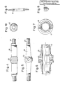
- a chassis 10 for a roller skate having two single wheels 11 and 12 at its front and rear ends respectively.
- the chassis arrangement 13 for the wheel 11 is identical to the chassis arrangement 14 for the wheel 12, the two chassis arrangements are merely reversed in the way that they are attached to the basic chassis 10.
- the basic chassis 10 in the drawing is a single piece it could however also be two pieces which are movable relative to one another in the longitudinal direction of the roller skate to facilitate adaptation to difference shoe sizes.
- Buffers 15 and 16 are provided at the extreme front and rear ends of the roller skate.
- a pin 31 extends in a vertical direction through the axle tube and the axle shaft and thus defines a vertical axis 35 about which the wheel can rotate for steering movements.
- the spigot 27 defines an axis 36 which, when projected, passes through the ground contact patch 37 between the wheel 12 and the ground 38. Since the spherical head 20 is rotatable in all directions about its center the first link 17 is also rotatable about an axis 39 which when projected also extends through the contact patch 37 and intersects with the vertical axis 35 and the first said axis 36.
- the axle tube is thickened between the two bearings 22, 23 to provide an abutment shoulder for the inner races of these bearings.
- the fork ends 19 of the first link 17 engage on annular shoulders of the axle tube, and these end shoulders are turned over, i.e. permanently deformed at 41 to permanently retain the ends of the first links on the axle tube.
- a circlip to retain the fork ends 19 on the axle tube.
- the fork ends of the second links are retained on the axle shaft by means of a nut and washer assembly 42, 43, with the nut 42 being screwed onto a screw thread 44 at the end of the axle tube.
- the washer 43 is secured against rotation by means of a flat on the end of the axle shaft and a correspondingly shaped recess in the washer.
- the rubber bushes 33, 34 provide a restoring force, i.e. a restoring moment about the axis 36, which tends to restore the wheels to the straight position.
- shields 57 are disposed between the fork ends of the first links 17 and the associated inner races of the bearings 22, 23 and serve to protect the bearings against the ingress of contamination.
- the ends of the axle tube are turned over the fork ends of the first link to secure them at 41.
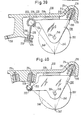
- the mounting of the fork ends of the second link 18 is effected in the same manner in the embodiment of Fig. 3 as in Fig. 2.
- the individual parts, namely the axle tube 21, the axle rod 26, the gimbal pins 51, the bearing shield 57, the securing nut 42, and the locking washer 43 which fits on a flat at the end of the axle rod 26 can be seen in the scale 2 to 1 in Figs. 4 to 10 of the drawings.
- Figs. 11 and 12 there are shown modified versions of the axle shaft and axle tube previously described, for example with reference to Figs. 5 and 6. Parts in Figs. 11 and 12 and in the later figures having counter-parts in the earlier figures will be designated with the same reference numerals.
- the broken line 67 indicates that the axis can also be positioned so that it does not pass through the centre 68 of the ground contact patch, as does the axis 66, but instead intersects the ground at a point 68′ located at a distance d in front of the centre of the ground contact patch 68.
- This arrangement tends to improve the self-centering of the wheel and also compensates for wear in the solid tyre which leads conceptually to vertically upward movement of the centre 68 of the ground contact patch.
- the broken line 69 shows that the axis can also be placed so that it intersects the ground behind the centre 68 of the ground contact patch.
- Fig. 15 shows an embodiment in which the axle shaft is supported at one end only.
- the axle shaft 26 is formed integrally with the second link 18 and the axle tube 21 is formed integrally with the first link 17 as can be seen more clearly from the plan view of Fig. 16.
- the vertical axis 35 is realised in a slightly different manner.
- the end of the axle shaft 26 remote from the second link 18 is namely provided with a spigot 71 which engages in a cylindrical bearing sleeve 72 mounted in the axle shaft 21, with the central longitudinal axis of the cylindrical bearing sleeve 72 being coincident with the vertical axis 35.
- a single gimbal pin 51 which is again radially directed through the tubular portion of the axle sleeve 21 into an appropriately shaped recess 73 in the end of the axle shaft 26 remote from the link 18.
- the recess 73 is in this embodiment a cylindrical recess and contains a cup-shaped liner 74, the cylindrical walls of which are disposed coaxial to the vertical axis 35 and the bottom portion of which forms an abutment for the gimbal pin 51.
- the gimbal pin 51 is adjusted so that there is essentially no free play in the vertical direction between the end of the axle shaft 26 and the wheel. Thrust loads are transmitted to the axle shaft 26 from the wheel via the horizontal flange 75 of the cylindrical liner 72.
- a lock nut 76 is provided to secure the gimbal pin 51 in position.
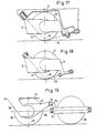
- Figs. 17, 18 and 19 show how a steerable element in the form of a wheel and having a vertical steering axis 35 (for example in accordance with the embodiment of Figs. 2 to 10) can be incorporated into various chassis designs.
- Fig. 17 shows an embodiment which is in fact closely similar to Fig. 1 of the present drawings but in which the rubber bushes 33, 34 are no longer used since these bushes are now incorporated as a resilient elastomeric composition in the hollow axle tube surrounding the axle shaft 26.
- the basic geometry of Fig. 1 is retained with the three intersecting axes 39, 35 and 37.
- Fig. 19 shows an embodiment which resembles the chassis shown in international application, publication No. WO 88/04564 in which tilting of the chassis, as sensed by laterally disposed wheels 80 (only one of which is shown in Fig. 17), produces turning of a horizontally mounted axle 81 in the clockwise or anti-clockwise direction (X). This in turn produces steering movement of a front wheel 82.
- the axle tube is connected to a first link 83 which cooperates at its rear end with a ball-shaped member 85 at the end of a radial arm 84 of the shaft 81.
- the axle shaft is fixedly connected via a pair of forks 86 to the base member 87 of the chassis.
- steerable element is preferably a wheel it could also be used with other forms of steerable element.
- Figs. 13 and 14 show two further possible embodiments. Since the geometry of these embodiments is basically similar to that of Fig. 1 the same reference numerals have been used to designate the individual parts and the description of parts common to the embodiment of Fig. 1 will not be given.
- the wheel 11 of the Fig. 13 embodiment is supported by links provided only at one side of the chassis 10.
- the first link is integral with a bar or tube 21 forming an axle for the wheel 11 and it will be understood that the wheel 11 is supported on the axle 21 via one or more bearings.
- the pin 90 is slidingly rotatably received in a cylindrical bearing 93 formed in the wheel end of the second link 18.
- the means provided between the first and second links defining said substantially vertical axis is disposed in the centre region of the steerable element, in the region of the horizontally disposed axle 21.
- Fig. 14 shows a slightly refined embodiment of the steerable wheel of the embodiment of Fig. 13.
- the pin 90 is a threaded pin which is screwed into a lug 94 provided on the axle 21 adjacent the point at which it merges into the first link 17.
- the pin also passes through a further lug 95 of the axle tube and is thus supported at two spaced apart locations in the axle tube 21.
- the end of the first link 18 is also provided with two spaced apart lugs 96 and 97 through which the pin 90 passes. Since the pin is doubly supported it can be made relatively slender without being liable to breakage.
- the embodiment of Fig. 14 enables a particularly compact arrangement to be realised.
- the inclined axis 92 intersects the notional vertical axis 35 at the centre of the ground contact patch at 68.
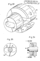
- Fig. 20 there is shown an alternative embodiment of the axle tube 21 in accordance with the present invention.
- This axle tube, or rather the complete axle assembly is also suitable for mounting in a chassis by an arrangement in which the ends of the axle shaft are supported directly by the chassis or indirectly via a single pivoted fork, e.g. in the form of a pair of trailing or leading arms.
- the axle shaft could be mounted on a chassis by a single link which is connected to one end of the axle shaft only and which could be mounted about a horizontal pivot axis at its other end, e.g. by a torsion bar, e.g. as a front and/or rear wheel of a motorbike.
- no further link means are used to connect the ends of the axle tube to the chassis. This is also fundamentally possible with the embodiments described earlier, particularly if the vertical axis is tilted in the vertical longitudinal plane of the chassis.
- the axle tube 21 has a centrally disposed support portion 100 which in this embodiment is integrally formed with the material of the axle tube 21.
- the support portion 100 comprises two arms 101, 102 which project in a generally radial plane away from the axis of the axle tube 21.
- a space 103 is defined between the two arms 101, 102 and communicates via an opening 104 with the interior 105 of the axle tube.
- Formed in the arms 101, 102 at the ends thereof are threaded bores 106, 107 which accommodate gimbal pins for supporting the axle shaft in a manner which will later be described.
- the support portion 100 has two radially directed cylindrical recesses 108, 109, that is to say recesses which are aligned on an axis radial to the central longitudinal axis of the axle tube 21 which serve to accommodate resilient spring elements in a manner which will be described later. It suffices to state here, that the recesses 108, 109 are threaded at their end portions, for example as shown at 111 in Fig. 20 to receive caps.
- Figs. 20 The precise shape of the axle tube of Fig. 20 can also be seen with reference to the partly sectioned illustrations of Figs. 21 and 22.
- Figs. 20, 21 and 22 show the axis formed by the gimbal pins as being substantially vertically directed, it will be understood that in the inbuilt position of the axle this axis subtends the angle ⁇ described previously in relation to Fig. 12.
- Fig. 23 there can be seen a side view of the axle shaft used with the axle tube of Figs. 20 to 22.
- the axle shaft 26 of Fig. 23 is in fact pressed into a bore 112 of a yoke member 113 and indeed until the collar 114 on the shaft 26 abuts against the shoulder 115 of the yoke 113.
- the bore 112 and the corresponding mating portion 116 of the axle 26 are preferably tapered fractionally, so that the conical surfaces ensure easy introduction of the axle shaft into the yoke and a tight fit.
- the yoke 113 has a nose portion 116 which projects through the opening 104 of the axle tube 21 of Figs.
- the nose 116 has two conical recesses 117, 118 which receive the points of the gimbal pins inserted through the bores 106, 107 of the embodiment of Fig. 20.
- the yoke 113 must be inserted into the axle tube and between the arms 101 and 102 before the shaft 26 is pressed through the bore 112.
- the ends of the shaft 26 are formed in the same way as the ends of the shaft of Figs. 4 and 5 and will not be described here in further detail.
- the shaft is provided with a transverse bore 119 with a corresponding transverse bore 120 being formed in the yoke 113.
- the purpose of these transverse bores 119 and 120 is to accept a shouldered pin 121 as shown in Fig. 26.
- the shouldered pin has a portion 122 which extends through the two bores 119 and 120, a shoulder or collar 123 which prevents the pin falling through two bores 120 and 119, i.e. provides a positive step limiting the movement of the shoulder pin, and two spigots 124 and 125 which after insertion of the pin project into the cylindrical recesses 108 and 109 of the axle tube.
- the portion 122 can be tapered.
- shouldered pin is also inserted through the yoke 113 and the axle shaft 26 after the latter two components have been united in the axle tube.
- the shouldered pin has a double function in as much as it not only transmits the resetting force to the axle shaft but also secures the axle shaft within the yoke 113.
- first and second bearings typically ball bearings are pushed over the cylindrical shoulders of the axle tube on either side of the support portion 100. I.e. until the inner races of the bearings abut against the ring shoulders formed on and directly adjacent the support portion 100.
- means may be provided at the ends of the axle tube for securing the bearing inner races.
- axle tube and the yoke have been made of an aluminium alloy and the shaft of the steel alloy.
- the gimbal pins which in the embodiment under discussion have conical points (although they could also have other shaped ends, for example hemispherical ends) the gimbal pins are not threaded directly into the aluminium alloy but rather into cylindrical steel inserts pressed into the aluminium alloy.
- these inserts are shouldered cylindrical inserts or conical inserts which are pressed into the arms 101 and 102 from within the space 103, so that their shape prevents them from being pushed outwardly by the forces acting on the gimbal pin.
- Figs. 29 to 30 is preferably formed as an injection molding in a fibre reinforced plastic and has the special feature that the arms 101 and 102 are connected together by a bridge piece 130 which merges via a web 131 into the yoke 113 surrounding the axle shaft 26.
- the axle shaft is formed in this case of steel and is embedded in the yoke 113 during the injection molding thereof.
- the web 131 has a narrowed portion at 132 which defines the axis 64 which permits limited relative pivotal deflection or steering movement between the axle shaft and the axle tube. In the embodiment shown this narrowed portion 132 extends over the full vertical depth of the web 131.
- this embodiment is preferred for a synthetic axle tube, it could also be realised in metal. It need not necessarily be made in one piece but could be assembled, for example the bridge piece 130 could be made in one piece with the yoke 131 and screwed to the ends of the arms 101, 102.
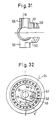
- axle assembly Another possibility for forming the axle assembly would be to make the axle tube of C-shaped section, i.e. with a continuous slot along its length as shown in Fig. 31.
- the C-section resembles the axle tube of the Figs. 20 to 23, however the C-shaped cross-section of the axle tube is not restricted to this embodiment, it could also be used for example with the embodiment of Figs. 29 to 30, and indeed irrespective of whether the axle tube is made there of one piece with a composite assembly.
- the tube could be resiliently dilated to allow gimbals to be inserted between the yoke 113 and the arms 101, 102, e.g. gimbals in the form of ball bearings, thus simplifying the design.
- the gimbals could be an integral part of the yoke, or at least previously assembled therein.
- Fig. 32 shows another particularly important embodiment.
- the axle tube assembly is formed by the inner race of the bearing and this inner race is provided with noses 140, 141 which are spaced apart to receive the nose of a yoke 113 fashioned similarly to the yoke 113 of Fig. 24.
- the two gimbal pins are axially displaceable in a bore 143 in the yoke 113 and indeed the yoke 113 also has a transverse bore 145 which accommodates a securing pin 146, for example a threaded pin.
- the threaded pin 146 is removed and the gimbal pins are pressed into the nose until they are flush with its surface.
- a thrust bearing indeed even a roller thrust bearing could also be inserted in the above described axle embodiments between the yoke and the axle tube to ensure the thrust loads arising in operation are adequately borne.
- the yoke 113 can also be formed integrally with the axle shaft 26.
- Fig. 33 there can be seen an axle tube having substantially the form of the axle tube of Fig. 20 however the interior 105 of the axle tube is formed so that it has the shape of an elongate slot in cross-section, at least at the ends of the axle tubes.
- the axle tube could also be C-shaped in cross-section which is indicated by the broken lines 150, i.e. the portion 151 between the broken lines 150 would be omitted. This modification would of course also be made at the other end of the axle tube as is likewise indicated by broken lines 152.
- the axle tube of Fig. 33 does not include the cylindrical portions 108, 109 of the Fig. 20 embodiment. However these portions could also be provided if desired.
- the purpose of the elongate slot-like cross-sectional shape of the interior opening 105 of the axle tube of Fig. 33 is to provide additional bearing surface for supporting the axle shaft at its ends.
- caps 153 can also be realised in an axle tube in accordance with Fig. 20 or in an axle tube in accordance with Fig. 31 by the use of caps 153 as shown in Figs. 34 and 35. That is to say the caps have an elongate slot-like opening 154 corresponding to the shape of the elongate cross-sectional opening 105 of Fig. 33 whereas the opening of the axle tube is otherwise of generally cylindrical shape.
- the caps can be press-fitted into or onto the ends of the axle tube and can also be bonded thereto by means of adhesive, or welded thereto. They can also carry resilient elements, such as the rubber washer 155 shown in Fig. 34, in order to generate the restoring or self-centering moment on the axle shaft.
- the washer 155 could for example have a circular opening corresponding to the diameter of the axle shaft, rather than an elongate slot-like opening, so that deflection of the ends of the axle 26 about the axis defined by the gimbals causes compression of the rubber washer.
- the axle shaft is supported by the caps primarily at its ends it is also possible for the axle shaft to be supported throughout its length within the axle tube by corresponding bearing surfaces.
- the axle shaft can have flats at its two surfaces adjacent the bearing surfaces so that the bearing loads are reduced. With an arrangement of this kind the gimbal pins merely define a pivot axis and the loads on the axle are primarily borne by the bearing surfaces.
- the axle tube can also be formed in two parts 160 and 161, with these two parts being shaped in mirror-image fashion and being secured together by threaded fasteners, for example the threaded fasteners 162 and 163.
- the formation of the axle tube in two at least substantially identical halves reduces the manufacturing costs.
- cylindrical recesses such as 164 can also be provided to accommodate rubber grommets 126 corresponding to the rubber grommets used in the Fig. 20 embodiment. If this is done then the axle 26 of Fig. 38, which is provided with pins such as 125 and 124 in Fig. 26, will be restored to its straight head running position by the resilient action of the grommets 126.
- Fig. 37 An alternative to joining the two halves of the axle housing together by threaded fasteners is shown in Fig. 37.
- the axle tube comprises a tough plastic material, it is again made in two halves (the lower half 160 being shown in Fig. 37) and the two halves are bonded together by an adhesive, or by ultrasonic welding at the mating faces such as 161, optionally after insertion of the axle shaft 26.
- the Fig. 37 embodiment shows the axle shaft 26 in plan view, the latter being provided with flats 165 at its surfaces which rest on the bearing surfaces defined by the two halves of the axle tube.
- the axle shaft 26 can conveniently have the shape shown in end view in Fig. 38. That is to say the gimbal pins can be formed by a throughgoing cylindrical pin 166 which may be a shouldered pin. The two cylindrical ends of the pin 166 can be inserted into corresponding cylindrical bearing bores of the two parts of the axle tube prior to assembly of these two parts of the axle tube.
- a cap having a guide and support cut-out (slot) is fixedly anchored in the opening of the axle tube from both sides (for example by a toothed, bonded, or welded fit or the like).
- the slot has the width of the axle shaft diameter in the vertical direction so that the axle can move slidingly. In the horizontal direction the slot is so shaped that the axle can make just the same steering movement as it would make without the cap. It is however also possible to restrict the freedom of movement of the axle horizontally by the cap, which can, if desired, be done at one side only.
- a separate cap this can be executed as an accessory or a replacement part for retrospective insertion or for repair purposes by the user.
- the cap can be so executed that it reinforces the axle tube, in particular when the axle tube is of C-shape or consists of a tough plastic material.
- the caps likewise reinforce the axle shaft, at least in the sense that they relieve the axle shaft of substantial bending loads.
- the caps can also be so executed that they have a spring element of rubber, resilient plastic or of spring steel at their rear side which returns the axle into the zero position and acts in a shock-absorbing manner.
- Different spring strengths can be provided to match different body weights and performances.
- axle tube can be made in C-shape, the center of the C forming the above described guide and support slot.
- Such a one piece axle tube would have an opening for the insertion of the axle which can be provided at the front or at the rear. It makes it possible to insert the preassembled internal axle or axle shaft.
- This axle shaft can for example be forged in one piece if the springing is displaced to the ends of the axle tube. Since the tools are somewhat more complicated and expensive an embodiment of this kind may only be practicable from a cost point of view when large numbers of axles are being manufactured.
- the guide support for the axle ends can also be made using known ball, roller or sliding bearings. Depending on the application the central suspension of the axle shaft can then be relieved and the cost of the total construction can be optimised.
- axle assemblies are particularly suited for use in in-line skates, e.g. (without restriction) in three wheel in-line skates in which the centre wheel is a plain wheel on a fixed axle and the two outer end wheels have axle assemblies as described herein with the axle assemblies being reversed (e.g. as in Fig. 1) so that the steering axes of the wheels are inclined at the same angle to the vertical direction but are positioned on opposite sides of the vertical direction.
- the cylindrical bearing member 214 is mounted on a horizontal transverse axle 216 within a bell-shaped recess 218 in the chassis 200.
- the front end of the saddle 206 forms a second link 220 which is connected to the cup 222 of a spherical joint 224.
- the ball 226 of this spherical joint is connected by a generally vertical link 228 to the chassis 200 with the vertical link 228 passing through an opening 230 in the chassis with clearance and having a head portion 232 which traps a rubber bush 234 between itself and the chassis 200.
- the role of the spherical cup 224 and the spherical ball 224 can also be reversed, i.e. the second link can connect with the ball and the cap can be mounted on the vertical link 228.
- FIG. 40 An inverse arrangement is possible as shown in Fig. 40 in which the vertical link 228 is disposed so that the spherical joint 222 is disposed beneath the chassis 200 in which case the resilient bush 234 is mounted above the head 232 of the link between the head of the link and the chassis 200.
- the spigot portion 236 of the vertical link 228 serves for general location of the vertical link 228 within the chassis. Additional resilience permitting springing of the wheel in the vertical direction can be provided by a resilient cushion 238, for example of foam rubber, inserted between the yoke 206 and the chassis 200. Again two such wheels can be mounted in opposition on a chassis in the manner illustrated with respect to Fig. 1.
- the spigot defines a first pivot axis 240 which passes through the ground contact patch 242, that the axle and the ground contact patch define a notional vertical axis 246 and that the spherical joint in ground contact patch define a further notional axis 248 with the wheel being constrained by the geometrical arrangements to move around these axes under the influence of the weight applied to the wheel and the prevailing tilting forces which depend on the direction in which the user wishes to steer.
- Figs. 39 and 40 only the rear wheels are shown, the front wheels are of similar design but are reversed as in Fig. 1, this is indicated by the illustration of the mountings for the links 228 for the front wheels.
Landscapes
- Vehicle Body Suspensions (AREA)
- Motorcycle And Bicycle Frame (AREA)
- Steering-Linkage Mechanisms And Four-Wheel Steering (AREA)
- Footwear And Its Accessory, Manufacturing Method And Apparatuses (AREA)
- Automatic Cycles, And Cycles In General (AREA)
- Fittings On The Vehicle Exterior For Carrying Loads, And Devices For Holding Or Mounting Articles (AREA)
Applications Claiming Priority (6)
| Application Number | Priority Date | Filing Date | Title |
|---|---|---|---|
| EP88112473 | 1988-08-01 | ||
| EP88112473 | 1988-08-01 | ||
| EP88118977 | 1988-11-14 | ||
| EP88118977 | 1988-11-14 | ||
| EP89106636 | 1989-04-13 | ||
| EP89106636 | 1989-04-13 |
Publications (3)
| Publication Number | Publication Date |
|---|---|
| EP0355897A2 true EP0355897A2 (fr) | 1990-02-28 |
| EP0355897A3 EP0355897A3 (en) | 1990-06-27 |
| EP0355897B1 EP0355897B1 (fr) | 1995-10-11 |
Family
ID=27231278
Family Applications (2)
| Application Number | Title | Priority Date | Filing Date |
|---|---|---|---|
| EP89908426A Pending EP0423217A1 (fr) | 1988-08-01 | 1989-07-31 | Agencement de chassis orientable pour skis a roulettes |
| EP89202035A Expired - Lifetime EP0355897B1 (fr) | 1988-08-01 | 1989-07-31 | Châssis pour un élément de direction, en particulier pour un patin à roulettes |
Family Applications Before (1)
| Application Number | Title | Priority Date | Filing Date |
|---|---|---|---|
| EP89908426A Pending EP0423217A1 (fr) | 1988-08-01 | 1989-07-31 | Agencement de chassis orientable pour skis a roulettes |
Country Status (8)
| Country | Link |
|---|---|
| US (1) | US5372383A (fr) |
| EP (2) | EP0423217A1 (fr) |
| JP (1) | JPH04500916A (fr) |
| AT (1) | ATE128882T1 (fr) |
| AU (1) | AU625419B2 (fr) |
| DE (1) | DE68924509T2 (fr) |
| HU (1) | HU212018B (fr) |
| WO (1) | WO1990001359A1 (fr) |
Cited By (6)
| Publication number | Priority date | Publication date | Assignee | Title |
|---|---|---|---|---|
| WO1992018210A2 (fr) * | 1991-04-18 | 1992-10-29 | Stefan Kubierschky | Article de sport dirigeable par deplacement du poids du corps et systeme de roulettes dirigeable pour un tel article |
| GB2402076A (en) * | 2003-01-30 | 2004-12-01 | Graham Anthony Inchley | Skateboard truck |
| EP1755751A1 (fr) * | 2004-05-27 | 2007-02-28 | Marco Skates Limited | Chassis de roulement pour patin a roulettes ou pour planche a roulettes/planche motorisee |
| FR2964882A1 (fr) * | 2010-09-21 | 2012-03-23 | France Guillaume Henry Laurent Marie De | Planche a roulettes ou patin a roulettes |
| CN104722061A (zh) * | 2015-04-01 | 2015-06-24 | 太仓市车中宝休闲用品有限公司 | 镶嵌件型摆脚式旱冰鞋 |
| CN104801036A (zh) * | 2015-05-15 | 2015-07-29 | 太仓市车中宝休闲用品有限公司 | 嵌件型摆脚式旱冰鞋 |
Families Citing this family (25)
| Publication number | Priority date | Publication date | Assignee | Title |
|---|---|---|---|---|
| US4955626A (en) * | 1988-01-28 | 1990-09-11 | Smith Eric O M | Skateboards |
| DE4013018C2 (de) * | 1990-04-24 | 2000-12-07 | Stefan Kubierschky | Rollsportgerät |
| AU692752B2 (en) * | 1992-10-23 | 1998-06-18 | Ko-Motion Pty Ltd | Wheeled vehicle |
| AU7534494A (en) * | 1993-08-02 | 1995-02-28 | Stefan Kubierschky | In-line skate and wheel and stopper therefor |
| US5590935A (en) * | 1995-09-29 | 1997-01-07 | Mcallister; Michael J. | In-line skate wheel cover |
| US5823543A (en) * | 1996-01-11 | 1998-10-20 | John Aloysius Sullivan | Roller skate shock absorber system |
| US6454280B1 (en) | 1996-09-06 | 2002-09-24 | Sprung Suspensions | Independent suspension system for in-line skates having rocker arms and adjustable springs |
| US6241264B1 (en) | 1998-11-06 | 2001-06-05 | Crosskate, Llc | Steerable wheel assembly with damping and centering force mechanism for an in-line skate or roller ski |
| US6698769B2 (en) | 1999-04-01 | 2004-03-02 | Heeling Sports Limited | Multi-wheel heeling apparatus |
| JP3502044B2 (ja) | 1999-04-01 | 2004-03-02 | ヒーリング・スポーツ・リミテッド | ヒーリング装置とヒーリング方法 |
| US6488289B2 (en) * | 2001-03-09 | 2002-12-03 | Chun-Chung Hsiao | Bi-functional roller skate |
| GB2384440B (en) * | 2002-01-25 | 2004-03-17 | Lien-Chuan Yang | Structure of sole plate of a roller skate |
| US6604593B1 (en) | 2002-01-29 | 2003-08-12 | Wayne-Dalton Corp. | Powered roller skates |
| US20060061054A1 (en) * | 2002-10-01 | 2006-03-23 | Grossman Richard D | Skateboard assembly with shock absorbing suspension system |
| US20040061300A1 (en) * | 2002-10-01 | 2004-04-01 | Grossman Richard D. | Skateboard assembly with shock absorbing suspension system |
| US20050146099A1 (en) * | 2004-01-07 | 2005-07-07 | Roller Derby Skate Corporation | In-line roller skate |
| US8857824B2 (en) | 2011-03-31 | 2014-10-14 | Riedell Shoes, Inc. | Truck assembly |
| CA2773256C (fr) * | 2011-03-31 | 2019-05-14 | Riedell Shoes, Inc. | Ensemble de bogie |
| US8556275B1 (en) | 2011-03-31 | 2013-10-15 | Riedell Shoes, Inc. | Truck assembly |
| US10945485B2 (en) | 2012-08-03 | 2021-03-16 | Heeling Sports Limited | Heeling apparatus |
| US20150061252A1 (en) * | 2013-08-29 | 2015-03-05 | Robert R. Lininger, Jr. | Skateboard Truck With Improved Axle Assembly |
| US9643074B2 (en) | 2015-03-25 | 2017-05-09 | Jacob Barnes | Wheeled ski |
| WO2017015249A1 (fr) | 2015-07-21 | 2017-01-26 | Smith Corey C | Ensemble roue directrice qui utilise un mécanisme à direction par inclinaison |
| AU2017217241B2 (en) * | 2016-02-11 | 2019-05-09 | Carter, Daniel MR | Improved truck assembly |
| US11406890B1 (en) | 2017-08-25 | 2022-08-09 | David Jackson | Skateboard assembly |
Citations (4)
| Publication number | Priority date | Publication date | Assignee | Title |
|---|---|---|---|---|
| FR410240A (fr) * | 1909-12-11 | 1910-05-14 | Arthur Pomeroy | Perfectionnements aux patins à roulettes |
| US3389922A (en) * | 1965-10-22 | 1968-06-25 | Edward H. Eastin | Amusement and sporting device |
| DE8705917U1 (fr) * | 1986-12-30 | 1987-06-25 | Chi Hong Wuhan Hydraulic Electric Power Institute Faculty's Residence, Wuhan, Cn | |
| WO1988004565A2 (fr) * | 1986-12-19 | 1988-06-30 | Stefan Kubierschky | Systeme de guidage pour vehicules a une ou deux chenilles |
Family Cites Families (5)
| Publication number | Priority date | Publication date | Assignee | Title |
|---|---|---|---|---|
| US1034649A (en) * | 1912-03-27 | 1912-08-06 | Charles De Los Rice | Roller-skate. |
| BE427917A (fr) * | 1937-08-17 | |||
| DE2621473A1 (de) * | 1975-06-27 | 1977-01-13 | Duoroll Ag | Zweiraedriger rollschuh |
| JPS5790180U (fr) * | 1980-11-25 | 1982-06-03 | ||
| US4373736A (en) * | 1980-12-22 | 1983-02-15 | Stumbaugh Leo F | Two wheel roller skate |
-
1989
- 1989-07-31 DE DE68924509T patent/DE68924509T2/de not_active Expired - Fee Related
- 1989-07-31 EP EP89908426A patent/EP0423217A1/fr active Pending
- 1989-07-31 JP JP1507790A patent/JPH04500916A/ja active Pending
- 1989-07-31 AU AU39723/89A patent/AU625419B2/en not_active Ceased
- 1989-07-31 US US07/640,376 patent/US5372383A/en not_active Expired - Fee Related
- 1989-07-31 EP EP89202035A patent/EP0355897B1/fr not_active Expired - Lifetime
- 1989-07-31 AT AT89202035T patent/ATE128882T1/de not_active IP Right Cessation
- 1989-07-31 HU HU894271A patent/HU212018B/hu not_active IP Right Cessation
- 1989-07-31 WO PCT/EP1989/000896 patent/WO1990001359A1/fr not_active Application Discontinuation
Patent Citations (4)
| Publication number | Priority date | Publication date | Assignee | Title |
|---|---|---|---|---|
| FR410240A (fr) * | 1909-12-11 | 1910-05-14 | Arthur Pomeroy | Perfectionnements aux patins à roulettes |
| US3389922A (en) * | 1965-10-22 | 1968-06-25 | Edward H. Eastin | Amusement and sporting device |
| WO1988004565A2 (fr) * | 1986-12-19 | 1988-06-30 | Stefan Kubierschky | Systeme de guidage pour vehicules a une ou deux chenilles |
| DE8705917U1 (fr) * | 1986-12-30 | 1987-06-25 | Chi Hong Wuhan Hydraulic Electric Power Institute Faculty's Residence, Wuhan, Cn |
Cited By (12)
| Publication number | Priority date | Publication date | Assignee | Title |
|---|---|---|---|---|
| WO1992018210A2 (fr) * | 1991-04-18 | 1992-10-29 | Stefan Kubierschky | Article de sport dirigeable par deplacement du poids du corps et systeme de roulettes dirigeable pour un tel article |
| WO1992018210A3 (fr) * | 1991-04-18 | 1993-01-21 | Stefan Kubierschky | Article de sport dirigeable par deplacement du poids du corps et systeme de roulettes dirigeable pour un tel article |
| AU659451B2 (en) * | 1991-04-18 | 1995-05-18 | Stefan Kubierschky | Sporting device steerable by weight displacement and a steerable wheel assembly for use therein |
| GB2402076A (en) * | 2003-01-30 | 2004-12-01 | Graham Anthony Inchley | Skateboard truck |
| GB2402076B (en) * | 2003-01-30 | 2005-06-01 | Graham Anthony Inchley | Trucks for Skateboards |
| US7080845B2 (en) | 2003-01-30 | 2006-07-25 | Graham Anthony Inchley | Trucks for skateboards |
| EP1755751A1 (fr) * | 2004-05-27 | 2007-02-28 | Marco Skates Limited | Chassis de roulement pour patin a roulettes ou pour planche a roulettes/planche motorisee |
| EP1755751A4 (fr) * | 2004-05-27 | 2008-08-13 | Marco Skates Ltd | Chassis de roulement pour patin a roulettes ou pour planche a roulettes/planche motorisee |
| FR2964882A1 (fr) * | 2010-09-21 | 2012-03-23 | France Guillaume Henry Laurent Marie De | Planche a roulettes ou patin a roulettes |
| CN104722061A (zh) * | 2015-04-01 | 2015-06-24 | 太仓市车中宝休闲用品有限公司 | 镶嵌件型摆脚式旱冰鞋 |
| CN104722061B (zh) * | 2015-04-01 | 2016-06-08 | 太仓市车中宝休闲用品有限公司 | 镶嵌件型摆脚式旱冰鞋 |
| CN104801036A (zh) * | 2015-05-15 | 2015-07-29 | 太仓市车中宝休闲用品有限公司 | 嵌件型摆脚式旱冰鞋 |
Also Published As
| Publication number | Publication date |
|---|---|
| HUT59022A (en) | 1992-04-28 |
| HU894271D0 (en) | 1991-07-29 |
| DE68924509T2 (de) | 1996-06-13 |
| DE68924509D1 (de) | 1995-11-16 |
| AU625419B2 (en) | 1992-07-09 |
| AU3972389A (en) | 1990-03-05 |
| EP0355897B1 (fr) | 1995-10-11 |
| EP0423217A1 (fr) | 1991-04-24 |
| WO1990001359A1 (fr) | 1990-02-22 |
| HU212018B (en) | 1996-01-29 |
| JPH04500916A (ja) | 1992-02-20 |
| EP0355897A3 (en) | 1990-06-27 |
| US5372383A (en) | 1994-12-13 |
| ATE128882T1 (de) | 1995-10-15 |
Similar Documents
| Publication | Publication Date | Title |
|---|---|---|
| EP0355897B1 (fr) | Châssis pour un élément de direction, en particulier pour un patin à roulettes | |
| US6182987B1 (en) | Truck assembly with replacable axles and ball joint pivots | |
| US6318739B1 (en) | Suspension for a skateboard | |
| US8465027B2 (en) | Roller skate steering and suspension mechanism | |
| US7398982B2 (en) | Suspension device | |
| US9126101B2 (en) | Wheel bearing assembly | |
| US20030122334A1 (en) | Steerable locomotion device for sport or leisure | |
| US4591173A (en) | Suspension and steering mechanism for a snowmobile | |
| IE50252B1 (en) | Ball and socket joints | |
| US20130175774A1 (en) | Skateboard truck and caster with suspension mechanism | |
| US10610764B2 (en) | Skateboard truck assembly and wheel control structures | |
| US7080845B2 (en) | Trucks for skateboards | |
| US3738673A (en) | Roller skate construction | |
| US11878763B2 (en) | Knuckle assembly for use with a wheel suspension system, a wheel suspension system and vehicle including the same | |
| US11097182B1 (en) | Skateboard truck having arcuate pivot surface | |
| US5443277A (en) | Sporting device steerable by weight displacement and a steerable wheel assembly for use therein | |
| US6290242B1 (en) | Double-action inline skate with wheel surface shaped for maneuverability | |
| CA2035817A1 (fr) | Agencement de cadre orientable pour skis a roulettes | |
| US20040090031A1 (en) | Steering post for recreational vehicle | |
| EP0043735A1 (fr) | Patins à roulettes | |
| US20240174316A1 (en) | Knuckle assembly for use with a wheel suspension system, a wheel suspension system and vehicle including the same | |
| US20230330510A1 (en) | Skateboard with independent suspension and steering | |
| WO1985000326A1 (fr) | Suspension de bras arriere a centre de roulis eleve pour vehicules a moteur | |
| IL285336B (en) | A suspension system for wheels and a vehicle that includes it | |
| JPH01190512A (ja) | 車両のサスペンション装置 |
Legal Events
| Date | Code | Title | Description |
|---|---|---|---|
| PUAI | Public reference made under article 153(3) epc to a published international application that has entered the european phase |
Free format text: ORIGINAL CODE: 0009012 |
|
| AK | Designated contracting states |
Kind code of ref document: A2 Designated state(s): ES GR |
|
| PUAL | Search report despatched |
Free format text: ORIGINAL CODE: 0009013 |
|
| AK | Designated contracting states |
Kind code of ref document: A3 Designated state(s): ES GR |
|
| 17P | Request for examination filed |
Effective date: 19901221 |
|
| RBV | Designated contracting states (corrected) |
Designated state(s): AT BE CH DE ES FR GB GR IT LI LU NL SE |
|
| XX | Miscellaneous (additional remarks) |
Free format text: VERBUNDEN MIT 89908426.3/0423217 (EUROPAEISCHE ANMELDENUMMER/VEROEFFENTLICHUNGSNUMMER) DURCH ENTSCHEIDUNG VOM 23.10.91. |
|
| 17Q | First examination report despatched |
Effective date: 19920303 |
|
| GRAA | (expected) grant |
Free format text: ORIGINAL CODE: 0009210 |
|
| AK | Designated contracting states |
Kind code of ref document: B1 Designated state(s): AT BE CH DE ES FR GB GR IT LI LU NL SE |
|
| PG25 | Lapsed in a contracting state [announced via postgrant information from national office to epo] |
Ref country code: IT Free format text: LAPSE BECAUSE OF FAILURE TO SUBMIT A TRANSLATION OF THE DESCRIPTION OR TO PAY THE FEE WITHIN THE PRESCRIBED TIME-LIMIT;WARNING: LAPSES OF ITALIAN PATENTS WITH EFFECTIVE DATE BEFORE 2007 MAY HAVE OCCURRED AT ANY TIME BEFORE 2007. THE CORRECT EFFECTIVE DATE MAY BE DIFFERENT FROM THE ONE RECORDED. Effective date: 19951011 Ref country code: FR Effective date: 19951011 Ref country code: BE Effective date: 19951011 Ref country code: NL Free format text: LAPSE BECAUSE OF FAILURE TO SUBMIT A TRANSLATION OF THE DESCRIPTION OR TO PAY THE FEE WITHIN THE PRESCRIBED TIME-LIMIT Effective date: 19951011 Ref country code: ES Free format text: THE PATENT HAS BEEN ANNULLED BY A DECISION OF A NATIONAL AUTHORITY Effective date: 19951011 Ref country code: GR Free format text: LAPSE BECAUSE OF FAILURE TO SUBMIT A TRANSLATION OF THE DESCRIPTION OR TO PAY THE FEE WITHIN THE PRESCRIBED TIME-LIMIT Effective date: 19951011 |
|
| REF | Corresponds to: |
Ref document number: 128882 Country of ref document: AT Date of ref document: 19951015 Kind code of ref document: T |
|
| XX | Miscellaneous (additional remarks) |
Free format text: VERBUNDEN MIT 89908426.3/0423217 (EUROPAEISCHE ANMELDENUMMER/VEROEFFENTLICHUNGSNUMMER) DURCH ENTSCHEIDUNG VOM 23.10.91. |
|
| REF | Corresponds to: |
Ref document number: 68924509 Country of ref document: DE Date of ref document: 19951116 |
|
| PG25 | Lapsed in a contracting state [announced via postgrant information from national office to epo] |
Ref country code: SE Effective date: 19960111 |
|
| NLV1 | Nl: lapsed or annulled due to failure to fulfill the requirements of art. 29p and 29m of the patents act | ||
| EN | Fr: translation not filed | ||
| REG | Reference to a national code |
Ref country code: CH Ref legal event code: NV Representative=s name: PATENTANWALTSBUERO EDER AG |
|
| PG25 | Lapsed in a contracting state [announced via postgrant information from national office to epo] |
Ref country code: LI Effective date: 19960731 Ref country code: LU Free format text: LAPSE BECAUSE OF NON-PAYMENT OF DUE FEES Effective date: 19960731 Ref country code: CH Effective date: 19960731 |
|
| PLBE | No opposition filed within time limit |
Free format text: ORIGINAL CODE: 0009261 |
|
| STAA | Information on the status of an ep patent application or granted ep patent |
Free format text: STATUS: NO OPPOSITION FILED WITHIN TIME LIMIT |
|
| 26N | No opposition filed | ||
| REG | Reference to a national code |
Ref country code: CH Ref legal event code: PL |
|
| PGFP | Annual fee paid to national office [announced via postgrant information from national office to epo] |
Ref country code: GB Payment date: 19970725 Year of fee payment: 9 |
|
| PGFP | Annual fee paid to national office [announced via postgrant information from national office to epo] |
Ref country code: AT Payment date: 19970729 Year of fee payment: 9 |
|
| PGFP | Annual fee paid to national office [announced via postgrant information from national office to epo] |
Ref country code: DE Payment date: 19970929 Year of fee payment: 9 |
|
| PG25 | Lapsed in a contracting state [announced via postgrant information from national office to epo] |
Ref country code: AT Free format text: LAPSE BECAUSE OF NON-PAYMENT OF DUE FEES Effective date: 19980731 Ref country code: GB Free format text: LAPSE BECAUSE OF NON-PAYMENT OF DUE FEES Effective date: 19980731 |
|
| GBPC | Gb: european patent ceased through non-payment of renewal fee |
Effective date: 19980731 |
|
| PG25 | Lapsed in a contracting state [announced via postgrant information from national office to epo] |
Ref country code: DE Free format text: LAPSE BECAUSE OF NON-PAYMENT OF DUE FEES Effective date: 19990501 |