EP0355639B1 - Ummanteltes faseroptisches Flachbandkabel - Google Patents
Ummanteltes faseroptisches Flachbandkabel Download PDFInfo
- Publication number
- EP0355639B1 EP0355639B1 EP89114966A EP89114966A EP0355639B1 EP 0355639 B1 EP0355639 B1 EP 0355639B1 EP 89114966 A EP89114966 A EP 89114966A EP 89114966 A EP89114966 A EP 89114966A EP 0355639 B1 EP0355639 B1 EP 0355639B1
- Authority
- EP
- European Patent Office
- Prior art keywords
- protection means
- housing
- cable
- tape core
- core type
- Prior art date
- Legal status (The legal status is an assumption and is not a legal conclusion. Google has not performed a legal analysis and makes no representation as to the accuracy of the status listed.)
- Expired - Lifetime
Links
- 239000013307 optical fiber Substances 0.000 title claims description 38
- 239000011347 resin Substances 0.000 claims description 19
- 229920005989 resin Polymers 0.000 claims description 19
- 230000003014 reinforcing effect Effects 0.000 claims description 15
- 239000000853 adhesive Substances 0.000 claims description 6
- 230000001070 adhesive effect Effects 0.000 claims description 6
- 230000003287 optical effect Effects 0.000 claims description 4
- 238000002844 melting Methods 0.000 claims description 2
- 239000000470 constituent Substances 0.000 claims 2
- 230000008018 melting Effects 0.000 claims 1
- 239000000835 fiber Substances 0.000 description 49
- 230000005540 biological transmission Effects 0.000 description 6
- 238000004519 manufacturing process Methods 0.000 description 3
- 238000000034 method Methods 0.000 description 3
- 230000007613 environmental effect Effects 0.000 description 2
- 230000001681 protective effect Effects 0.000 description 1
Images


Classifications
-
- G—PHYSICS
- G02—OPTICS
- G02B—OPTICAL ELEMENTS, SYSTEMS OR APPARATUS
- G02B6/00—Light guides; Structural details of arrangements comprising light guides and other optical elements, e.g. couplings
- G02B6/44—Mechanical structures for providing tensile strength and external protection for fibres, e.g. optical transmission cables
- G02B6/4439—Auxiliary devices
-
- G—PHYSICS
- G02—OPTICS
- G02B—OPTICAL ELEMENTS, SYSTEMS OR APPARATUS
- G02B6/00—Light guides; Structural details of arrangements comprising light guides and other optical elements, e.g. couplings
- G02B6/24—Coupling light guides
- G02B6/36—Mechanical coupling means
- G02B6/38—Mechanical coupling means having fibre to fibre mating means
- G02B6/3807—Dismountable connectors, i.e. comprising plugs
- G02B6/3873—Connectors using guide surfaces for aligning ferrule ends, e.g. tubes, sleeves, V-grooves, rods, pins, balls
- G02B6/3874—Connectors using guide surfaces for aligning ferrule ends, e.g. tubes, sleeves, V-grooves, rods, pins, balls using tubes, sleeves to align ferrules
- G02B6/3878—Connectors using guide surfaces for aligning ferrule ends, e.g. tubes, sleeves, V-grooves, rods, pins, balls using tubes, sleeves to align ferrules comprising a plurality of ferrules, branching and break-out means
-
- G—PHYSICS
- G02—OPTICS
- G02B—OPTICAL ELEMENTS, SYSTEMS OR APPARATUS
- G02B6/00—Light guides; Structural details of arrangements comprising light guides and other optical elements, e.g. couplings
- G02B6/44—Mechanical structures for providing tensile strength and external protection for fibres, e.g. optical transmission cables
- G02B6/4439—Auxiliary devices
- G02B6/4471—Terminating devices ; Cable clamps
- G02B6/44715—Fan-out devices
-
- G—PHYSICS
- G02—OPTICS
- G02B—OPTICAL ELEMENTS, SYSTEMS OR APPARATUS
- G02B6/00—Light guides; Structural details of arrangements comprising light guides and other optical elements, e.g. couplings
- G02B6/44—Mechanical structures for providing tensile strength and external protection for fibres, e.g. optical transmission cables
- G02B6/4439—Auxiliary devices
- G02B6/4471—Terminating devices ; Cable clamps
- G02B6/4472—Manifolds
-
- G—PHYSICS
- G02—OPTICS
- G02B—OPTICAL ELEMENTS, SYSTEMS OR APPARATUS
- G02B6/00—Light guides; Structural details of arrangements comprising light guides and other optical elements, e.g. couplings
- G02B6/24—Coupling light guides
- G02B6/36—Mechanical coupling means
- G02B6/38—Mechanical coupling means having fibre to fibre mating means
- G02B6/3807—Dismountable connectors, i.e. comprising plugs
- G02B6/3887—Anchoring optical cables to connector housings, e.g. strain relief features
- G02B6/3889—Anchoring optical cables to connector housings, e.g. strain relief features using encapsulation for protection, e.g. adhesive, molding or casting resin
Definitions
- the present invention relates generally to an optical fiber, and more particularly to a branching device for a tape core type coated optical fiber whose optical fibres branch out at its end portion.
- the conventional optical fiber cable shown in Fig. 1 is provided with a tape core type coated fiber 1, reinforcing members 12, a protective sheath 13, single fibers 4, a branching portion protecting plate 15, a reinforcing housing 17, resin 16, and optical fiber connectors 7.
- the tape core type coated fiber 1 is adhered to the branching portion protecting plate 15.
- the tape core type coated fiber 1 branching on the branching portion protecting plate 15 is provisionally fixed to the branching portion protecting plate 15 through an adhesive, and then, each of the tape core type coated fiber 1 and the single fibers 4 is coated with the reinforcing sheath 13, an end of the sheath 13 and the connection portion between the tape core type coated fiber 1 and the single fibers 4 are covered with the reinforcing housing 17, and the resin 16 is filled in the reinforcing housing 17.
- Such an optical fiber cord would cause a drawback that stress is exerted onto the tape core type coated fiber 1 and the single fibers 4 in filling the resin and in hardening the resin to thereby increase undesirable light transmission loss.
- the conventional optical fiber cord would suffer from a problem that the tape core type coated fiber 1 and the single fibers 4 are subject to stress by thermal expansion of the resin 16 when an environmental temperature varies since they are molded with the resin 16, so that the light transmission loss may increase.
- a branching device similar to the above is known from JP-A-58166311.
- a converting case is employed which directly converts an optical fiber cable to separate optical fibers. Again the optical fibers are directly exposed within the case and the same problems as described above would occur when resin is to be filled within the casing.
- optical fiber branching device which comprises of a branch housing space for enclosing the cable at one end in which the cable's contituent fibers can branch out, and a plurality of exit tubes through which respective fibers can pass through and exit from.
- this prior art device has a very complicated housing arrangement requiring numerous connector elements which are all fitted together. This means that tight tolerances of the various connector elements are necessary in order to achieve a securely sealed branch unit.
- This type of branching device is, therefore, rather expensive to manufacture as well as involving intricate assembly work.
- an object of the present invention is to provide a tape core type coated optical fiber cable branching device in which the single fibers branching from the tape core type coated fiber do not directly touch an adhesive or resin, no stress is exerted on the optical fibers in the process of hardening the adhesive or resin, no stress is exerted on the optical fibers even when the resin or the like is thermally expanded in use due to a change in an environmental temperature, and the light transmission loss does not increase, as well as avoiding any complicated and expensive means for branching.
- Fig. 2 shows a first embodiment of a branching portion of a tape core type coated optical fiber (hereinafter simply referred to an "optical fiber branching portion") A.
- the optical fiber branching portion shown in Fig. 2 is provided with a tape core type coated fiber 1, a fixing portion 2 for fixing the tape core type coated fiber 1, a branch housing space 3, a single fiber 4, a single-fiber protecting sheath 5, an optical connector 7, and a multi-branch pipe B.
- Fig. 3 shows a second embodiment of a branching portion of a tape core type coated optical fiber according to the present invention, in which the tape core type coated fiber 1 is not fixed by the fixing portion instead the fiber 1 is housed in a protecting member 6 such as a tube or the like.
- Fig. 4A is a principle view of the multi-branch pipe B employed in the first embodiment shown in Fig. 2, which pipe comprises the single-fiber protecting sheath 5, the tape core type coated fiber fixing portion 2, and the branch housing space 3.
- Figs. 4B and 4C are cross sectional views showing arrangements of the configuration of single-fiber protecting sheath 5. That is, four protecting sheaths 5 form in a line in the arrangement of Fig. 4B, and in two lines and two columns in the arrangement of Fig. 4C.
- Figs. 5A and 5B show an example of a method of assembling the multi-branch pipe B arranged such that tubes 9 are inserted into a porous box 8 opened at its one side and a cover 10 is provided for covering the open side of the porous box 8.
- Figs. 5A and 5B are a plan view and a side view of the example, respectively.
- Fig. 6 is a sectional view showing the multi-branch pipe B employed in the second embodiment shown in Fig. 3, in which there is provided the tape core type coated fiber protecting member 6, a branch housing space 3, and a single-fiber protecting sheath 5.
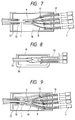
- Fig. 7 is a sectional view showing an example of an optical fiber cord applied to a branching portion of a tape core type coated fiber according to the present invention.
- the optical fiber cord shown in Fig. 7 has a configuration in which each of a tape core type coated fiber 1 and single fibers 4 is coated with a protecting sheath 13 containing therein a reinforcing member 12. An end of the protecting sheath 13 together with the multi-branch pipe B is contained in the reinforcing housing 17 filled with a resin 16.
- reinforcing housing 17 is pipe-like in Fig. 7, it is applicable to facilitate assembling of the inside by such a configuration that the reinforcing housing 17 is replaced by an one-side opening lunch box type reinforcing box 18 provided with a cover 10 as shown in Fig. 8.
- the tape core type coated fiber branching portion A shown in Fig. 2 is configured such that the tape core type coated fiber 1 branched at its forward end into single fibers is inserted from the tape core type coated fiber fixing portion 2 of the multi-branch pipe B shown in Fig. 4A into the protecting sheath 5 of the branching single fibers 4, and the tape core type coated fiber 1 is fixed at the tape core type coated fiber fixing portion 2, so that the branching portion A can be assembled without giving excessive force to the single fibers 4.
- branching portion A shown in Fig. 3 can be housed in the branching portion housing space 3 without fixing the tape core type coated fiber 1 at the branching portion A as shown in Fig. 6.
- the freedom of the tape core type coated fiber increases and the light transmission loss can sufficiently be minimized.
- optical fiber cord branching portion shown in Fig. 7 has a configuration in which the tape core type coated fiber branch portions made as described above are coated with the respective sheaths 13 and the reinforcing housing 17, and then the resin 16 is filled in the reinforcing housing 17. Accordingly, the resin 16 never directly touches the single fibers 4.
- optical fiber cord branching portion shown in Fig. 8 is similar in advantage to that shown in Fig. 7.
- Fig. 9 shows another arrangement of the optical fiber cord branching portion according to the invention.
- This arrangement is similar to the arrangement shown in Fig. 7.
- the reinforcing housing 17 is not filled with a resin.
- the branching portion of the optical fiber cord, an end part of the tape and an end part of each of the sheath 13 are fixedly covered with a heat-shrinkable tubing 19.
- This arrangement is advantageous in that the manufacturing time is shortened relative to the case in which a resin is filled in the housing 17.
- a heat-melting adhesion may be applied to the inner periphery of the heat-shrinkable tubing 19 thereby firmly fixing the branching portion, end part of the tape and end part of the sheath to one another.
- the multi-branch pipe has four branches.
- the invention is not limited thereto or thereby. That is, the multi-branch pipe may have a plurality of branches other than four.
- the single fibers branching from an end of the tape core type coated fiber never touch directly the adhesive or resin, so that stress is never exerted onto the optical fibers in the process of hardening the resin or adhesive, and the light transmission loss never increases in the manufacturing process.
Landscapes
- Physics & Mathematics (AREA)
- General Physics & Mathematics (AREA)
- Optics & Photonics (AREA)
- Mechanical Coupling Of Light Guides (AREA)
- Light Guides In General And Applications Therefor (AREA)
- Insulated Conductors (AREA)
- Optical Fibers, Optical Fiber Cores, And Optical Fiber Bundles (AREA)
Claims (13)
- Eine Verzweigungsvorrichtung für ein beschichtetes Optikfaserkabel vom Bandkerntyp, wobei das Kabel (1) eine Vielzahl von einzelnen Optikfasern (4) als Bestandteil enthält, und die Vorrichtung umfaßt:
eine Schutzeinrichtung (2,3,5,6) zum Einschließen des Kabels an einem Ende, wobei die das Kabel bildenden Fasern sich innerhalb der Schutzeinrichtung verzweigen können, die Schutzeinrichtung eine entsprechende Vielzahl von Ausgangsröhren (B) umfaßt, durch welche die jeweiligen Fasern frei hindurchtreten können, um die Schutzeinrichtung zu verlassen, und wobei die Schutzeinrichtung in ein Harz eingeschlossen ist oder durch eine durch Wärme schrumpfbare Röhre, die einen unter Wärmeeinwirkung schmelzbaren Kleber enthält, eingeschlossen ist. - Die Vorrichtung nach Anspruch 1, wobei das Kabel an der Schutzeinrichtung an ihrem einen Ende befestigt ist.
- Die Vorrichtung nach Anspruch 1, wobei die Schutzeinrichtung eine von dieser vorstehende Röhre (6) enthält, durch welche das Kabel frei hindurchtritt.
- Die Vorrichtung nach Anspruch 1, wobei die Schutzeinrichtung einen Kasten (8) mit Löchern für die Vielzahl von Ausgangsröhren (9) umfaßt.
- Die Vorrichtung nach Anspruch 4, wobei der Kasten (8) mit einer Abdeckung (10) versehen ist.
- Die Vorrichtung nach Anspruch 3, wobei die Röhreneinrichtung (6) darin eine Verstärkungseinrichtung (12, 13) enthält, welche einem innerhalb der Schutzeinrichtung untergebrachten Ende eines optischen Bandkerntypkabels zugeordnet ist.
- Die Vorrichtung nach den Ansprüchen 1 und 6, wobei jede der Röhren (5) mit einer Verstärkungseinrichtung (12) abgedeckt ist, welche innerhalb der Schutzeinrichtung untergebrachten Fasern zugeordnet ist.
- Die Vorrichtung nach Anspruch 1, wobei die Schutzeinrichtung (2,3,5,6) innerhalb eines Gehäuses (17) aufgenommen ist.
- Die Vorrichtung nach Anspruch 8, wobei die Schutzeinrichtung innerhalb des Gehäuses durch Füllen des Gehäuses mit dem Harz gehalten ist.
- Die Vorrichtung nach Anspruch 8 oder 9, wobei das Gehäuse mit einer Abdeckung (10) versehen ist.
- Die Vorrichtung nach Anspruch 8 oder 9, wobei das Gehäuse in der Art einer Lunchbox (18) mit einer offenen Seite ausgebildet ist.
- Die Vorrichtung nach Anspruch 1, wobei eine Optikfaser-Verbindungseinrichtung (7) an dem äußeren Ende von jeder Ausgangsröhre angeordnet ist.
- Die Vorrichtung nach Anspruch 8 oder 9, wobei die Gehäuseeinrichtung vier Zweige umfaßt und wobei die vier Zweige der Gehäuseeinrichtung sich in einer gemeinsamen Ebene oder sich in zwei parallelen Ebenen erstrecken.
Applications Claiming Priority (2)
| Application Number | Priority Date | Filing Date | Title |
|---|---|---|---|
| JP63208667A JPH0797164B2 (ja) | 1988-08-23 | 1988-08-23 | 光ファイバテープ心線の分岐部 |
| JP208667/88 | 1988-08-23 |
Publications (3)
| Publication Number | Publication Date |
|---|---|
| EP0355639A2 EP0355639A2 (de) | 1990-02-28 |
| EP0355639A3 EP0355639A3 (de) | 1991-04-24 |
| EP0355639B1 true EP0355639B1 (de) | 1994-11-02 |
Family
ID=16560059
Family Applications (1)
| Application Number | Title | Priority Date | Filing Date |
|---|---|---|---|
| EP89114966A Expired - Lifetime EP0355639B1 (de) | 1988-08-23 | 1989-08-11 | Ummanteltes faseroptisches Flachbandkabel |
Country Status (4)
| Country | Link |
|---|---|
| US (1) | US4976508A (de) |
| EP (1) | EP0355639B1 (de) |
| JP (1) | JPH0797164B2 (de) |
| DE (1) | DE68919164T2 (de) |
Families Citing this family (44)
| Publication number | Priority date | Publication date | Assignee | Title |
|---|---|---|---|---|
| US5048918A (en) * | 1990-02-07 | 1991-09-17 | Raychem Corporation | Optical fiber cable termination |
| FR2658308B1 (fr) * | 1990-02-09 | 1993-04-09 | Alcatel Cable | Boite de jonction pour cable a fibres optiques, et son procede de montage. |
| US5073044A (en) * | 1990-10-31 | 1991-12-17 | Amp Incorporated | Right angle strain relief for optical fiber connector |
| US5185840A (en) * | 1991-05-06 | 1993-02-09 | Computer Crafts, Inc. | Branching method for a multi-fiber fiberoptic cable |
| JPH04350801A (ja) * | 1991-05-29 | 1992-12-04 | Furukawa Electric Co Ltd:The | 多心被覆光ファイバの分岐部 |
| US5231688A (en) * | 1991-10-07 | 1993-07-27 | Siecor Corporation | Furcation kit |
| GB9210436D0 (en) * | 1992-05-15 | 1992-07-01 | Neave Andrew J | A light projector for use in conjunction with light guides |
| DE4307272C1 (de) * | 1993-03-04 | 1994-04-14 | Siemens Ag | Optisches Verbindungskabel |
| FR2703160B1 (fr) * | 1993-03-26 | 1995-06-02 | Corning Inc | Cassette pour dispositif à fibres optiques, équipée d'un faisceau de tubes souples de protection des fibres. |
| GB9320262D0 (en) * | 1993-10-01 | 1993-11-17 | Bicc Plc | Breakout |
| WO1995015509A1 (de) * | 1993-12-02 | 1995-06-08 | Siemens Aktiengesellschaft | Verbindungseinrichtung und verzweigungseinrichtung für lichtwellenleiterkabel |
| US5892870A (en) * | 1995-11-16 | 1999-04-06 | Fiber Connections Inc. | Fibre optic cable connector |
| US6269212B1 (en) | 1997-09-18 | 2001-07-31 | Pirelli Cavi E Sistemi S.P.A. | Method for performing fixing inside a container for optical connection components |
| EP0903594A1 (de) * | 1997-09-18 | 1999-03-24 | PIRELLI CAVI E SISTEMI S.p.A. | Fixierungsverfahren für optische Verbindungskomponenten innerhalb eines Gehäuses |
| US6618530B1 (en) | 1998-12-02 | 2003-09-09 | 3M Innovative Properties Company | Apparatus for transporting and distributing light using multiple light fibers |
| US6614972B1 (en) | 1998-12-02 | 2003-09-02 | 3M Innovative Properties Company | Coupler for transporting and distributing light to multiple locations with uniform color and intensity |
| US6434315B1 (en) * | 2000-06-23 | 2002-08-13 | Molex Incorporated | Fiber optic connector |
| EP1180706A1 (de) * | 2000-08-14 | 2002-02-20 | Dätwyler Ag Schweizerische Kabel-, Gummi- Und Kunststoffwerke | Vorkonfektioniertes Lichtwellenleiterkabel und Verfahren zur Vorkonfektionierung eines Lichtwellenleiterkabels |
| US6738555B1 (en) * | 2001-03-28 | 2004-05-18 | Corning Cable Systems Llc | Furcation kit |
| US6614971B2 (en) * | 2001-12-04 | 2003-09-02 | Molex Incorporated | Fanout system or apparatus for a fiber optic cable and including a method of fabricating same |
| US6771861B2 (en) | 2002-05-07 | 2004-08-03 | Corning Cable Systems Llc | High performance, flexible optical fiber furcation |
| US7689089B2 (en) | 2006-10-11 | 2010-03-30 | Panduit Corp. | Release latch for pre-terminated cassette |
| US8571367B2 (en) | 2008-06-10 | 2013-10-29 | Tyco Electronics Nederland Bv | Fiber optic furcation assembly |
| US8573855B2 (en) | 2008-10-06 | 2013-11-05 | Adc Telecommunications, Inc. | Fanout cable assembly and method |
| DE102008062535A1 (de) * | 2008-12-16 | 2010-06-17 | Adc Gmbh | Micro-Distribution-Kabel für die optische Nachrichtentechnik und Verfahren zur Herstellung eines Micro-Distribution-Kabels |
| US11251608B2 (en) | 2010-07-13 | 2022-02-15 | Raycap S.A. | Overvoltage protection system for wireless communication systems |
| US8995106B2 (en) | 2011-02-08 | 2015-03-31 | Raycap, S.A. | Overvoltage protection system for wireless communication systems |
| US9099860B2 (en) | 2012-12-10 | 2015-08-04 | Raycap Intellectual Property Ltd. | Overvoltage protection and monitoring system |
| US9640986B2 (en) | 2013-10-23 | 2017-05-02 | Raycap Intellectual Property Ltd. | Cable breakout assembly |
| US10054753B2 (en) | 2014-10-27 | 2018-08-21 | Commscope Technologies Llc | Fiber optic cable with flexible conduit |
| ES2837063T3 (es) * | 2014-11-20 | 2021-06-29 | Prysmian Spa | Dispositivo para conectar un cable óptico y un tubo protector |
| US9575277B2 (en) | 2015-01-15 | 2017-02-21 | Raycap, S.A. | Fiber optic cable breakout assembly |
| AU2015207954C1 (en) | 2015-07-31 | 2022-05-05 | Adc Communications (Australia) Pty Limited | Cable breakout assembly |
| US9971119B2 (en) | 2015-11-03 | 2018-05-15 | Raycap Intellectual Property Ltd. | Modular fiber optic cable splitter |
| US10802237B2 (en) | 2015-11-03 | 2020-10-13 | Raycap S.A. | Fiber optic cable management system |
| WO2017161310A1 (en) | 2016-03-18 | 2017-09-21 | Commscope Technologies Llc | Optic fiber cable fanout conduit arrangements; components, and methods |
| US10890730B2 (en) | 2016-08-31 | 2021-01-12 | Commscope Technologies Llc | Fiber optic cable clamp and clamp assembly |
| WO2018071481A1 (en) | 2016-10-13 | 2018-04-19 | Commscope Technologies Llc | Fiber optic breakout transition assembly incorporating epoxy plug and cable strain relief |
| WO2018136812A1 (en) | 2017-01-20 | 2018-07-26 | Raycap S.A. | Power transmission system for wireless communication systems |
| EP3622336A4 (de) | 2017-05-08 | 2021-01-20 | Commscope Technologies LLC | Glasfaser-breakout-übergangsanordnung |
| CN107167887B (zh) * | 2017-05-16 | 2019-06-11 | 深圳长飞智连技术有限公司 | 一种通配光纤分支模块的极性管理方法 |
| US10971928B2 (en) | 2018-08-28 | 2021-04-06 | Raycap Ip Assets Ltd | Integrated overvoltage protection and monitoring system |
| US11677164B2 (en) | 2019-09-25 | 2023-06-13 | Raycap Ip Assets Ltd | Hybrid antenna distribution unit |
| US12237134B2 (en) | 2021-12-28 | 2025-02-25 | Raycap Ip Assets Ltd | Circuit protection for hybrid antenna distribution units |
Family Cites Families (10)
| Publication number | Priority date | Publication date | Assignee | Title |
|---|---|---|---|---|
| FR2331041A1 (fr) * | 1975-11-05 | 1977-06-03 | Fort Francois | Connecteur pour fibres optiques |
| US4364788A (en) * | 1979-12-17 | 1982-12-21 | Western Electric Company, Inc. | Method of forming a fiber ribbon cable unit |
| DE3024310C2 (de) * | 1980-06-27 | 1983-06-23 | Siemens AG, 1000 Berlin und 8000 München | Optisches Kabel und Verfahren zu seiner Herstellung |
| KR900002554B1 (ko) * | 1982-07-05 | 1990-04-20 | 후루까와 덴끼 고오교오 가부시끼가이샤 | 피복광학섬유 |
| JPS61144611A (ja) * | 1984-12-19 | 1986-07-02 | Ube Nitto Kasei Kk | 強化光フアイバ及びその製造方法 |
| FR2587126B1 (fr) * | 1985-09-09 | 1987-10-23 | Lignes Telegraph Telephon | Dispositif d'eclatement d'un faisceau de fibres optiques en fibres optiques unitaires |
| US4767183A (en) * | 1986-05-12 | 1988-08-30 | Westinghouse Electric Corp. | High strength, heavy walled cable construction |
| US4840454A (en) * | 1986-09-02 | 1989-06-20 | Siemens Aktiengesellschat | Optical cable and method of manufacturing |
| US4744622A (en) * | 1986-09-12 | 1988-05-17 | Amp Incorporated | Optical fiber splice case |
| FR2622024B1 (fr) * | 1987-10-16 | 1990-01-19 | Comp Generale Electricite | Procede de fabrication d'un cable a fibre optique et cable obtenu par ce procede |
-
1988
- 1988-08-23 JP JP63208667A patent/JPH0797164B2/ja not_active Expired - Fee Related
-
1989
- 1989-08-11 DE DE68919164T patent/DE68919164T2/de not_active Expired - Fee Related
- 1989-08-11 EP EP89114966A patent/EP0355639B1/de not_active Expired - Lifetime
- 1989-08-15 US US07/393,938 patent/US4976508A/en not_active Expired - Lifetime
Also Published As
| Publication number | Publication date |
|---|---|
| US4976508A (en) | 1990-12-11 |
| JPH0256505A (ja) | 1990-02-26 |
| EP0355639A3 (de) | 1991-04-24 |
| EP0355639A2 (de) | 1990-02-28 |
| JPH0797164B2 (ja) | 1995-10-18 |
| DE68919164T2 (de) | 1995-03-09 |
| DE68919164D1 (de) | 1994-12-08 |
Similar Documents
| Publication | Publication Date | Title |
|---|---|---|
| EP0355639B1 (de) | Ummanteltes faseroptisches Flachbandkabel | |
| US5970195A (en) | Fiber optic cable furcation unit | |
| EP2275848B1 (de) | Faseroptisches kabel und vergabelungsmodul | |
| US6438299B1 (en) | Assembly and method for furcating optical fibers | |
| EP0506265B1 (de) | Verbindungen optischer Kabel | |
| US6909833B2 (en) | Optical fiber enclosure system using integrated optical connector and coupler assembly | |
| JP4153953B2 (ja) | 光ファイバ・パワー・スプリッタ・モジュール装置 | |
| US4465335A (en) | Concentric core optical fiber coupler | |
| EP1451625B1 (de) | Verzweigungssystem einer vorrichtung für ein faseroptisches kabel und verfahren zur herstellung | |
| EP2216662B1 (de) | Spleißschutzvorrichtung für optische Spleiße und diese enthaltende faseroptische Kabelanordnung | |
| US5905835A (en) | Optical fiber multi-ribbon | |
| EP0889344A1 (de) | Verbindungskabel mit optischem Faserband | |
| JPS63132207A (ja) | 分岐回路およびその製造方法 | |
| US5727102A (en) | Multifiber optical connector for optical ribbon cable | |
| US5425831A (en) | Optical fiber connecting method | |
| WO2004044623A2 (en) | Device having multiple optical fibers | |
| US6231245B1 (en) | Connection between a light guide and a light receiver | |
| EP0422445B1 (de) | Verfahren zur Einkapselung einer optischen Komponente und danach hergestellte gekapselte Komponente | |
| Brown | Fiber Optic Cable Furcation Unit. | |
| JPH02129605A (ja) | 光ファイバ接続部補強収容構造 | |
| Brown et al. | Assembly and Method for Furcating Optical Fibers | |
| GB2329485A (en) | Optical waveguide splice protection tube with coloured strength member | |
| JPH08211259A (ja) | 光ファイバ心線 | |
| HK1091552B (en) | Fiber optic cable and furcation module | |
| JPH01312518A (ja) | 多心、単心変換光コネクタ |
Legal Events
| Date | Code | Title | Description |
|---|---|---|---|
| PUAI | Public reference made under article 153(3) epc to a published international application that has entered the european phase |
Free format text: ORIGINAL CODE: 0009012 |
|
| AK | Designated contracting states |
Kind code of ref document: A2 Designated state(s): DE GB IT |
|
| 17P | Request for examination filed |
Effective date: 19901220 |
|
| PUAL | Search report despatched |
Free format text: ORIGINAL CODE: 0009013 |
|
| AK | Designated contracting states |
Kind code of ref document: A3 Designated state(s): DE GB IT |
|
| 17Q | First examination report despatched |
Effective date: 19920714 |
|
| GRAA | (expected) grant |
Free format text: ORIGINAL CODE: 0009210 |
|
| AK | Designated contracting states |
Kind code of ref document: B1 Designated state(s): DE GB IT |
|
| REF | Corresponds to: |
Ref document number: 68919164 Country of ref document: DE Date of ref document: 19941208 |
|
| ITF | It: translation for a ep patent filed | ||
| PLBE | No opposition filed within time limit |
Free format text: ORIGINAL CODE: 0009261 |
|
| STAA | Information on the status of an ep patent application or granted ep patent |
Free format text: STATUS: NO OPPOSITION FILED WITHIN TIME LIMIT |
|
| 26N | No opposition filed | ||
| REG | Reference to a national code |
Ref country code: GB Ref legal event code: IF02 |
|
| PGFP | Annual fee paid to national office [announced via postgrant information from national office to epo] |
Ref country code: GB Payment date: 20020807 Year of fee payment: 14 |
|
| PGFP | Annual fee paid to national office [announced via postgrant information from national office to epo] |
Ref country code: DE Payment date: 20020816 Year of fee payment: 14 |
|
| PG25 | Lapsed in a contracting state [announced via postgrant information from national office to epo] |
Ref country code: GB Free format text: LAPSE BECAUSE OF NON-PAYMENT OF DUE FEES Effective date: 20030811 |
|
| PG25 | Lapsed in a contracting state [announced via postgrant information from national office to epo] |
Ref country code: DE Free format text: LAPSE BECAUSE OF NON-PAYMENT OF DUE FEES Effective date: 20040302 |
|
| GBPC | Gb: european patent ceased through non-payment of renewal fee |
Effective date: 20030811 |
|
| PG25 | Lapsed in a contracting state [announced via postgrant information from national office to epo] |
Ref country code: IT Free format text: LAPSE BECAUSE OF NON-PAYMENT OF DUE FEES Effective date: 20050811 |