EP0355283A1 - Schneidleiste - Google Patents
Schneidleiste Download PDFInfo
- Publication number
- EP0355283A1 EP0355283A1 EP89110134A EP89110134A EP0355283A1 EP 0355283 A1 EP0355283 A1 EP 0355283A1 EP 89110134 A EP89110134 A EP 89110134A EP 89110134 A EP89110134 A EP 89110134A EP 0355283 A1 EP0355283 A1 EP 0355283A1
- Authority
- EP
- European Patent Office
- Prior art keywords
- cutting
- cutting bar
- bar
- cutter
- wall
- Prior art date
- Legal status (The legal status is an assumption and is not a legal conclusion. Google has not performed a legal analysis and makes no representation as to the accuracy of the status listed.)
- Granted
Links
Images
Classifications
-
- B—PERFORMING OPERATIONS; TRANSPORTING
- B23—MACHINE TOOLS; METAL-WORKING NOT OTHERWISE PROVIDED FOR
- B23D—PLANING; SLOTTING; SHEARING; BROACHING; SAWING; FILING; SCRAPING; LIKE OPERATIONS FOR WORKING METAL BY REMOVING MATERIAL, NOT OTHERWISE PROVIDED FOR
- B23D51/00—Sawing machines or sawing devices working with straight blades, characterised only by constructional features of particular parts; Carrying or attaching means for tools, covered by this subclass, which are connected to a carrier at both ends
- B23D51/02—Sawing machines or sawing devices working with straight blades, characterised only by constructional features of particular parts; Carrying or attaching means for tools, covered by this subclass, which are connected to a carrier at both ends of beds; of guiding arrangements for work-tables or saw carriers; of frames
- B23D51/025—Sawing machines or sawing devices working with straight blades, characterised only by constructional features of particular parts; Carrying or attaching means for tools, covered by this subclass, which are connected to a carrier at both ends of beds; of guiding arrangements for work-tables or saw carriers; of frames of arrangements for guiding the saw blade
-
- A—HUMAN NECESSITIES
- A01—AGRICULTURE; FORESTRY; ANIMAL HUSBANDRY; HUNTING; TRAPPING; FISHING
- A01F—PROCESSING OF HARVESTED PRODUCE; HAY OR STRAW PRESSES; DEVICES FOR STORING AGRICULTURAL OR HORTICULTURAL PRODUCE
- A01F25/00—Storing agricultural or horticultural produce; Hanging-up harvested fruit
- A01F25/16—Arrangements in forage silos
- A01F25/20—Unloading arrangements
- A01F25/2027—Unloading arrangements for trench silos
- A01F25/2036—Cutting or handling arrangements for silage blocks
-
- B—PERFORMING OPERATIONS; TRANSPORTING
- B26—HAND CUTTING TOOLS; CUTTING; SEVERING
- B26D—CUTTING; DETAILS COMMON TO MACHINES FOR PERFORATING, PUNCHING, CUTTING-OUT, STAMPING-OUT OR SEVERING
- B26D1/00—Cutting through work characterised by the nature or movement of the cutting member or particular materials not otherwise provided for; Apparatus or machines therefor; Cutting members therefor
- B26D1/0006—Cutting members therefor
-
- B—PERFORMING OPERATIONS; TRANSPORTING
- B26—HAND CUTTING TOOLS; CUTTING; SEVERING
- B26D—CUTTING; DETAILS COMMON TO MACHINES FOR PERFORATING, PUNCHING, CUTTING-OUT, STAMPING-OUT OR SEVERING
- B26D1/00—Cutting through work characterised by the nature or movement of the cutting member or particular materials not otherwise provided for; Apparatus or machines therefor; Cutting members therefor
- B26D1/01—Cutting through work characterised by the nature or movement of the cutting member or particular materials not otherwise provided for; Apparatus or machines therefor; Cutting members therefor involving a cutting member which does not travel with the work
- B26D1/04—Cutting through work characterised by the nature or movement of the cutting member or particular materials not otherwise provided for; Apparatus or machines therefor; Cutting members therefor involving a cutting member which does not travel with the work having a linearly-movable cutting member
- B26D1/06—Cutting through work characterised by the nature or movement of the cutting member or particular materials not otherwise provided for; Apparatus or machines therefor; Cutting members therefor involving a cutting member which does not travel with the work having a linearly-movable cutting member wherein the cutting member reciprocates
- B26D1/10—Cutting through work characterised by the nature or movement of the cutting member or particular materials not otherwise provided for; Apparatus or machines therefor; Cutting members therefor involving a cutting member which does not travel with the work having a linearly-movable cutting member wherein the cutting member reciprocates in, or substantially in, a direction parallel to the cutting edge
- B26D1/11—Cutting through work characterised by the nature or movement of the cutting member or particular materials not otherwise provided for; Apparatus or machines therefor; Cutting members therefor involving a cutting member which does not travel with the work having a linearly-movable cutting member wherein the cutting member reciprocates in, or substantially in, a direction parallel to the cutting edge with a plurality of cutting members
-
- B—PERFORMING OPERATIONS; TRANSPORTING
- B26—HAND CUTTING TOOLS; CUTTING; SEVERING
- B26D—CUTTING; DETAILS COMMON TO MACHINES FOR PERFORATING, PUNCHING, CUTTING-OUT, STAMPING-OUT OR SEVERING
- B26D1/00—Cutting through work characterised by the nature or movement of the cutting member or particular materials not otherwise provided for; Apparatus or machines therefor; Cutting members therefor
- B26D1/0006—Cutting members therefor
- B26D2001/0033—Cutting members therefor assembled from multiple blades
-
- B—PERFORMING OPERATIONS; TRANSPORTING
- B26—HAND CUTTING TOOLS; CUTTING; SEVERING
- B26D—CUTTING; DETAILS COMMON TO MACHINES FOR PERFORATING, PUNCHING, CUTTING-OUT, STAMPING-OUT OR SEVERING
- B26D1/00—Cutting through work characterised by the nature or movement of the cutting member or particular materials not otherwise provided for; Apparatus or machines therefor; Cutting members therefor
- B26D1/0006—Cutting members therefor
- B26D2001/006—Cutting members therefor the cutting blade having a special shape, e.g. a special outline, serrations
Definitions
- the innovation relates to a cutting bar with a saw blade-like cutting edge for use in counter-rotating double-cutting tools of silage crop cutters.
- Double-cutting tools of conventional design are usually designed so that a cutting bar is fixedly attached to the support frame of the silage crop cutter and another mostly front cutting bar is installed reciprocally in the horizontal direction for this purpose. It is also known to use cutting strips which can be moved in opposite directions in a double cutting tool.
- the front cutting bars are regularly different in design, height and weight from the rear cutting bars; The pressure force is also transmitted from the support frame to the cutting bars mostly in the area of the cutting bar holder and guide and thus leads to an uneven pressure load on the cutting bars.
- the object of the invention is therefore to demonstrate cutting strips which, due to the same design, enable uniform pressure transmission from the supporting frame to the cutting strips.
- the cutting bar on its inner wall facing the counter-cutting bar has a shoulder arranged above the cutting edge, the upper inner cutting bar wall being offset on the shoulder edge by the shoulder width in the direction of the outer cutting bar wall.
- the use of mirror-identical cutting strips is provided in order to achieve the greatest possible design of the cutting strips.
- the lower edge of a support frame center web can be transferred evenly to the cutting strips for pressure transmission into the heel edges of the cutting strips attached to both sides of the cutting strips.
- the pressure of up to about 11 t generated by a working cylinder during a cutting process for penetrating the cutting tools into the silage on the supporting frame frame is distributed over a substantially larger area. This ensures a uniformly effective pressure at all points of the cutting bars and the material stress within the cutting bars is achieved by a relative pressure reduction per unit area.
- the cutting strips 1 and 1 ' which are mirror images of one another in cross section in FIG. 1, face towards their mutually facing inner cutting strip wall half of their cutting edges 2 has a heel edge 3 pointing in the direction of the outer cutting bar wall 5.
- These shoulder edges 3 serve to engage the lower edge of the supporting frame and ensure a uniform distribution of the pressure exerted on them by the supporting frame during the cutting process in the silage.
- the groove-shaped recesses 6 serve to accommodate fasteners for guiding and holding the cutting strips on the support frame.
- the corner connection detail of a cutting bar 1 shown in FIG. 2 has cutouts in the form of toothings 9 on one side. These serrations are used to accommodate power transmission arms, which, depending on whether the cutting bar is used as an inner or outer cutting bar within a double cutting tool, have mutually complementary recesses, so that engagement of the power transmission lever can take place in a superimposed manner and ensure the same overall height of the two cutting bars is.
- the illustrated embodiment of a cantilevered head 7 of a connecting bolt represents a possibility of guiding the cutting strips relative to the central webs of the supporting frames which support them, the lateral play of the cutting strips being limited by the respective groove ends 6.
Landscapes
- Engineering & Computer Science (AREA)
- Mechanical Engineering (AREA)
- Life Sciences & Earth Sciences (AREA)
- Forests & Forestry (AREA)
- Environmental Sciences (AREA)
- Threshing Machine Elements (AREA)
- Auxiliary Devices For Machine Tools (AREA)
- Crushing And Pulverization Processes (AREA)
- Finish Polishing, Edge Sharpening, And Grinding By Specific Grinding Devices (AREA)
- Apparatuses For Bulk Treatment Of Fruits And Vegetables And Apparatuses For Preparing Feeds (AREA)
- Mechanical Treatment Of Semiconductor (AREA)
Abstract
Description
- Die Neuerung betrifft eine Schneidleiste mit sägeblattartig ausgestalteter Schneide zur Verwendung in gegenläufigen Doppelschneidewerkzeugen von Silagegutschneidegeräten.
- Doppelschneidewerkzeuge herkömmlicher Bauart sind üblicherweise so konzipiert, daß eine Schneidleiste am Tragrahmen des Silagegutschneidegerätes feststehend angebracht ist und eine weitere zumeist vordere Schneidleiste hierzu in wagerechter Richtung hin- und herbeweglich installiert ist. Auch ist die Verwendung gegenläufig bewegbarer Schneidleisten in einem Doppelschneidewerkzeug bekannt. Dabei sind die vorderen Schneidleisten jedoch gegenüber den hinteren Schneidleisten regelmäßig unterschiedlich in Bezug auf technische Beschaffenheit, Bauhöhe und Gewicht ausgestaltet; auch erfolgt die Druckkraftübertragung von Tragrahmen auf Schneidleisten zumeist für im Bereich der Schneidleistenhalterung und -führung und führt dadurch zu einer ungleichmäßigen Druckbeanspruchung der Schneidleisten.
- Aufgabe der Erfindung ist es daher, Schneidleisten nachzuweisen, die aufgrund gleicher Bauart eine gleichmäßige Druckübertragung von den Tragrahmen auf die Schneidleisten ermöglichen.
- Diese Aufgabe wird erfindungsgemäß dadurch gelöst, daß die Schneidleiste an ihrer inneren zur Gegenschneidleiste gerichteten Wand einen oberhalb der Schneide angeordneten Absatz aufweist, wobei die obere innere Schneidleistenwand an der Absatzkante um die Absatzbreite in Richtung der äußeren Schneidleistenwand versetzt ist.
- Dabei ist zum Erreichen einer möglichst weitgehenden Bauart Gleicheit der Schneidleisten die Verwendung spiegelbildlich gleicher Schneidleisten vorgesehen. Die Unterkante eines Tragrahmenmittelsteges kann zur Druckübertragung in die Absatzkanten der beidseitig an ihr angebrachten Schneidleisten gleichmäßig auf die Schneidleisten übertragen werden. Hierdurch wird der bei einem Schneidevorgang zum Eindringen der Schneidwerkzeuge in die Silage auf das Tragrahmengestell von einem Arbeitszylinder erzeugte Druck von bis zu etwa 11 t auf eine wesentlich größere Fläche verteilt. Damit wird ein gleichmäßig an allen Stellen der Schneidleisten wirksamer Druck gewährleistet und die Materialbeanspruchung innerhalb der Schneidleisten durch eine relative Druckverminderung je Flächeneinheit erreicht.
- Ein Ausführungsbeispiel der Erfindung ist in der Zeichnung dargestellt und wird im foglenden näher beschrieben. Es zeigen:
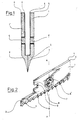
- Figur 1 einen Querschnitt durch zwei einander spiegelbildlich gegenüberstehende Schneidleisten entlang der Achse A - A in Figur 2;
- Figur 2 eine perspektivische Darstellung eines Eckverbindungsdetails der Schneidleiste.
- Die Schneidleisten 1 und 1′, die sich in Figur 1 spiegelbildlich im Querschnitt gegenüberstehen, weisen zu ihrer einander zuweisenden inneren Schneidleistenwand ober halb ihrer Schneiden 2 eine in Richtung äußerer Schneidleistenwand 5 weisende Absatzkante 3 auf. Diese Absatzkanten 3 dienen dem Eingreifen der Tragrahmenunterkante und gewährleisten eine gleichmäßige Verteilung des bei dem Schneidevorgang in der Silage vom Traggestell auf sie ausgeübten Druckes. Die nutförmigen Aussparungen 6 dienen der Aufnahme von Befestigungsmitteln zur Führung und Halterung der Schneidleisten am Tragrahmen.
- Das in Figur 2 dargestellte Eckverbindungsdetail einer Schneidleiste 1 weist an seiner einen Seite Aussparungen in Form von Verzahnungen 9 auf. Diese Verzahnungen dienen der Aufnahme von Kraftübertragungsarmen, die, je nachdem ob die Schneidleiste als innere oder äußere Schneidleiste innerhalb eines Doppelschneidewerkzeuges Verwendung findet, einander ergänzende Aussparungen aufweisen, so daß ein Eingreifen der Kraftübertragungshebel in einander überlagerter Weise geschehen kann und eine gleiche Bauhöhenausführung beider Schneidleisten gewährleistet ist. Die dargestellte Ausführungsform eines überkragenden Kopfes 7 eines Verbindungsbolzens stellt eine Möglichkeit dar, die Schneidleisten gegenüber den sie tragenden Mittelstegen der Tragrahmen zu führen, wobei das seitliche Spiel der Schneidleisten durch die jeweiligen Nutenden 6 begrenzt ist.
Claims (5)
dadurch gekennzeichnet, daß die Schneidleiste (1) an ihrer inneren zur Gegenschneidleiste (1′) gerichteten Wand einen oberhalb der Schneide (2) angeordneten Absatz (3) aufweist, wobei die obere innere Schneidleistenwand an der Absatzkante (3) um die Absatzbreite in Richtung der äußeren Schneidleistenwand (5) versetzt ist.
dadurch gekennzeichnet, daß die Schneidleiste (1) gegenüber der mit ihr gegenläufig arbeitenden Schneidleiste (1′) in ihrem Querschnitt zumindest im Bereich der Schneide (2) sowie des Absatzes (3) spiegelbildlich ausgestaltet ist.
dadurch gekennzeichnet, daß die Schneidleiste (1) an ihrem einen Ende mit je einem Arm zur Verbindung mit einem Antriebsorgan ausgestattet ist.
dadurch gekennzeichnet, daß die Schneidleiste (1) Führungsnuten (6) in Form langlochartiger Aussparungen zur Aufnahme von gleichzeitig die Schneidleistenführung darstellenden Verbindungsbolzen aufweist.
Priority Applications (1)
| Application Number | Priority Date | Filing Date | Title |
|---|---|---|---|
| AT89110134T ATE89447T1 (de) | 1988-07-09 | 1989-06-05 | Schneidleiste. |
Applications Claiming Priority (2)
| Application Number | Priority Date | Filing Date | Title |
|---|---|---|---|
| DE8808867U DE8808867U1 (de) | 1988-07-09 | 1988-07-09 | Schneidleiste |
| DE8808867U | 1988-07-09 |
Publications (2)
| Publication Number | Publication Date |
|---|---|
| EP0355283A1 true EP0355283A1 (de) | 1990-02-28 |
| EP0355283B1 EP0355283B1 (de) | 1993-05-19 |
Family
ID=6825853
Family Applications (1)
| Application Number | Title | Priority Date | Filing Date |
|---|---|---|---|
| EP89110134A Expired - Lifetime EP0355283B1 (de) | 1988-07-09 | 1989-06-05 | Schneidleiste |
Country Status (7)
| Country | Link |
|---|---|
| EP (1) | EP0355283B1 (de) |
| JP (1) | JPH03104508A (de) |
| AT (1) | ATE89447T1 (de) |
| DE (2) | DE8808867U1 (de) |
| DK (1) | DK334589A (de) |
| HU (1) | HUT52723A (de) |
| IE (1) | IE892201L (de) |
Citations (4)
| Publication number | Priority date | Publication date | Assignee | Title |
|---|---|---|---|---|
| FR2087999A1 (en) * | 1970-05-04 | 1972-01-07 | Brunetti Adelmo | Cutter bar - with nylon friction shoe |
| EP0255024A1 (de) * | 1986-07-23 | 1988-02-03 | Firma Bernard van Lengerich Maschinenfabrik GmbH & Co. | Silagegutschneider mit einem L- oder U-förmigen Tragrahmen |
| DE8812574U1 (de) * | 1988-10-06 | 1988-11-24 | Fella-Werke Gmbh, 8501 Feucht | Vorrichtung zum Schneiden von Silageblöcken |
| EP0337089A1 (de) * | 1988-04-09 | 1989-10-18 | von der Heide, Hans | Silagegutschneidegerät mit U-förmigem Tragerahmen |
-
1988
- 1988-07-09 DE DE8808867U patent/DE8808867U1/de not_active Expired
-
1989
- 1989-06-05 EP EP89110134A patent/EP0355283B1/de not_active Expired - Lifetime
- 1989-06-05 DE DE8989110134T patent/DE58904403D1/de not_active Expired - Fee Related
- 1989-06-05 AT AT89110134T patent/ATE89447T1/de not_active IP Right Cessation
- 1989-07-06 DK DK334589A patent/DK334589A/da not_active Application Discontinuation
- 1989-07-07 IE IE892201A patent/IE892201L/xx unknown
- 1989-07-07 HU HU893444A patent/HUT52723A/hu unknown
- 1989-07-10 JP JP1177837A patent/JPH03104508A/ja active Pending
Patent Citations (4)
| Publication number | Priority date | Publication date | Assignee | Title |
|---|---|---|---|---|
| FR2087999A1 (en) * | 1970-05-04 | 1972-01-07 | Brunetti Adelmo | Cutter bar - with nylon friction shoe |
| EP0255024A1 (de) * | 1986-07-23 | 1988-02-03 | Firma Bernard van Lengerich Maschinenfabrik GmbH & Co. | Silagegutschneider mit einem L- oder U-förmigen Tragrahmen |
| EP0337089A1 (de) * | 1988-04-09 | 1989-10-18 | von der Heide, Hans | Silagegutschneidegerät mit U-förmigem Tragerahmen |
| DE8812574U1 (de) * | 1988-10-06 | 1988-11-24 | Fella-Werke Gmbh, 8501 Feucht | Vorrichtung zum Schneiden von Silageblöcken |
Also Published As
| Publication number | Publication date |
|---|---|
| HUT52723A (en) | 1990-08-28 |
| EP0355283B1 (de) | 1993-05-19 |
| DK334589D0 (da) | 1989-07-06 |
| JPH03104508A (ja) | 1991-05-01 |
| DE8808867U1 (de) | 1988-09-15 |
| DK334589A (da) | 1990-01-10 |
| DE58904403D1 (de) | 1993-06-24 |
| IE892201L (en) | 1990-01-09 |
| ATE89447T1 (de) | 1993-06-15 |
Similar Documents
| Publication | Publication Date | Title |
|---|---|---|
| EP1551214B1 (de) | Mähbalken | |
| EP1429597B1 (de) | Mähmesser mit einer aus teilschienen zusammengesetzten messerschiene | |
| EP0093318A2 (de) | Entschwartungsmaschine | |
| EP0575393B1 (de) | Blechbiegevorrichtung | |
| EP0913139B1 (de) | Modulares OP-Tischsystem | |
| DE4416522A1 (de) | Papierbahn-Schneideeinrichtung | |
| EP1008289A1 (de) | Messerschnellwechseleinrichtung für Mähwerke | |
| EP0557866B1 (de) | Schere zum Trennen von Schrott | |
| EP0008483A1 (de) | Langhaarscherteil, insbesondere für Trockenrasierapparate | |
| EP0355283A1 (de) | Schneidleiste | |
| DE3218673A1 (de) | Maehmesserantrieb fuer eine halmfruchterntemaschine | |
| DE2948634C2 (de) | Mähmesser für Fingerbalkenmähwerke | |
| EP1099481A1 (de) | Zerkleinerungsmaschine | |
| DE3529903A1 (de) | Bandsaege | |
| DE3120897A1 (de) | "presse zum herstellen von holmen oder platten aus verleimten staeben" | |
| EP0068305A1 (de) | Gerät zum Entnehmen von Futterportionen aus Flach- oder Fahrsilos | |
| DE3587803T2 (de) | Ladegerät mit einer seitlich schneidenden Vorrichtung für Siloentnahme- und Verteilergeräte. | |
| DE4041802C1 (de) | ||
| DE3613647C2 (de) | ||
| DE1627147A1 (de) | Schneidmaschine fuer Metallplatten | |
| DD235013A1 (de) | Einzugsfoerderkanal fuer maehdrescher | |
| DE102009024523A1 (de) | Bandsägemaschine mit einem Sägerahmen mit Sägeband | |
| AT280846B (de) | Scherkopf für Trockenrasierapparate | |
| DE3644876A1 (de) | Vorrichtung zum schneiden von silagebloecken | |
| DE3712021C2 (de) | Gerät zum Entnehmen von Silagegut |
Legal Events
| Date | Code | Title | Description |
|---|---|---|---|
| PUAI | Public reference made under article 153(3) epc to a published international application that has entered the european phase |
Free format text: ORIGINAL CODE: 0009012 |
|
| AK | Designated contracting states |
Kind code of ref document: A1 Designated state(s): AT BE CH DE ES FR GB IT LI NL SE |
|
| 17P | Request for examination filed |
Effective date: 19900726 |
|
| 17Q | First examination report despatched |
Effective date: 19910925 |
|
| GRAA | (expected) grant |
Free format text: ORIGINAL CODE: 0009210 |
|
| AK | Designated contracting states |
Kind code of ref document: B1 Designated state(s): AT BE CH DE ES FR GB IT LI NL SE |
|
| PG25 | Lapsed in a contracting state [announced via postgrant information from national office to epo] |
Ref country code: IT Free format text: LAPSE BECAUSE OF FAILURE TO SUBMIT A TRANSLATION OF THE DESCRIPTION OR TO PAY THE FEE WITHIN THE PRE;WARNING: LAPSES OF ITALIAN PATENTS WITH EFFECTIVE DATE BEFORE 2007 MAY HAVE OCCURRED AT ANY TIME BEFORE 2007. THE CORRECT EFFECTIVE DATE MAY BE DIFFERENT FROM THE ONE RECORDED.SCRIBED TIME-LIMIT Effective date: 19930519 Ref country code: ES Free format text: THE PATENT HAS BEEN ANNULLED BY A DECISION OF A NATIONAL AUTHORITY Effective date: 19930519 Ref country code: FR Effective date: 19930519 Ref country code: SE Effective date: 19930519 Ref country code: GB Effective date: 19930519 |
|
| REF | Corresponds to: |
Ref document number: 89447 Country of ref document: AT Date of ref document: 19930615 Kind code of ref document: T |
|
| PG25 | Lapsed in a contracting state [announced via postgrant information from national office to epo] |
Ref country code: AT Effective date: 19930605 |
|
| REF | Corresponds to: |
Ref document number: 58904403 Country of ref document: DE Date of ref document: 19930624 |
|
| PG25 | Lapsed in a contracting state [announced via postgrant information from national office to epo] |
Ref country code: BE Effective date: 19930630 Ref country code: CH Effective date: 19930630 Ref country code: LI Effective date: 19930630 |
|
| EN | Fr: translation not filed | ||
| GBV | Gb: ep patent (uk) treated as always having been void in accordance with gb section 77(7)/1977 [no translation filed] |
Effective date: 19930519 |
|
| BERE | Be: lapsed |
Owner name: VON DER HEIDE HANS Effective date: 19930630 |
|
| PG25 | Lapsed in a contracting state [announced via postgrant information from national office to epo] |
Ref country code: NL Effective date: 19940101 |
|
| NLV4 | Nl: lapsed or anulled due to non-payment of the annual fee | ||
| REG | Reference to a national code |
Ref country code: CH Ref legal event code: PL |
|
| PG25 | Lapsed in a contracting state [announced via postgrant information from national office to epo] |
Ref country code: DE Effective date: 19940301 |
|
| PLBE | No opposition filed within time limit |
Free format text: ORIGINAL CODE: 0009261 |
|
| STAA | Information on the status of an ep patent application or granted ep patent |
Free format text: STATUS: NO OPPOSITION FILED WITHIN TIME LIMIT |
|
| 26N | No opposition filed |