EP0354446A1 - Innengewinde-Befestigungselement - Google Patents
Innengewinde-Befestigungselement Download PDFInfo
- Publication number
- EP0354446A1 EP0354446A1 EP89114175A EP89114175A EP0354446A1 EP 0354446 A1 EP0354446 A1 EP 0354446A1 EP 89114175 A EP89114175 A EP 89114175A EP 89114175 A EP89114175 A EP 89114175A EP 0354446 A1 EP0354446 A1 EP 0354446A1
- Authority
- EP
- European Patent Office
- Prior art keywords
- bore
- internal thread
- segment
- fastening element
- thread
- Prior art date
- Legal status (The legal status is an assumption and is not a legal conclusion. Google has not performed a legal analysis and makes no representation as to the accuracy of the status listed.)
- Granted
Links
- 238000004804 winding Methods 0.000 claims abstract description 3
- 230000006378 damage Effects 0.000 description 3
- 238000005553 drilling Methods 0.000 description 2
- 208000027418 Wounds and injury Diseases 0.000 description 1
- 230000015572 biosynthetic process Effects 0.000 description 1
- 238000005266 casting Methods 0.000 description 1
- 238000001125 extrusion Methods 0.000 description 1
- 208000014674 injury Diseases 0.000 description 1
- 238000003780 insertion Methods 0.000 description 1
- 230000037431 insertion Effects 0.000 description 1
- 238000000034 method Methods 0.000 description 1
- 238000000465 moulding Methods 0.000 description 1
- 238000004080 punching Methods 0.000 description 1
- 238000010079 rubber tapping Methods 0.000 description 1
- 238000007493 shaping process Methods 0.000 description 1
Images
Classifications
-
- F—MECHANICAL ENGINEERING; LIGHTING; HEATING; WEAPONS; BLASTING
- F16—ENGINEERING ELEMENTS AND UNITS; GENERAL MEASURES FOR PRODUCING AND MAINTAINING EFFECTIVE FUNCTIONING OF MACHINES OR INSTALLATIONS; THERMAL INSULATION IN GENERAL
- F16B—DEVICES FOR FASTENING OR SECURING CONSTRUCTIONAL ELEMENTS OR MACHINE PARTS TOGETHER, e.g. NAILS, BOLTS, CIRCLIPS, CLAMPS, CLIPS OR WEDGES; JOINTS OR JOINTING
- F16B37/00—Nuts or like thread-engaging members
-
- Y—GENERAL TAGGING OF NEW TECHNOLOGICAL DEVELOPMENTS; GENERAL TAGGING OF CROSS-SECTIONAL TECHNOLOGIES SPANNING OVER SEVERAL SECTIONS OF THE IPC; TECHNICAL SUBJECTS COVERED BY FORMER USPC CROSS-REFERENCE ART COLLECTIONS [XRACs] AND DIGESTS
- Y10—TECHNICAL SUBJECTS COVERED BY FORMER USPC
- Y10S—TECHNICAL SUBJECTS COVERED BY FORMER USPC CROSS-REFERENCE ART COLLECTIONS [XRACs] AND DIGESTS
- Y10S411/00—Expanded, threaded, driven, headed, tool-deformed, or locked-threaded fastener
- Y10S411/924—Coupled nut and bolt
Definitions
- the invention relates to an internally threaded fastener having a body having an internally threaded bore having at least one open end for receiving an externally threaded fastener.
- male threaded fasteners such as machine screws, bolts, and pins
- female threaded fasteners such as nuts or internally threaded holes.
- Thread crossing can damage the threads of both one and the other fastener and cause the fasteners to seize. If such a fastener combination is seized, it can not continue to tighten, resulting in unsafe attachment and a variety of possible accidents, such as personal injury or equipment damage.
- a seized fastener combination is difficult to loosen and the fastener threads are damaged if the fasteners are separated.
- the invention has for its object to provide an internal thread fastener of the generic type that prevents thread crossing and related problems.
- this internal thread fastening element is intended to ensure that when an external thread fastening element is screwed into the internal thread fastening element, the threads of both elements are in phase with one another, so that the fastening elements can be screwed together without thread crossover.
- this object is achieved in that a thread-free lip segment is formed in one open end.
- a mouth can be formed at one end of the bore and has the lip segment. With a continuous bore, the mouth can also be formed at both ends.
- the mouth is preferably non-circular and has a partial turn segment in the unthreaded lip segment.
- the partial turn segment adjoins the internal thread of the bore and has at least one partial turn with the same pitch as the internal thread of the bore.
- two partial turns are formed in the partial turn segment of the bore mouth, of which the first partial turn is near the opening of the hole approximately mouth and is a circumferential length of about 15 to about 60% of the diameter of the bore and the second partial turn is close to the first partial turn and has a circumferential length of about 20 to about 70% of the diameter of the bore.
- the lip segment is preferably inclined radially outward away from the central axis of the bore, the angle of inclination preferably being between approximately 2 to approximately 10 ° with respect to the central axis of the bore and preferably being approximately 5 °.
- the internal thread fastening element shown in FIGS. 1 to 4 is a nut.
- the invention is also applicable to another internal thread fastening element which has a bore with an internal thread that is open at at least one end.
- An internally threaded fastener for example the nut 10 shown in FIGS. 1 to 4, has a body 20 with a bore 22.
- the bore 22 can the body 20th enforce completely, as is the case with the illustrated mother, or extend only through part of the body 20.
- the bore has at least one open end 24 for receiving an external thread fastening element, for example a screw, a threaded bolt or threaded pin.
- a mouth 26 is provided in at least one of the open ends 24 and has a partial winding segment 30 and a lip segment 40.
- the mouth 26 is not circular, such as the largely oval shape shown in FIGS. 1 and 2.
- a circular mouth shape and a plurality of non-circular mouth shapes can also be provided in connection with the present invention.
- the partial turn segment 30 of the mouth 26 adjoins the bore 22 and is provided on the inside with a partial turn, the pitch of which is equal to that of the bore.
- Two partial turns are preferably provided in the partial turn segment 30.
- the first partial turn 32 is near the open end of the bore 22 and has a circumferential length that is about 15 to about 65% of the diameter of the bore 22.
- the second partial turn 34 is proximate to the first partial turn and has a circumferential length of about 20 to 70% of the diameter of the bore 22.
- the first partial turn 32 has a circumferential length of about 25 to about 40% of the diameter of the bore 22 and the second Partial turn 34 has a circumferential length of about 30 to about 50% of the diameter of the bore 22.
- the lip segment 40 is formed in the mouth 26 opposite the partial turn segment 30.
- the lip segment 40 is thread-free.
- the lip segment 40 preferably has a curved shape; however, other shapes are within the scope of the invention, provided that no threads are formed therein.
- the lip segment 40 is inclined radially outward from the central axis A-A of the bore 22, as shown in FIG. 2.
- the angle of inclination is between about 2 to about 10 ° with respect to the central axis A-A of the bore 22, which is shown in Fig. 2.
- the angle of inclination is preferably approximately 5 ° with respect to the central axis A-A of the bore 22.
- the internal thread fastening element according to the invention can be produced in a wide variety of ways. So a body, e.g. a mother, in the casting or extrusion process in a manner known per se.
- the molding tool or die used to shape the body can be shaped so that the lip segment is formed simultaneously with the shaping of the body.
- the lip segment can be formed in the mouth of the bore after the body has been manufactured by drilling the body at a point offset from the central axis of the bore or by using a piercing or striking tool at that point. The hole can then be threaded by tapping. Where the lip segment extends radially outward from the central axis of the bore, no thread is formed in the lip segment.
- the lip segment can be formed by drilling or punching after the thread has been formed in the bore.
- the internal thread fastening element prevents thread crossover by the formation of the thread-free lip segment 40, since the lip segment guides an external thread fastening element when it is inserted into the internal thread fastening element and causes the thread of the external thread fastening element to be positioned next to at least the one partial turn, so that the thread of the external thread attachment elements is in phase with the thread of the internal thread fastener.
- the fasteners can then be screwed together.
- the invention therefore offers the advantage over the prior art that it eliminates the need for very careful insertion and alignment of the threads of the internal thread and external thread fasteners before they are screwed together using machine tools, and the problems of thread crossover, which can occur even when conventional fasteners are carefully plugged together , reduced to a minimum.
Abstract
Description
- Die Erfindung bezieht sich auf ein Innengewinde-Befestigungselement mit einem Körper, der eine mit Innengewinde versehene Bohrung aufweist, die wenigstens ein offenes Ende zur Aufnahme eines Außengewinde-Befestigungselements aufweist.
- Außengewinde-Befestigungselemente, z.B. Maschinenschrauben, Bolzen und Stifte, werden gewöhnlich zusammen mit entsprechend bemessenen Innengewinde-Befestigungselementen, z.B. Muttern oder mit Innengewinde versehenen Bohrungen, verwendet. Wenn diese Befestigungsmittel miteinander in Eingriff gebracht werden sollen, muß sorgfältig darauf geachtet werden, daß sie genau miteinander fluchten, da andernfalls eine Gewindeüberkreuzung auftreten kann, wenn sie zusammengeschraubt werden. Eine Gewindeüberkreuzung kann zu einer Beschädigung des Gewindes sowohl des einen als auch des anderen Befestigungselements und dazu führen, daß sich die Befestigungselemente festfressen. Wenn sich eine solche Befestigungselemente-Kombination festgefressen hat, läßt sie sich nicht weiter festziehen, so daß sich eine unsichere Befestigung und eine Vielzahl möglicher Unfälle ergibt, z.B. eine Verletzung von Personen oder Beschädigung von Einrichtungen. Darüber hinaus ist eine festgefressene Befestigungselemente-Kombination schwierig zu lösen, und die Gewinde der Befestigungselemente werden beschädigt, wenn die Befestigungselemente getrennt werden.
- Der Erfindung liegt die Aufgabe zugrunde, ein Innengewinde-Befestigungselement der gattungsgemäßen Art anzugeben, das eine Gewindeüberkreuzung und damit verbundene Probleme verhindert. Insbesondere soll dieses Innengewinde-Befestigungselement sicherstellen, daß beim Einschrauben eines Außengewinde-Befestigungselements in das Innengewinde-Befestigungselement die Gewinde beider Elemente miteinander in Phase sind, so daß sich die Befestigungselemente ohne Gewindeüberkreuzung zusammenschrauben lassen.
- Erfindungsgemäß ist diese Aufgabe dadurch gelöst, daß in dem einen offenen Ende ein gewindefreies Lippensegment ausgebildet ist.
- An dem einen Ende der Bohrung Kann ein Mund ausgebildet sein, der das Lippensegment aufweist. Bei einer durchgehenden Bohrung Kann der Mund auch an beiden Enden ausgebildet sein.
- Der Mund ist vorzugsweise nicht kreisförmig und hat ein Partialwindungssegment in dem gewindefreien Lippensegment. Das Partialwindungssegment grenzt an das Innengewinde der Bohrung an und hat wenigstens eine Partialwindung mit der gleichen Teilung wie das Innengewinde der Bohrung. Vorzugsweise sind zwei Partialwindungen in dem Partialwindungssegment des Bohrungsmundes ausgebildet, von denen die erste Partialwindung in der Nähe der Öffnung des Boh rungsmundes liegt und eine Umfangslänge von etwa 15 bis etwa 60 % des Durchmessers der Bohrung und die zweite Partialwindung in der Nähe der ersten Partialwindung liegt und eine Umfangslänge von etwa 20 bis etwa 70 % des Durchmessers der Bohrung aufweist. Das Lippensegment ist vorzugsweise radial nach außen von der Mittelachse der Bohrung weg geneigt, wobei der Neigungswinkel vorzugsweise zwischen etwa 2 bis etwa 10° in bezug auf die Mittelachse der Bohrung beträgt und vorzugsweise bei etwa 5° liegt.
- Die Erfindung und ihre Weiterbildung werden nachstehend anhand der Zeichnung eines bevorzugten Ausführungsbeispiels näher beschrieben. Es zeigen:
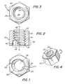
- Fig. 1 eine Unteransicht eines erfindungsgemäßen Innengewinde-Befestigungselements,
- Fig. 2 einen Querschnitt des Befestigungselements nach Fig. 1,
- Fig. 3 eine Draufsicht auf das Befestigungselement nach Fig. 1 und
- Fig. 4 eine perspektivische Ansicht des Befestigungselements nach Fig. 1.
- Bei dem in den Fig. 1 bis 4 dargestellten Innengewinde-Befestigungselement handelt es sich um eine Mutter. Die Erfindung ist jedoch auch bei einem anderen Innengewinde-Befestigungselement anwendbar, das eine an wenigstens einem Ende offene Bohrung mit Innengewinde aufweist.
- Ein Innengewinde-Befestigungselement, z.B. die in den Fig. 1 bis 4 dargestellte Mutter 10, hat einen Körper 20 mit einer Bohrung 22. Die Bohrung 22 Kann den Körper 20 vollständig durchsetzen, wie es bei der dargestellten Mutter der Fall ist, oder sich nur durch einen Teil des Körpers 20 erstrecken. Die Bohrung hat wenigstens ein offenes Ende 24 zur Aufnahme eines Außengewinde-Befestigungselements, z.B. einer Schraube, eines Gewindebolzens oder Gewindestiftes. In wenigstens einem der offenen Enden 24 ist ein Mund 26 vorgesehen, der ein Partialwindungssegment 30 und ein Lippensegment 40 aufweist. Vorzugsweise ist der Mund 26 nicht kreisförmig, wie beispielsweise die weitgehend ovale Form, die in den Fig. 1 und 2 dargestellt ist. Es kann jedoch auch eine kreisrunde Mundform und eine Vielzahl nicht-kreisrunder Mundformen im Zusammenhang mit der vorliegenden Erfindung vorgesehen sein.
- Das Partialwindungssegment 30 des Mundes 26 grenzt an die Bohrung 22 an und ist innen mit einer Partialwindung versehen, deren Gewindeteilung gleich der der Bohrung ist. In dem Partialwindungssegment 30 sind vorzugsweise zwei Partialwindungen vorgesehen. Die erste Partialwindung 32 liegt in der Nähe des offenen Endes der Bohrung 22 und hat eine Umfangslänge, die etwa 15 bis etwa 65 % des Durchmessers der Bohrung 22 beträgt. Die zweite Partialwindung 34 liegt in der Nähe der ersten Partialwindung und hat eine Umfangslänge von etwa 20 bis 70 % des Durchmessers der Bohrung 22. Vorzugsweise hat die erste Partialwindung 32 eine Umfangslänge von etwa 25 bis etwa 40 % des Durchmessers der Bohrung 22 und die zweite Partialwindung 34 eine Umfangslänge von etwa 30 bis etwa 50 % des Durchmessers der Bohrung 22.
- Das Lippensegment 40 ist in dem Mund 26 gegenüber dem Partialwindungssegment 30 ausgebildet. Das Lippensegment 40 ist gewindefrei. Wie Fig. 1 zeigt, hat das Lippensegment 40 vorzugsweise eine gekrümmte Form; es liegen jedoch auch andere Formen im Rahmen der Erfindung, sofern keine Gewinde darin ausgebildet sind.
- Vorzugsweise ist das Lippensegment 40 radial nach außen von der Mittelachse A-A der Bohrung 22 weg geneigt, wie es in Fig. 2 dargestellt ist. Der Neigungswinkel liegt zwischen etwa 2 bis etwa 10° gegenüber der Mittelachse A-A der Bohrung 22, die in Fig. 2 dargestellt ist. Vorzugsweise beträgt der Neigungswinkel etwa 5° gegenüber der Mittelachse A-A der Bohrung 22.
- Das erfindungsgemäße Innengewinde-Befestigungselement kann auf verschiedenste Art hergestellt sein. So kann ein Körper, z.B. eine Mutter, im Guß- oder Extrusionsverfahren auf an sich bekannte Weise geformt werden. Das zur Formung des Körpers verwendete Formwerkzeug oder Gesenk kann so geformt sein, daß das Lippensegment gleichzeitig mit der Formgebung des Körpers geformt wird. Alternativ kann das Lippensegment in dem Mund der Bohrung ausgebildet werden, nachdem der Körper hergestellt worden ist, und zwar durch Anbohren des Körpers an einem gegenüber der Mittelachse der Bohrung versetzten Punkt oder durch Anwendung eines Lochungs- oder Schlagwerkzeugs an diesem Punkt. Die Bohrung kann dann durch Gewindeschneiden mit Gewinde versehen werden. Wo sich das Lippensegment radial nach außen von der Mittelachse der Bohrung weg erstreckt, wird kein Gewinde im Lippensegment ausgebildet. Alternativ kann das Lippensegment durch Bohren oder Lochen ausgebildet werden, nachdem das Gewinde in der Bohrung ausgebildet worden ist.
- Das erfindungsgemäße Innengewinde-Befestigungselement verhindert durch die Ausbildung des gewindefreien Lippensegments 40 eine Gewindeüberkreuzung, da das Lippensegment ein Außengewinde-Befestigungselement beim Einführen in das Innengewinde-Befestigungselement führt und bewirkt, daß das Gewinde des Außengewinde-Befestigungselements neben wenigstens der einen Partialwindung positioniert wird, so daß das Gewinde des Außengewinde-Befestigungs elements mit dem Gewinde des Innengewinde-Befestigungselements in Phase ist. Die Befestigungselemente können dann miteinander verschraubt werden. Die Erfindung bietet daher den Vorteil gegenüber dem Stand der Technik, daß sie ein sehr sorgfältiges Einführen und Ausrichten der Gewinde von Innengewinde- und Außengewinde-Befestigungselement vor deren Verschraubung mittels Maschinenwerkzeugen erübrigt und die Probleme einer Gewindeüberkreuzung, die selbst bei sorgfältigem Zusammenstecken herkömmlicher Befestigungselemente auftreten Können, auf ein Minimum reduziert.
Claims (8)
Applications Claiming Priority (2)
| Application Number | Priority Date | Filing Date | Title |
|---|---|---|---|
| US230589 | 1988-08-10 | ||
| US07/230,589 US4907930A (en) | 1988-08-10 | 1988-08-10 | Anti cross thread nut |
Publications (2)
| Publication Number | Publication Date |
|---|---|
| EP0354446A1 true EP0354446A1 (de) | 1990-02-14 |
| EP0354446B1 EP0354446B1 (de) | 1993-03-10 |
Family
ID=22865793
Family Applications (1)
| Application Number | Title | Priority Date | Filing Date |
|---|---|---|---|
| EP89114175A Expired - Lifetime EP0354446B1 (de) | 1988-08-10 | 1989-08-01 | Innengewinde-Befestigungselement |
Country Status (4)
| Country | Link |
|---|---|
| US (1) | US4907930A (de) |
| EP (1) | EP0354446B1 (de) |
| CA (1) | CA1328751C (de) |
| DE (1) | DE58903705D1 (de) |
Cited By (2)
| Publication number | Priority date | Publication date | Assignee | Title |
|---|---|---|---|---|
| WO2012062728A1 (de) * | 2010-11-08 | 2012-05-18 | Baier & Michels Gmbh & Co. Kg | Gewindeerzeugende mutter, rohteil zur herstellung der mutter und schraubverbindung aus mutter und bolzen |
| WO2021110397A1 (de) * | 2019-12-02 | 2021-06-10 | Ejot Baubefestigungen Gmbh | Buchse mit freigestelltem gewindeabschnitt zur aufnahme eines befestigungselements |
Families Citing this family (16)
| Publication number | Priority date | Publication date | Assignee | Title |
|---|---|---|---|---|
| US5836731A (en) * | 1987-05-20 | 1998-11-17 | Mathread, Inc. | Anti-cross threading fastener |
| JPH0765609B2 (ja) * | 1988-10-19 | 1995-07-19 | 株式会社青山製作所 | 自動調芯用ナット |
| DE9201043U1 (de) * | 1992-01-29 | 1992-03-12 | Emhart Inc., Newark, Del., Us | |
| US5730566A (en) * | 1995-07-21 | 1998-03-24 | Goodwin; Jerry J. | Anti-cross threading fastener |
| AU734031B2 (en) * | 1995-07-21 | 2001-05-31 | Michael A. Garver | Anti-cross threading fastener |
| JPH11509915A (ja) * | 1995-07-21 | 1999-08-31 | ガーバー、マイケル、エイ. | クロスネジ防止ネジ締結装置 |
| ATE241090T1 (de) * | 1999-09-24 | 2003-06-15 | Sugiura Seisakusho Co Ltd | Mutter mit selbstausrichtendem gewinde |
| US6726420B2 (en) | 2000-08-24 | 2004-04-27 | Illinois Tool Works, Inc. | Screw thread with clearance |
| US6561741B2 (en) | 2000-12-19 | 2003-05-13 | Michael A. Garver | Fastener with aligning lead thread |
| US6908272B2 (en) * | 2001-09-28 | 2005-06-21 | Illinois Tool Works Inc. | Threaded fastener nut with anti-cross threading radiused features and tactile feedback features |
| US6702536B2 (en) | 2001-09-28 | 2004-03-09 | Illinois Tool Works Inc. | Threaded fastener nut with anti-cross threading radiused features |
| EP2410191B1 (de) * | 2009-03-16 | 2015-10-21 | Aoyama Seisakusho Co., Ltd. | Buchsenkomponente und befestigungskomponente damit |
| US9433454B2 (en) | 2013-03-14 | 2016-09-06 | Amei Technologies, Inc. | Variable angle screws, plates and systems |
| US9695862B1 (en) | 2015-06-09 | 2017-07-04 | Don K. Clover | Apparatus and method for cleaning a threaded member |
| USD891372S1 (en) * | 2018-09-18 | 2020-07-28 | Cheng Uei Precision Industry Co., Ltd. | Explosion-proof fastening element for lithium battery |
| USD969964S1 (en) | 2020-03-06 | 2022-11-15 | Pentair Residential Filtration, Llc | Filtration system |
Citations (5)
| Publication number | Priority date | Publication date | Assignee | Title |
|---|---|---|---|---|
| NL90717C (de) * | 1900-01-01 | |||
| BE761979A (fr) * | 1971-01-25 | 1971-07-01 | Matthias Spencer & Sons Ltd | Raccords rapides. |
| FR2219699A6 (de) * | 1972-10-25 | 1974-09-20 | Launay Pierre | |
| FR2264215A1 (en) * | 1974-03-14 | 1975-10-10 | Launay Pierre | Cleaning nut for paint covered bolts - has pockets in bore with cutting edges extending axially |
| FR2266558A1 (de) * | 1974-04-05 | 1975-10-31 | Litton Industries Inc |
Family Cites Families (9)
| Publication number | Priority date | Publication date | Assignee | Title |
|---|---|---|---|---|
| US192718A (en) * | 1877-07-03 | Improvement in couplings for lightning-rods | ||
| US561913A (en) * | 1896-06-09 | stoughton | ||
| US341146A (en) * | 1886-05-04 | Feank h | ||
| US1008551A (en) * | 1911-02-23 | 1911-11-14 | William A Lorenz | Coupling. |
| CH188372A (de) * | 1936-07-10 | 1936-12-31 | Fischer Ag Georg | Fitting mit Innengewinde. |
| US2564029A (en) * | 1947-04-11 | 1951-08-14 | Peterson Dana | Nut and bolt construction |
| GB750775A (en) * | 1954-01-28 | 1956-06-20 | Kvernelands Fab As | Means for adjusting rake tines or the like on agricultural implements |
| GB1369594A (en) * | 1970-09-30 | 1974-10-09 | Cambridge Scientific Instr Ltd | Scientific instruments |
| GB2116279A (en) * | 1981-08-20 | 1983-09-21 | Ferranti Ltd | Aligning screw threaded fasteners |
-
1988
- 1988-08-10 US US07/230,589 patent/US4907930A/en not_active Expired - Fee Related
-
1989
- 1989-07-05 CA CA000604856A patent/CA1328751C/en not_active Expired - Fee Related
- 1989-08-01 DE DE8989114175T patent/DE58903705D1/de not_active Expired - Fee Related
- 1989-08-01 EP EP89114175A patent/EP0354446B1/de not_active Expired - Lifetime
Patent Citations (5)
| Publication number | Priority date | Publication date | Assignee | Title |
|---|---|---|---|---|
| NL90717C (de) * | 1900-01-01 | |||
| BE761979A (fr) * | 1971-01-25 | 1971-07-01 | Matthias Spencer & Sons Ltd | Raccords rapides. |
| FR2219699A6 (de) * | 1972-10-25 | 1974-09-20 | Launay Pierre | |
| FR2264215A1 (en) * | 1974-03-14 | 1975-10-10 | Launay Pierre | Cleaning nut for paint covered bolts - has pockets in bore with cutting edges extending axially |
| FR2266558A1 (de) * | 1974-04-05 | 1975-10-31 | Litton Industries Inc |
Cited By (7)
| Publication number | Priority date | Publication date | Assignee | Title |
|---|---|---|---|---|
| WO2012062728A1 (de) * | 2010-11-08 | 2012-05-18 | Baier & Michels Gmbh & Co. Kg | Gewindeerzeugende mutter, rohteil zur herstellung der mutter und schraubverbindung aus mutter und bolzen |
| CN103328834A (zh) * | 2010-11-08 | 2013-09-25 | 拜尔·米歇尔斯有限责任两合公司 | 产生螺纹的螺母、用于制造该螺母的毛坯件及由螺母和螺栓构成的螺纹连接 |
| US8770903B2 (en) | 2010-11-08 | 2014-07-08 | Baier & Michels Gmbh & Co. Kg | Thread-producing nut, blank for the fabrication of said nut, and bolted joint composed of said nut and a bolt |
| RU2572775C2 (ru) * | 2010-11-08 | 2016-01-20 | Байер Унд Михельс Гмбх Унд Ко.Кг | Резьбонарезная гайка, заготовка для изготовления гайки и резьбовое соединение гайки и болта |
| AU2011328261B2 (en) * | 2010-11-08 | 2016-02-11 | Baier & Michels Gmbh & Co. Kg | Thread-producing nut, blank for manufacturing the nut and screwed connection composed of nut and bolt |
| CN103328834B (zh) * | 2010-11-08 | 2016-06-01 | 拜尔·米歇尔斯有限责任两合公司 | 产生螺纹的螺母、用于制造该螺母的毛坯件及由螺母和螺栓构成的螺纹连接 |
| WO2021110397A1 (de) * | 2019-12-02 | 2021-06-10 | Ejot Baubefestigungen Gmbh | Buchse mit freigestelltem gewindeabschnitt zur aufnahme eines befestigungselements |
Also Published As
| Publication number | Publication date |
|---|---|
| CA1328751C (en) | 1994-04-26 |
| EP0354446B1 (de) | 1993-03-10 |
| DE58903705D1 (de) | 1993-04-15 |
| US4907930A (en) | 1990-03-13 |
Similar Documents
| Publication | Publication Date | Title |
|---|---|---|
| EP0354446B1 (de) | Innengewinde-Befestigungselement | |
| EP0381980B1 (de) | Vorrichtung zur Halterung und zum Durchführen von Kabeln, Leitungen, Rohren oder Schläuchen | |
| EP0345373B1 (de) | Schraube | |
| WO2000034671A1 (de) | Schraube, insbesondere betonschraube | |
| EP0102605A1 (de) | Holzschraube | |
| DE4323434C1 (de) | Abscherschraube | |
| EP0939235B1 (de) | Schraube | |
| DE60316873T2 (de) | Löcher zur Entlastung von Spannungen in Verbindungen | |
| EP0576871A1 (de) | Vorrichtung zur Sicherung | |
| DE10302529B4 (de) | Spannsystem für die Werkzeugaufnahme von Werkzeugmaschinen | |
| DE20312075U1 (de) | Vorrichtung mit zwei durch eine Verbindungsschraube zusammengehaltenen Hohlprofilen sowie Werkzeug dazu | |
| DE1961980C3 (de) | Nabenbefestigung | |
| DE19753755C2 (de) | Schlupfarme Schraubverbindung für Stäbe im Bauwesen mit geometrisch definierter Konterung | |
| DE8202339U1 (de) | Schraube | |
| EP0987450B1 (de) | Verbindungseinrichtung zum Verbinden von Profilstäben | |
| DE4307645C2 (de) | Befestigungselement nach Art einer Gewindemutter | |
| DE3116027A1 (de) | Elektrischer steckverbinder | |
| DE7439878U (de) | Befestigungsvorrichtung | |
| DE445509C (de) | Schraubensicherung | |
| DE2141055A1 (de) | Steckbolzenverbindung | |
| DE602004004057T2 (de) | Schraube mit einer Vielzahl von Schraubwinkeln und Walzbacken zu ihrer Herstellung | |
| DE3727400C1 (de) | Fixateur zum Festlegen von Knochenteilen im Koerper | |
| DE3403128A1 (de) | Schraubverbindung | |
| DE19611806C2 (de) | Verbindungsbolzen | |
| DE2215354A1 (de) | Metallische selbsthemmende mehrkant-schraubmutter und verfahren zu deren herstellung |
Legal Events
| Date | Code | Title | Description |
|---|---|---|---|
| PUAI | Public reference made under article 153(3) epc to a published international application that has entered the european phase |
Free format text: ORIGINAL CODE: 0009012 |
|
| AK | Designated contracting states |
Kind code of ref document: A1 Designated state(s): DE ES FR GB IT SE |
|
| 17P | Request for examination filed |
Effective date: 19900725 |
|
| 17Q | First examination report despatched |
Effective date: 19910429 |
|
| GRAA | (expected) grant |
Free format text: ORIGINAL CODE: 0009210 |
|
| AK | Designated contracting states |
Kind code of ref document: B1 Designated state(s): DE ES FR GB IT SE |
|
| PG25 | Lapsed in a contracting state [announced via postgrant information from national office to epo] |
Ref country code: IT Free format text: LAPSE BECAUSE OF FAILURE TO SUBMIT A TRANSLATION OF THE DESCRIPTION OR TO PAY THE FEE WITHIN THE PRE;WARNING: LAPSES OF ITALIAN PATENTS WITH EFFECTIVE DATE BEFORE 2007 MAY HAVE OCCURRED AT ANY TIME BEFORE 2007. THE CORRECT EFFECTIVE DATE MAY BE DIFFERENT FROM THE ONE RECORDED.SCRIBED TIME-LIMIT Effective date: 19930310 Ref country code: FR Effective date: 19930310 Ref country code: GB Effective date: 19930310 Ref country code: ES Free format text: THE PATENT HAS BEEN ANNULLED BY A DECISION OF A NATIONAL AUTHORITY Effective date: 19930310 Ref country code: SE Effective date: 19930310 |
|
| REF | Corresponds to: |
Ref document number: 58903705 Country of ref document: DE Date of ref document: 19930415 |
|
| PGFP | Annual fee paid to national office [announced via postgrant information from national office to epo] |
Ref country code: DE Payment date: 19930713 Year of fee payment: 5 |
|
| EN | Fr: translation not filed | ||
| GBV | Gb: ep patent (uk) treated as always having been void in accordance with gb section 77(7)/1977 [no translation filed] |
Effective date: 19930310 |
|
| PLBE | No opposition filed within time limit |
Free format text: ORIGINAL CODE: 0009261 |
|
| STAA | Information on the status of an ep patent application or granted ep patent |
Free format text: STATUS: NO OPPOSITION FILED WITHIN TIME LIMIT |
|
| 26N | No opposition filed | ||
| PG25 | Lapsed in a contracting state [announced via postgrant information from national office to epo] |
Ref country code: DE Effective date: 19950503 |