EP0353876A1 - Parking brake apparatus - Google Patents
Parking brake apparatus Download PDFInfo
- Publication number
- EP0353876A1 EP0353876A1 EP89306936A EP89306936A EP0353876A1 EP 0353876 A1 EP0353876 A1 EP 0353876A1 EP 89306936 A EP89306936 A EP 89306936A EP 89306936 A EP89306936 A EP 89306936A EP 0353876 A1 EP0353876 A1 EP 0353876A1
- Authority
- EP
- European Patent Office
- Prior art keywords
- manipulation
- actuator
- lever
- parking brake
- force
- Prior art date
- Legal status (The legal status is an assumption and is not a legal conclusion. Google has not performed a legal analysis and makes no representation as to the accuracy of the status listed.)
- Granted
Links
Images


Classifications
-
- B—PERFORMING OPERATIONS; TRANSPORTING
- B60—VEHICLES IN GENERAL
- B60T—VEHICLE BRAKE CONTROL SYSTEMS OR PARTS THEREOF; BRAKE CONTROL SYSTEMS OR PARTS THEREOF, IN GENERAL; ARRANGEMENT OF BRAKING ELEMENTS ON VEHICLES IN GENERAL; PORTABLE DEVICES FOR PREVENTING UNWANTED MOVEMENT OF VEHICLES; VEHICLE MODIFICATIONS TO FACILITATE COOLING OF BRAKES
- B60T7/00—Brake-action initiating means
- B60T7/02—Brake-action initiating means for personal initiation
- B60T7/08—Brake-action initiating means for personal initiation hand actuated
-
- B—PERFORMING OPERATIONS; TRANSPORTING
- B60—VEHICLES IN GENERAL
- B60T—VEHICLE BRAKE CONTROL SYSTEMS OR PARTS THEREOF; BRAKE CONTROL SYSTEMS OR PARTS THEREOF, IN GENERAL; ARRANGEMENT OF BRAKING ELEMENTS ON VEHICLES IN GENERAL; PORTABLE DEVICES FOR PREVENTING UNWANTED MOVEMENT OF VEHICLES; VEHICLE MODIFICATIONS TO FACILITATE COOLING OF BRAKES
- B60T11/00—Transmitting braking action from initiating means to ultimate brake actuator without power assistance or drive or where such assistance or drive is irrelevant
- B60T11/10—Transmitting braking action from initiating means to ultimate brake actuator without power assistance or drive or where such assistance or drive is irrelevant transmitting by fluid means, e.g. hydraulic
- B60T11/103—Transmitting braking action from initiating means to ultimate brake actuator without power assistance or drive or where such assistance or drive is irrelevant transmitting by fluid means, e.g. hydraulic in combination with other control devices
-
- B—PERFORMING OPERATIONS; TRANSPORTING
- B60—VEHICLES IN GENERAL
- B60T—VEHICLE BRAKE CONTROL SYSTEMS OR PARTS THEREOF; BRAKE CONTROL SYSTEMS OR PARTS THEREOF, IN GENERAL; ARRANGEMENT OF BRAKING ELEMENTS ON VEHICLES IN GENERAL; PORTABLE DEVICES FOR PREVENTING UNWANTED MOVEMENT OF VEHICLES; VEHICLE MODIFICATIONS TO FACILITATE COOLING OF BRAKES
- B60T13/00—Transmitting braking action from initiating means to ultimate brake actuator with power assistance or drive; Brake systems incorporating such transmitting means, e.g. air-pressure brake systems
- B60T13/74—Transmitting braking action from initiating means to ultimate brake actuator with power assistance or drive; Brake systems incorporating such transmitting means, e.g. air-pressure brake systems with electrical assistance or drive
- B60T13/746—Transmitting braking action from initiating means to ultimate brake actuator with power assistance or drive; Brake systems incorporating such transmitting means, e.g. air-pressure brake systems with electrical assistance or drive and mechanical transmission of the braking action
-
- B—PERFORMING OPERATIONS; TRANSPORTING
- B60—VEHICLES IN GENERAL
- B60T—VEHICLE BRAKE CONTROL SYSTEMS OR PARTS THEREOF; BRAKE CONTROL SYSTEMS OR PARTS THEREOF, IN GENERAL; ARRANGEMENT OF BRAKING ELEMENTS ON VEHICLES IN GENERAL; PORTABLE DEVICES FOR PREVENTING UNWANTED MOVEMENT OF VEHICLES; VEHICLE MODIFICATIONS TO FACILITATE COOLING OF BRAKES
- B60T7/00—Brake-action initiating means
- B60T7/02—Brake-action initiating means for personal initiation
- B60T7/08—Brake-action initiating means for personal initiation hand actuated
- B60T7/10—Disposition of hand control
- B60T7/107—Disposition of hand control with electrical power assistance
-
- B—PERFORMING OPERATIONS; TRANSPORTING
- B60—VEHICLES IN GENERAL
- B60W—CONJOINT CONTROL OF VEHICLE SUB-UNITS OF DIFFERENT TYPE OR DIFFERENT FUNCTION; CONTROL SYSTEMS SPECIALLY ADAPTED FOR HYBRID VEHICLES; ROAD VEHICLE DRIVE CONTROL SYSTEMS FOR PURPOSES NOT RELATED TO THE CONTROL OF A PARTICULAR SUB-UNIT
- B60W10/00—Conjoint control of vehicle sub-units of different type or different function
- B60W10/04—Conjoint control of vehicle sub-units of different type or different function including control of propulsion units
-
- B—PERFORMING OPERATIONS; TRANSPORTING
- B60—VEHICLES IN GENERAL
- B60W—CONJOINT CONTROL OF VEHICLE SUB-UNITS OF DIFFERENT TYPE OR DIFFERENT FUNCTION; CONTROL SYSTEMS SPECIALLY ADAPTED FOR HYBRID VEHICLES; ROAD VEHICLE DRIVE CONTROL SYSTEMS FOR PURPOSES NOT RELATED TO THE CONTROL OF A PARTICULAR SUB-UNIT
- B60W10/00—Conjoint control of vehicle sub-units of different type or different function
- B60W10/18—Conjoint control of vehicle sub-units of different type or different function including control of braking systems
- B60W10/182—Conjoint control of vehicle sub-units of different type or different function including control of braking systems including control of parking brakes
-
- B—PERFORMING OPERATIONS; TRANSPORTING
- B60—VEHICLES IN GENERAL
- B60W—CONJOINT CONTROL OF VEHICLE SUB-UNITS OF DIFFERENT TYPE OR DIFFERENT FUNCTION; CONTROL SYSTEMS SPECIALLY ADAPTED FOR HYBRID VEHICLES; ROAD VEHICLE DRIVE CONTROL SYSTEMS FOR PURPOSES NOT RELATED TO THE CONTROL OF A PARTICULAR SUB-UNIT
- B60W30/00—Purposes of road vehicle drive control systems not related to the control of a particular sub-unit, e.g. of systems using conjoint control of vehicle sub-units, or advanced driver assistance systems for ensuring comfort, stability and safety or drive control systems for propelling or retarding the vehicle
- B60W30/18—Propelling the vehicle
-
- B—PERFORMING OPERATIONS; TRANSPORTING
- B60—VEHICLES IN GENERAL
- B60W—CONJOINT CONTROL OF VEHICLE SUB-UNITS OF DIFFERENT TYPE OR DIFFERENT FUNCTION; CONTROL SYSTEMS SPECIALLY ADAPTED FOR HYBRID VEHICLES; ROAD VEHICLE DRIVE CONTROL SYSTEMS FOR PURPOSES NOT RELATED TO THE CONTROL OF A PARTICULAR SUB-UNIT
- B60W2540/00—Input parameters relating to occupants
- B60W2540/10—Accelerator pedal position
-
- B—PERFORMING OPERATIONS; TRANSPORTING
- B60—VEHICLES IN GENERAL
- B60W—CONJOINT CONTROL OF VEHICLE SUB-UNITS OF DIFFERENT TYPE OR DIFFERENT FUNCTION; CONTROL SYSTEMS SPECIALLY ADAPTED FOR HYBRID VEHICLES; ROAD VEHICLE DRIVE CONTROL SYSTEMS FOR PURPOSES NOT RELATED TO THE CONTROL OF A PARTICULAR SUB-UNIT
- B60W2710/00—Output or target parameters relating to a particular sub-units
- B60W2710/18—Braking system
- B60W2710/186—Status of parking brakes
-
- B—PERFORMING OPERATIONS; TRANSPORTING
- B60—VEHICLES IN GENERAL
- B60W—CONJOINT CONTROL OF VEHICLE SUB-UNITS OF DIFFERENT TYPE OR DIFFERENT FUNCTION; CONTROL SYSTEMS SPECIALLY ADAPTED FOR HYBRID VEHICLES; ROAD VEHICLE DRIVE CONTROL SYSTEMS FOR PURPOSES NOT RELATED TO THE CONTROL OF A PARTICULAR SUB-UNIT
- B60W30/00—Purposes of road vehicle drive control systems not related to the control of a particular sub-unit, e.g. of systems using conjoint control of vehicle sub-units, or advanced driver assistance systems for ensuring comfort, stability and safety or drive control systems for propelling or retarding the vehicle
- B60W30/18—Propelling the vehicle
- B60W30/18009—Propelling the vehicle related to particular drive situations
- B60W30/18109—Braking
-
- Y—GENERAL TAGGING OF NEW TECHNOLOGICAL DEVELOPMENTS; GENERAL TAGGING OF CROSS-SECTIONAL TECHNOLOGIES SPANNING OVER SEVERAL SECTIONS OF THE IPC; TECHNICAL SUBJECTS COVERED BY FORMER USPC CROSS-REFERENCE ART COLLECTIONS [XRACs] AND DIGESTS
- Y10—TECHNICAL SUBJECTS COVERED BY FORMER USPC
- Y10T—TECHNICAL SUBJECTS COVERED BY FORMER US CLASSIFICATION
- Y10T74/00—Machine element or mechanism
- Y10T74/19—Gearing
- Y10T74/19535—Follow-up mechanism
Definitions
- the present invention relates to a parking brake apparatus having an actuator for reducing the manipulated force of a manipulation lever.
- a conventional parking brake apparatus wherein the actuator thereof is operated by the manipulation of a manipulation switch and the parking brake operated.
- This apparatus has its advantage in that the manipulation of a manipulation lever is not needed and the parking brake is easily operated and released only by the manipulation switch.
- the manipulation of a lever is not needed, the lever manipulation is desirable for some people who are not used to the manipulation switch.
- the lever manipulation is more preferable in the start in sloping roads.
- there are no parking brake apparatuses which are capable of being operated by both a manipulation lever and a manipulation switch.
- Another object is to provide an improved parking brake apparatus which is capable of being operated and released by both a manipulation lever and a manipulation switch.
- a parking brake apparatus comprising: a manipulation lever; an actuator; a balance lever connected at its one end through a first coupling member with the manipulation lever so that a manipulated force of the manipulation lever acts on the one end and at its other end through a second coupling member with the actuator so that an operating force of the actuator acts on the other end, the balance lever having a portion on which a parking brake force acts; relative displacement detecting means for detecting a relative displacement between the manipulation lever and the actuator; and control means for controlling the actuator so that the relative displacement detected by the relative displacement detecting means is reduced.
- the parking brake apparatus may further comprise stop means that is provided in the vicinity of the balance lever and adapted to regulate the balance lever so that the relative displacement becomes less than a fixed value.
- the first and second coupling members may be freely slidable so that the balance lever can be moved only when one of the manipulation lever or the actuator is operated.
- Only one of the first and second coupling members may be freely slidable so that the balance lever can be moved only when one of the manipulation lever or the actuator is operated.
- the parking brake apparatus in a parking brake apparatus which is operated by the manipulation of a parking brake manipulation lever and wherein an actuator is provided to reduce a manipulated force of the parking brake manipulation lever, the parking brake apparatus comprising: a manipulation switch for operating and releasing the actuator without manipulating the manipulation lever; and control means for controlling the operation and release of a parking brake caused by the the actuator on the basis of an output of the manipulation switch.
- the control means may comprise a balance lever having its one end on which the manipulated force of the manipulation lever acts, its other end on which the operating force of the actuator acts and its intermediate portion on which a brake force of the parking brake acts; relative position displacement detecting means for detecting a relative position displacement between the manipulation lever and the actuator; brake force detecting switch for detecting the brake force transmitted to the parking brake; and a control part for controlling the actuator on the basis of the output of the manipulation switch, an output of the relative position displacement detecting means and an output of the brake force detecting switch.
- the control means may further comprise brake manipulation detecting means for detecting a manipulated quantity of a brake pedal, and accelerator manipulation detecting means for detecting a manipulated quantity of an accelerator pedal, and when the manipulation switch is operated with a detection output of the brake manipulation detecting means obtained, the parking brake being operated by the actuator, and when a detection output of the accelerator manipulation is obtained after the operation of the parking brake, the parking brake being released by the actuator.
- a parking brake apparatus in accordance with the present invention.
- a manipulation lever is denoted by 1, an actuator by 2 and a balance lever 3.
- the balance lever 3 is connected at its one end with the manipulation lever 1 so that the manipulated force of the manipulation lever 1 acts on the one end, and at its other end with the actuator 2 so that the operating force of the actuator 2 acts on the other end.
- a parking brake force acts on the intermediate portion of the opposite ends of the balance lever 3.
- the balance lever 3 is connected through a third coupling member 6 with an equalizer 7, which is connected through a bracket member 8 with a brake unit of rear wheels 9 and 10.
- a stop member or stop means 11 is mounted on the third coupling member 6 adjacent the balance member 3, the stop member 11 being adapted to regulate the relative displacement quantity of the balance member 3 less than a fixed value. That is, the stop member 11 regulates the tilt of the balance member 3 less than a fixed value.
- relative displacement detecting switches 12 and 13 On the stop member 11, there is provided a pair of relative displacement detecting switches (relative displacement detecting means) 12 and 13.
- the relative displacement detecting switches 12 and 13 output relative displacement detection signals to a control circuit (control means) 14, respectively.
- the control circuit 14 controls the actuator 2 so that the relative displacement quantity is reduced in response to the relative displacement detection signals of the relative displacement detecting switches 12 and 13.
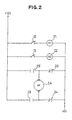
- Fig. 2 illustrates the construction of the control circuit 14 of Fig. 1.
- the aforesaid relative displacement detecting switch is designated by 12 and the aforesaid relative displacement detecting switch by 13.
- 21 denotes a first relay for motor positive rotation that switches when the switch 12 is closed
- 22 denotes a second relay for motor reverse rotation that switches when the switch 13 is closed.
- the balance lever 3 When the manipulation lever 1 is pulled up, the balance lever 3 is tilted and therefore the relative displacement detecting switch 12 is turned on and the first relay 21 is turned on. Since the normally open contact 23 is closed and the normally closed contact 24 is opened by the first relay 21 that has switched, the electric motor 2A rotates in the positive direction. Because of the positive rotation of the electric motor 2A, the balance lever 3 is balanced. This causes the relative displacement detecting switch 12 and also the first relay 21 to be turned off. As a result, the electric motor 2A is stopped. In this manner, the parking brake can be operated by the assist of the actuator 2.
- the electric motor 2A rotates in the reverse direction. Because of the reverse rotation of the electric motor 2A, the balance lever 3 is balanced. This causes the relative displacement detecting switch 13 and also the second relay 22 to be turned off. As a result, the electric motor 2A is stopped. In this manner, the parking brake can be released.
- the actuator 2 is not operated, if the manipulation lever 1 is pulled, the balance lever 3 will be tilted but not tilted more than a fixed value since it is brought into engagement with the stop member 11. Also, since the coupling member 5 is slidable, the parking brake can be operated without a loss of force.
- a sufficient power assist can be obtained. It is noted that a power assist ratio can be changed by providing the coupled portion of the balance lever and coupling member in a position which is shifted toward the side of the manipulation lever or the side of the actuator. Further, since the stop means is provided so that the relative displacement of the manipulation lever and actuator becomes less than a fixed value and also the coupling members between the balance member and the actuator and between the balance member and the manipulation lever are slidable, the balance member is easily moved and the parking brake can be operated without a loss of force even in the case that the actuator is not operated.
- Fig. 3 shows a second embodiment of the present invention that is like that shown in Figs. 1 and 2, except that an assist lever and a brake lever are provided.
- 1′ denotes a manipulation lever, 2′ an actuator, 3′ a balance lever, 12′ a relative displacement detecting switch, 27 a brake lever, 28 an assist lever, and 29 a parking brake.
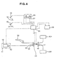
- Figs. 4 through 7 show a third embodiment of the present invention.
- 31 denotes a brake pedal and 32 denotes a brake detecting switch for detecting the manipulation of the brake pedal 31.
- the brake detecting switch 32 inputs its detection signal to a control circuit or control means 33.
- 34 denotes an accelerator pedal and 35 denotes an accelerator detecting switch for detecting the manipulation of the accelerator pedal 34.
- the detection signal of the accelerator detecting switch 35 is inputted to the control circuit 33.
- a battery charger 38 supplies an electric power to the control circuit 33.
- a manipulation lever denoted by 39 applies a parking brake force to a brake unit (not shown) of rear wheels 40A and 40B.
- An actuator denoted by 41 is controlled by the control circuit 33 and has a speed reducer 42 and an electric motor 43. The actuator 41 assists the manipulation lever 39 and also applies the parking brake force to the brake unit by the manipulation of the manipulation switches 36 and 37.
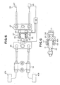
- the manipulated force of the manipulation lever 39 acts on one end of a balance lever 44, and the operating force of the actuator 41 acts on the other end of the balance lever 44.
- the aforesaid parking brake force acts on the intermediate portion of the balance lever 44.
- the balance lever 44 is connected through a coupling mechanism 45 with an equalizer 46.
- the coupling mechanism 45 includes a first coupling member 47 disposed adjacent the balance member 44, a second coupling member 48 disposed adjacent the equalizer 46, a cylindrical member 49 fixed to the first coupling member 47 so as to define a very small interstice between the cylindrical member 49 and a large diameter portion 48A of the second coupling member 48, a spring 50 interposed between the cylindrical member 49 and the large diameter portion 48A of the second coupling member 48, a brake force detecting switch or brake detecting means 51 engaged by the cylindrical member 49 and for detecting a brake force of the degree of creep prevention, and a relative position displacement detecting switches or relative position displacement detecting means 52 and 53 for detecting the relative position displacement between the manipulation lever 39 and the actuator 41.
- the brake force detecting switch 51 detects the brake force by the movement of the cylindrical member 49 caused by the movement of the first coupling member 47.
- the relative position displacement detecting switch 52 detects the relative position displacement between the manipulation lever 39 and the actuator 41 by the tilt of the balance lever 44 caused by the manipulation of the manipulation lever 39, while the other relative position displacement detecting switch 53 detects the relative position displacement between the manipulation lever 39 and the actuator 41 by the tilt of the balance lever 44 caused by the operating force of the actuator 41.
- Each output of the relative position displacement detecting switches 52, 53 and the brake force detecting switch 51 is inputted to the control circuit 33, which controls the actuator 41 on the basis of each output of the relative position displacement detecting switches 52, 53, brake force detecting switch 51, manipulation switches 36, 37, accelerator detecting switch 35 and brake detecting switch 32.
- a bracket member denoted by 54 is adapted to fix the sheath of cables to the vehicle body.
- a normally open contact of an ignition relay is designated by 61, a manipulation switch for operation by 36, a brake detecting switch by 32, a brake force detecting switch by 51 and a first relay for creep prevention by 62.
- 63, 64 and 65 are normally open contacts of the first relay 62, the contact 63 being adapted for self holding the first relay 62, the contact 64 being adapted for actuating a second relay 66 for holding a creep prevention state, and the contact 65 being adapted for actuating a third relay 67 for an electric motor.
- 37 is a manipulation switch for release, 35 an accelerator detecting switch, 68 a normally open contact of the second relay 66, and 69 a normally closed contact of the second rely 66.
- 72 is a fourth relay for an electric motor and 73 a normally open contact 73 of the fourth relay 72, and 74 a normally closed contact of the fourth relay 72.
- An electric motor denoted by 43 constitutes the actuator 41, and a resistance 75 is provided between the battery charger 38 and the normally open contact 73 of the fourth relay 72.
- the electric motor 43 rotates in the positive direction, when the normally open contact 70 is closed and the normally closed contact 71 is opened by the operation of the third relay 67, and rotates in the reverse direction, when the normally open contact 73 is closed and the normally closed contact 70 is opened by the operation of the fourth relay 72.
- the balance lever 34 will be tilted and therefore the relative position displacement detecting switch 52 is closed and the third relay 67 is turned on.
- the electric motor 43 rotates in the positive direction and assists the manipulated force of the manipulation lever 39. Because of the positive rotation of the electric motor 43, the balance lever 34 becomes balanced. This causes the relative position displacement detecting switch 52 to be opened and also the third relay 57 to be turned off. As a result, the electric motor 43 is stopped. In this manner, the parking brake can be operated by both the manipulation lever 39 and the electric motor 43.
- the first relay 62 will be turned on. This causes the normally closed contacts 63, 64 and 65 to be closed, and the first relay 62 is self held and the third relay 67 is turned on. Also, the second relay 66 is turned on, the normally open contact 68 is closed and self held, and the normally closed contact 69 is opened.
- the electric motor 43 rotates in the positive direction.
- the balance lever 44 is tilted, the relative position displacement detecting switch 53 is closed, and since, on the other hand, the brake force detecting switch 51 is opened, the first relay 52 is turned off and the third relay 67 is also turned off.
- the electric motor 43 is consequently stopped.
- the parking brake can be operated by the manipulation of the manipulation switch 36.
- the second relay 66 will be turned off and the normally closed contact 69 that has been opened is closed. Also, since the relative position displacement detecting switch 53 has been closed, the fourth relay 72 is turned on. When the electric motor 43 is rotated in the reverse direction by the operation of the fourth relay 62 and thus the balance lever 44 becomes balanced, the relative position displacement detecting switch 53 is opened, the fourth relay 72 is turned off and therefore the electric motor 43 is stopped. Thus, the parking brake can be released by the manipulation switch 37 for release. It is noted that, if the accelerator pedal 34 is pressed down, the accelerator detecting switch 45 will be opened, and thus the parking brake can be automatically released.
- the parking brake can be operated and released by both the manipulation of the manipulation lever and manipulation switch, and the present invention becomes unexpensive since it employs the common actuator. Also, in the case of the manipulation switch, the parking brake can be automatically released by the manipulation of the accelerator pedal.
Abstract
Description
- The present invention relates to a parking brake apparatus having an actuator for reducing the manipulated force of a manipulation lever.
- There is known a conventional parking brake apparatus wherein the parking brake thereof is operated by a manipulation lever and an actuator is employed to reduce the manipulated force of the manipulation lever. This apparatus has its advantage in that the manipulation lever can be lightly pulled by the power assisted by the actuator. However, in the above conventional parking brake apparatus, a sufficient power assist cannot be obtained because it is difficult to balance the manipulated quantity of the manipulation lever and the operating force of the actuator.
- Also, there is known a conventional parking brake apparatus wherein the actuator thereof is operated by the manipulation of a manipulation switch and the parking brake operated. This apparatus has its advantage in that the manipulation of a manipulation lever is not needed and the parking brake is easily operated and released only by the manipulation switch. Although in this apparatus the manipulation of a lever is not needed, the lever manipulation is desirable for some people who are not used to the manipulation switch. Particularly, in the case of manual transmission vehicles, the lever manipulation is more preferable in the start in sloping roads. However, there are no parking brake apparatuses which are capable of being operated by both a manipulation lever and a manipulation switch.
- Accordingly, it is an object of the present invention to provide an improved parking brake apparatus wherein the relative displacement quantity between the manipulated quantity of a manipulation lever and the operating quantity of an actuator is detected and the relative displacement quantity thus reduced.
- Another object is to provide an improved parking brake apparatus which is capable of being operated and released by both a manipulation lever and a manipulation switch.
- In accordance with one important aspect of the present invention, there is provided a parking brake apparatus comprising: a manipulation lever; an actuator; a balance lever connected at its one end through a first coupling member with the manipulation lever so that a manipulated force of the manipulation lever acts on the one end and at its other end through a second coupling member with the actuator so that an operating force of the actuator acts on the other end, the balance lever having a portion on which a parking brake force acts; relative displacement detecting means for detecting a relative displacement between the manipulation lever and the actuator; and control means for controlling the actuator so that the relative displacement detected by the relative displacement detecting means is reduced.
- The parking brake apparatus may further comprise stop means that is provided in the vicinity of the balance lever and adapted to regulate the balance lever so that the relative displacement becomes less than a fixed value.
- The first and second coupling members may be freely slidable so that the balance lever can be moved only when one of the manipulation lever or the actuator is operated.
- Only one of the first and second coupling members may be freely slidable so that the balance lever can be moved only when one of the manipulation lever or the actuator is operated.
- In accordance with another important aspect of the present invention, in a parking brake apparatus which is operated by the manipulation of a parking brake manipulation lever and wherein an actuator is provided to reduce a manipulated force of the parking brake manipulation lever, the parking brake apparatus comprising: a manipulation switch for operating and releasing the actuator without manipulating the manipulation lever; and control means for controlling the operation and release of a parking brake caused by the the actuator on the basis of an output of the manipulation switch.
- The control means may comprise a balance lever having its one end on which the manipulated force of the manipulation lever acts, its other end on which the operating force of the actuator acts and its intermediate portion on which a brake force of the parking brake acts; relative position displacement detecting means for detecting a relative position displacement between the manipulation lever and the actuator; brake force detecting switch for detecting the brake force transmitted to the parking brake; and a control part for controlling the actuator on the basis of the output of the manipulation switch, an output of the relative position displacement detecting means and an output of the brake force detecting switch.
- The control means may further comprise brake manipulation detecting means for detecting a manipulated quantity of a brake pedal, and accelerator manipulation detecting means for detecting a manipulated quantity of an accelerator pedal, and when the manipulation switch is operated with a detection output of the brake manipulation detecting means obtained, the parking brake being operated by the actuator, and when a detection output of the accelerator manipulation is obtained after the operation of the parking brake, the parking brake being released by the actuator.
- The above and other objects and advantages will become apparent from the following detailed description when read in conjunction with the accompanying drawings wherein:
- FIG. 1 is a schematic plan view showing the overall construction of a first embodiment of the present invention,
- FIG. 2 is a diagram showing the control circuit of FIG. 1,
- FIG. 3 is a schematic view showing a second embodiment of the present invention,
- FIG. 4 is a schematic block diagram showing the overall construction of a third embodiment of the present invention,
- FIG. 5 is an enlarged view showing the control circuit and control mechanism of FIG. 4,
- FIG. 6 is a cross sectional view showing the control mechanism of FIG. 5, and
- FIG. 7 is a diagram showing the control circuit of FIG. 4.
- Referring now in greater detail to the drawings and initially to Figs. 1 and 2, there is shown a preferred embodiment of a parking brake apparatus in accordance with the present invention.
- In Fig. 1, a manipulation lever is denoted by 1, an actuator by 2 and a
balance lever 3. Thebalance lever 3 is connected at its one end with themanipulation lever 1 so that the manipulated force of themanipulation lever 1 acts on the one end, and at its other end with theactuator 2 so that the operating force of theactuator 2 acts on the other end. A parking brake force acts on the intermediate portion of the opposite ends of thebalance lever 3. - 4 denotes a first coupling member of the
manipulation lever 1 and thebalance lever 3, and 5 a second coupling member of theactuator 2 and thebalance lever 3. Thesecoupling members manipulation lever 1 andactuator 2 is operated, the coupling member of themanipulation 1 oractuator 2 that is not operated is slid not so as to disturb the movement of thebalance lever 3. Although in the embodiment of Fig. 1 the twocoupling members balance member 3, it is noted that only theslidable coupling member 5 may also be provided in one end of thebalance member 3 connected with theactuator 2, and the other end may be fixedly connected with themanipulation lever 1. - The
balance lever 3 is connected through a third coupling member 6 with anequalizer 7, which is connected through a bracket member 8 with a brake unit ofrear wheels balance member 3, thestop member 11 being adapted to regulate the relative displacement quantity of thebalance member 3 less than a fixed value. That is, thestop member 11 regulates the tilt of thebalance member 3 less than a fixed value. - On the
stop member 11, there is provided a pair of relative displacement detecting switches (relative displacement detecting means) 12 and 13. The relativedisplacement detecting switches - The
control circuit 14 controls theactuator 2 so that the relative displacement quantity is reduced in response to the relative displacement detection signals of the relativedisplacement detecting switches - Fig. 2 illustrates the construction of the
control circuit 14 of Fig. 1. In Fig. 2, the aforesaid relative displacement detecting switch is designated by 12 and the aforesaid relative displacement detecting switch by 13. 21 denotes a first relay for motor positive rotation that switches when theswitch 12 is closed, and 22 denotes a second relay for motor reverse rotation that switches when theswitch 13 is closed. - 23 denotes a normally open contact of the
first relay 21, 24 a normally closed contact of thefirst relay 21, 25 a normally open contact of thesecond relay 22, and 26 a normally closed contact of thesecond relay 22. - When the normally
open contact 23 is closed and the normally closedcontact 24 is opened by the switching of thefirst relay 21, anelectric motor 2A forming theactuator 2 is rotated in the positive direction. On the other hand, when the normallyopen contact 25 is closed and the normally closedcontact 26 is opened by the switching of thesecond relay 22, theelectric motor 2A is rotated in the reverse direction. - The operation of the embodiment shown in Figs. 1 and 2 will hereinafter be described in detail.
- When the
manipulation lever 1 is pulled up, thebalance lever 3 is tilted and therefore the relativedisplacement detecting switch 12 is turned on and thefirst relay 21 is turned on. Since the normallyopen contact 23 is closed and the normally closedcontact 24 is opened by thefirst relay 21 that has switched, theelectric motor 2A rotates in the positive direction. Because of the positive rotation of theelectric motor 2A, thebalance lever 3 is balanced. This causes the relativedisplacement detecting switch 12 and also thefirst relay 21 to be turned off. As a result, theelectric motor 2A is stopped. In this manner, the parking brake can be operated by the assist of theactuator 2. - Next, when the
manipulation lever 1 is returned to its original position, thebalance lever 3 is tilted in the opposite direction to the above case. The relativedisplacement detecting switch 13 and thesecond relay 22 are consequently turned on. - Since the normally
open contact 25 is closed and the normally closedcontact 26 is opened by thesecond relay 22 that has switched, theelectric motor 2A rotates in the reverse direction. Because of the reverse rotation of theelectric motor 2A, thebalance lever 3 is balanced. This causes the relativedisplacement detecting switch 13 and also thesecond relay 22 to be turned off. As a result, theelectric motor 2A is stopped. In this manner, the parking brake can be released. - It is noted that, in the case that the
actuator 2 is not operated, if themanipulation lever 1 is pulled, thebalance lever 3 will be tilted but not tilted more than a fixed value since it is brought into engagement with thestop member 11. Also, since thecoupling member 5 is slidable, the parking brake can be operated without a loss of force. - As described above, in the present invention, since the actuator is operated so that the relative displacement quantity between the manipulation lever and the actuator can be reduced by detecting the relative displacement, a sufficient power assist can be obtained. It is noted that a power assist ratio can be changed by providing the coupled portion of the balance lever and coupling member in a position which is shifted toward the side of the manipulation lever or the side of the actuator. Further, since the stop means is provided so that the relative displacement of the manipulation lever and actuator becomes less than a fixed value and also the coupling members between the balance member and the actuator and between the balance member and the manipulation lever are slidable, the balance member is easily moved and the parking brake can be operated without a loss of force even in the case that the actuator is not operated.
- Fig. 3 shows a second embodiment of the present invention that is like that shown in Figs. 1 and 2, except that an assist lever and a brake lever are provided. In Fig. 3, 1′ denotes a manipulation lever, 2′ an actuator, 3′ a balance lever, 12′ a relative displacement detecting switch, 27 a brake lever, 28 an assist lever, and 29 a parking brake.
- Figs. 4 through 7 show a third embodiment of the present invention.
- In Fig. 4, 31 denotes a brake pedal and 32 denotes a brake detecting switch for detecting the manipulation of the
brake pedal 31. Thebrake detecting switch 32 inputs its detection signal to a control circuit or control means 33. 34 denotes an accelerator pedal and 35 denotes an accelerator detecting switch for detecting the manipulation of theaccelerator pedal 34. The detection signal of theaccelerator detecting switch 35 is inputted to thecontrol circuit 33. - 36 is a manipulation switch for operation and 37 a manipulation switch for release, each output of these manipulation switches 36 and 37 being inputted to the
control circuit 33. Abattery charger 38 supplies an electric power to thecontrol circuit 33. - A manipulation lever denoted by 39 applies a parking brake force to a brake unit (not shown) of
rear wheels control circuit 33 and has aspeed reducer 42 and anelectric motor 43. Theactuator 41 assists themanipulation lever 39 and also applies the parking brake force to the brake unit by the manipulation of the manipulation switches 36 and 37. - As shown in Fig. 5, the manipulated force of the
manipulation lever 39 acts on one end of abalance lever 44, and the operating force of the actuator 41 acts on the other end of thebalance lever 44. The aforesaid parking brake force acts on the intermediate portion of thebalance lever 44. Thebalance lever 44 is connected through acoupling mechanism 45 with anequalizer 46. Thecoupling mechanism 45 includes afirst coupling member 47 disposed adjacent thebalance member 44, asecond coupling member 48 disposed adjacent theequalizer 46, acylindrical member 49 fixed to thefirst coupling member 47 so as to define a very small interstice between thecylindrical member 49 and alarge diameter portion 48A of thesecond coupling member 48, aspring 50 interposed between thecylindrical member 49 and thelarge diameter portion 48A of thesecond coupling member 48, a brake force detecting switch or brake detecting means 51 engaged by thecylindrical member 49 and for detecting a brake force of the degree of creep prevention, and a relative position displacement detecting switches or relative positiondisplacement detecting means manipulation lever 39 and theactuator 41. - The brake
force detecting switch 51 detects the brake force by the movement of thecylindrical member 49 caused by the movement of thefirst coupling member 47. The relative positiondisplacement detecting switch 52 detects the relative position displacement between themanipulation lever 39 and theactuator 41 by the tilt of thebalance lever 44 caused by the manipulation of themanipulation lever 39, while the other relative positiondisplacement detecting switch 53 detects the relative position displacement between themanipulation lever 39 and theactuator 41 by the tilt of thebalance lever 44 caused by the operating force of theactuator 41. Each output of the relative positiondisplacement detecting switches force detecting switch 51 is inputted to thecontrol circuit 33, which controls theactuator 41 on the basis of each output of the relative positiondisplacement detecting switches force detecting switch 51, manipulation switches 36, 37,accelerator detecting switch 35 andbrake detecting switch 32. A bracket member denoted by 54 is adapted to fix the sheath of cables to the vehicle body. - The
control circuit 33 shown in Fig. 4 will hereinafter be described in conjunction with Fig. 7. In Fig. 7, a normally open contact of an ignition relay is designated by 61, a manipulation switch for operation by 36, a brake detecting switch by 32, a brake force detecting switch by 51 and a first relay for creep prevention by 62. 63, 64 and 65 are normally open contacts of thefirst relay 62, thecontact 63 being adapted for self holding thefirst relay 62, thecontact 64 being adapted for actuating asecond relay 66 for holding a creep prevention state, and thecontact 65 being adapted for actuating athird relay 67 for an electric motor. - 37 is a manipulation switch for release, 35 an accelerator detecting switch, 68 a normally open contact of the
second relay 66, and 69 a normally closed contact of the second rely 66. - 52 is one relative position displacement detecting switch, 53 the other relative position displacement detecting switch, 70 a normally open contact of the
third relay 67 for an electric motor, and 71 a normally closed contact of thethird relay 67. - Also, 72 is a fourth relay for an electric motor and 73 a normally
open contact 73 of thefourth relay 72, and 74 a normally closed contact of thefourth relay 72. An electric motor denoted by 43 constitutes theactuator 41, and aresistance 75 is provided between thebattery charger 38 and the normallyopen contact 73 of thefourth relay 72. Theelectric motor 43 rotates in the positive direction, when the normallyopen contact 70 is closed and the normally closedcontact 71 is opened by the operation of thethird relay 67, and rotates in the reverse direction, when the normallyopen contact 73 is closed and the normally closedcontact 70 is opened by the operation of thefourth relay 72. - The apparatus constructed as shown in Figs. 4 through 7 will hereinafter be described in detail.
- If the
manipulation lever 39 is pulled up, thebalance lever 34 will be tilted and therefore the relative positiondisplacement detecting switch 52 is closed and thethird relay 67 is turned on. When the normallyopen contact 70 is closed and the normally closedcontact 71 is opened by the operation of thethird relay 67, theelectric motor 43 rotates in the positive direction and assists the manipulated force of themanipulation lever 39. Because of the positive rotation of theelectric motor 43, thebalance lever 34 becomes balanced. This causes the relative positiondisplacement detecting switch 52 to be opened and also the third relay 57 to be turned off. As a result, theelectric motor 43 is stopped. In this manner, the parking brake can be operated by both themanipulation lever 39 and theelectric motor 43. - Next, if the
manipulation lever 39 is returned to its original position, thebalance lever 44 will be tilted, the other relative positiondisplacement detecting switch 53 closed and thefourth relay 72 turned on. For this reason, since the normallyopen contact 73 is closed and the normally closed contact 74 is opened, theelectric motor 43 rotates in the reverse direction. Because of the reverse rotation of theelectric motor 43, thebalance lever 44 becomes balanced. This causes the relative positiondisplacement detecting switch 53 to open and also thefourth relay 72 to be turned off. As a result, theelectric motor 43 is stopped. In this manner, the parking brake can be released. - Next, if the
manipulation switch 36 is turned on with both the brakeforce detecting switches first relay 62 will be turned on. This causes the normally closedcontacts first relay 62 is self held and thethird relay 67 is turned on. Also, thesecond relay 66 is turned on, the normallyopen contact 68 is closed and self held, and the normally closedcontact 69 is opened. - Since the normally
open contact 70 is closed and the normally closedcontact 71 is opened by the operation of thethird relay 67, theelectric motor 43 rotates in the positive direction. By the actuation of theelectric motor 43, thebalance lever 44 is tilted, the relative positiondisplacement detecting switch 53 is closed, and since, on the other hand, the brakeforce detecting switch 51 is opened, thefirst relay 52 is turned off and thethird relay 67 is also turned off. Theelectric motor 43 is consequently stopped. Thus, the parking brake can be operated by the manipulation of themanipulation switch 36. - Next, if the
manipulation switch 37 is turned off, thesecond relay 66 will be turned off and the normally closedcontact 69 that has been opened is closed. Also, since the relative positiondisplacement detecting switch 53 has been closed, thefourth relay 72 is turned on. When theelectric motor 43 is rotated in the reverse direction by the operation of thefourth relay 62 and thus thebalance lever 44 becomes balanced, the relative positiondisplacement detecting switch 53 is opened, thefourth relay 72 is turned off and therefore theelectric motor 43 is stopped. Thus, the parking brake can be released by themanipulation switch 37 for release. It is noted that, if theaccelerator pedal 34 is pressed down, theaccelerator detecting switch 45 will be opened, and thus the parking brake can be automatically released. - As described above, according to the present invention, the parking brake can be operated and released by both the manipulation of the manipulation lever and manipulation switch, and the present invention becomes unexpensive since it employs the common actuator. Also, in the case of the manipulation switch, the parking brake can be automatically released by the manipulation of the accelerator pedal.
- While certain representative embodiments and details have been shown for the purpose of illustrating the invention, it will be apparent to those skilled in this art that various changes and modifications may be made therein without departing from the scope of the invention.
Claims (7)
a manipulation lever (1);
an actuator (2);
a balance lever (3) connected at its one end through a first coupling member (4) with said manipulation lever (1) so that a manipulated force of said manipulation lever (1) acts on said one end and at its other end through a second coupling member (5) with said actuator (2) so that an operating force of said actuator (2) acts on said other end, said balance lever (3) having a portion on which a parking brake force acts;
relative displacement detecting means (12, 13) for detecting a relative displacement between said manipulation lever (3) and said actuator (2); and
control means (14) for controlling said actuator (2) so that the relative displacement detected by said relative displacement detecting means (12, 13) is reduced.
a manipulation switch (36, 37) for operating and releasing said actuator (41) without manipulating said manipulation lever (39); and
control means for controlling the operation and release of a parking brake caused by the said actuator (41) on the basis of an output of said manipulation switch (36, 37).
a balance lever (44) having its one end on which the manipulated force of said manipulation lever (39) acts, its other end on which the operating force of said actuator (41) acts and its intermediate portion on which a brake force of said parking brake acts;
relative position displacement detecting means (52, 53) for detecting a relative position displacement between said manipulation lever (39) and said actuator (41);
brake force detecting switch (51) for detecting the brake force transmitted to said parking brake; and
a control part (33) for controlling said actuator (41) on the basis of said output of said manipulation switch (36, 37), an output of said relative position displacement detecting means (52, 53) and an output of said brake force detecting switch (51).
Applications Claiming Priority (4)
| Application Number | Priority Date | Filing Date | Title |
|---|---|---|---|
| JP92744/88 | 1988-07-13 | ||
| JP92743/88 | 1988-07-13 | ||
| JP1988092743U JPH0645404Y2 (en) | 1988-07-13 | 1988-07-13 | Parking brake device |
| JP9274488U JPH062848Y2 (en) | 1988-07-13 | 1988-07-13 | Parking brake device |
Publications (2)
| Publication Number | Publication Date |
|---|---|
| EP0353876A1 true EP0353876A1 (en) | 1990-02-07 |
| EP0353876B1 EP0353876B1 (en) | 1992-12-16 |
Family
ID=26434121
Family Applications (1)
| Application Number | Title | Priority Date | Filing Date |
|---|---|---|---|
| EP89306936A Expired - Lifetime EP0353876B1 (en) | 1988-07-13 | 1989-07-07 | Parking brake apparatus |
Country Status (3)
| Country | Link |
|---|---|
| US (1) | US4991699A (en) |
| EP (1) | EP0353876B1 (en) |
| DE (1) | DE68903901T2 (en) |
Cited By (8)
| Publication number | Priority date | Publication date | Assignee | Title |
|---|---|---|---|---|
| DE4023705A1 (en) * | 1990-07-26 | 1992-01-30 | Teves Gmbh Alfred | ARRANGEMENT FOR HOLDING A VEHICLE ON A SLOPED ROAD |
| DE4129919A1 (en) * | 1991-09-09 | 1993-03-11 | Bayerische Motoren Werke Ag | Electrically operated parking brake esp. for private car - is applied by motor in response to hand lever movement and released with aid of manual device |
| FR2783481A1 (en) * | 1998-09-21 | 2000-03-24 | Renault | Automobile motorized parking brake with possibility of manual operation has drive motor and rack-and-pinion system |
| EP1371537A1 (en) * | 2002-06-10 | 2003-12-17 | CNH Österreich GmbH | Operating device with actuator |
| WO2006100878A1 (en) * | 2005-03-22 | 2006-09-28 | Toyota Jidosha Kabushiki Kaisha | Electric parking brake apparatus |
| WO2007141085A1 (en) * | 2006-06-08 | 2007-12-13 | Siemens Aktiengesellschaft | Method and control arrangement for the controlled release of at least one electric parking brake of a vehicle |
| EP2011705A1 (en) * | 2007-07-02 | 2009-01-07 | Peugeot Citroen Automobiles SA | Method of adjusting a secondary brake |
| CN102328648A (en) * | 2011-07-29 | 2012-01-25 | 中国人民解放军总后勤部军事交通运输研究所 | Trailer braking system combining hydraulic and mechanical braking forms |
Families Citing this family (5)
| Publication number | Priority date | Publication date | Assignee | Title |
|---|---|---|---|---|
| FR2655005B1 (en) * | 1989-11-27 | 1994-04-08 | Andruet Jean Claude | PARKING BRAKE CONTROL DEVICE FOR A MOTOR VEHICLE. |
| US5624352A (en) * | 1995-09-05 | 1997-04-29 | Dura Automotive Systems, Inc. | Ignition-controlled parking brake interlock |
| SE512909C2 (en) * | 1998-10-01 | 2000-06-05 | Volvo Personvagnar Ab | Device for parking brake control lever |
| DE10221740A1 (en) * | 2002-05-16 | 2003-12-04 | Daimler Chrysler Ag | Vehicle brake system with a service brake system and a parking brake system |
| US6848545B2 (en) * | 2002-07-31 | 2005-02-01 | Ventra Group Inc. | Brake actuation assembly for a vehicle |
Citations (5)
| Publication number | Priority date | Publication date | Assignee | Title |
|---|---|---|---|---|
| US1917488A (en) * | 1928-05-12 | 1933-07-11 | Bethenod Joseph | Electric servo-motor for automobiles or the like |
| US1998918A (en) * | 1930-01-16 | 1935-04-23 | Bendix Brake Co | Brake control mechanism |
| US4077487A (en) * | 1976-04-12 | 1978-03-07 | The Raymond Lee Organization, Inc. | Vehicle auxiliary braking system |
| DE3210402A1 (en) * | 1982-03-22 | 1983-09-22 | SWF-Spezialfabrik für Autozubehör Gustav Rau GmbH, 7120 Bietigheim-Bissingen | Brake system, especially for motor vehicles |
| DE3704018A1 (en) * | 1987-02-10 | 1988-08-18 | Porsche Ag | Brake device |
Family Cites Families (10)
| Publication number | Priority date | Publication date | Assignee | Title |
|---|---|---|---|---|
| US1954801A (en) * | 1929-08-26 | 1934-04-17 | Bucyrus Erie Co | Brake |
| GB439923A (en) * | 1934-06-07 | 1935-12-09 | Geoffrey Robert Greenbergh Gat | Improvements in servo brake mechanism for vehicles and the like |
| US2724282A (en) * | 1953-02-12 | 1955-11-22 | Siemens Ag | Reversible torque amplifier with take-off shaft |
| US2763990A (en) * | 1955-03-14 | 1956-09-25 | Mercier Jean | Follow-up system |
| US2922400A (en) * | 1956-04-13 | 1960-01-26 | Hughes Tool Co | Hydraulic servomechanism with feedback-energy-dissipating control valve |
| US2910156A (en) * | 1958-01-22 | 1959-10-27 | Joseph Martin | Power operated emergency brake |
| US3270840A (en) * | 1964-08-12 | 1966-09-06 | Gen Motors Corp | Power operated parking brake having an automatic transmission control gear shift release |
| DE2758644A1 (en) * | 1977-12-29 | 1979-07-05 | Rau Swf Autozubehoer | DEVICE FOR BRAKING MOTOR VEHICLES WITH A BRAKE PEDAL |
| US4561527A (en) * | 1983-01-31 | 1985-12-31 | Mazda Motor Corporation | Electric parking brake system for a vehicle |
| US4629043A (en) * | 1983-01-31 | 1986-12-16 | Mazda Motor Corporation | Electric parking brake system for a vehicle |
-
1989
- 1989-07-06 US US07/376,031 patent/US4991699A/en not_active Expired - Fee Related
- 1989-07-07 EP EP89306936A patent/EP0353876B1/en not_active Expired - Lifetime
- 1989-07-07 DE DE8989306936T patent/DE68903901T2/en not_active Expired - Fee Related
Patent Citations (5)
| Publication number | Priority date | Publication date | Assignee | Title |
|---|---|---|---|---|
| US1917488A (en) * | 1928-05-12 | 1933-07-11 | Bethenod Joseph | Electric servo-motor for automobiles or the like |
| US1998918A (en) * | 1930-01-16 | 1935-04-23 | Bendix Brake Co | Brake control mechanism |
| US4077487A (en) * | 1976-04-12 | 1978-03-07 | The Raymond Lee Organization, Inc. | Vehicle auxiliary braking system |
| DE3210402A1 (en) * | 1982-03-22 | 1983-09-22 | SWF-Spezialfabrik für Autozubehör Gustav Rau GmbH, 7120 Bietigheim-Bissingen | Brake system, especially for motor vehicles |
| DE3704018A1 (en) * | 1987-02-10 | 1988-08-18 | Porsche Ag | Brake device |
Cited By (13)
| Publication number | Priority date | Publication date | Assignee | Title |
|---|---|---|---|---|
| DE4023705A1 (en) * | 1990-07-26 | 1992-01-30 | Teves Gmbh Alfred | ARRANGEMENT FOR HOLDING A VEHICLE ON A SLOPED ROAD |
| DE4129919A1 (en) * | 1991-09-09 | 1993-03-11 | Bayerische Motoren Werke Ag | Electrically operated parking brake esp. for private car - is applied by motor in response to hand lever movement and released with aid of manual device |
| DE4129919C2 (en) * | 1991-09-09 | 2002-05-29 | Bayerische Motoren Werke Ag | Parking brake system for motor vehicles, in particular passenger cars |
| FR2783481A1 (en) * | 1998-09-21 | 2000-03-24 | Renault | Automobile motorized parking brake with possibility of manual operation has drive motor and rack-and-pinion system |
| WO2000017023A1 (en) * | 1998-09-21 | 2000-03-30 | Renault | Power-driven parking brake comprising possible manual actuation |
| EP1371537A1 (en) * | 2002-06-10 | 2003-12-17 | CNH Österreich GmbH | Operating device with actuator |
| WO2006100878A1 (en) * | 2005-03-22 | 2006-09-28 | Toyota Jidosha Kabushiki Kaisha | Electric parking brake apparatus |
| KR100887203B1 (en) * | 2005-03-22 | 2009-03-06 | 도요타 지도샤(주) | Electric parking brake apparatus |
| US7896446B2 (en) | 2005-03-22 | 2011-03-01 | Toyota Jidosha Kabushiki Kaisha | Electric parking brake apparatus |
| WO2007141085A1 (en) * | 2006-06-08 | 2007-12-13 | Siemens Aktiengesellschaft | Method and control arrangement for the controlled release of at least one electric parking brake of a vehicle |
| EP2011705A1 (en) * | 2007-07-02 | 2009-01-07 | Peugeot Citroen Automobiles SA | Method of adjusting a secondary brake |
| FR2918452A1 (en) * | 2007-07-02 | 2009-01-09 | Peugeot Citroen Automobiles Sa | METHOD FOR ADJUSTING A SECONDARY BRAKE |
| CN102328648A (en) * | 2011-07-29 | 2012-01-25 | 中国人民解放军总后勤部军事交通运输研究所 | Trailer braking system combining hydraulic and mechanical braking forms |
Also Published As
| Publication number | Publication date |
|---|---|
| DE68903901D1 (en) | 1993-01-28 |
| US4991699A (en) | 1991-02-12 |
| DE68903901T2 (en) | 1993-07-15 |
| EP0353876B1 (en) | 1992-12-16 |
Similar Documents
| Publication | Publication Date | Title |
|---|---|---|
| US4991699A (en) | Parking brake apparatus | |
| US5178237A (en) | Power-assisted parking brake for vehicles | |
| US6704637B1 (en) | Speed control for a work vehicle | |
| JP2720978B2 (en) | Vehicle operating method and device | |
| US6672281B1 (en) | Mobility enhancement system for electronic throttle controlled vehicles | |
| JPH03239865A (en) | Automatic transmission operating device | |
| JPH0645404Y2 (en) | Parking brake device | |
| JP2001097069A (en) | Drive assisting device | |
| JPH05139269A (en) | Parking brake operating device | |
| JPH062848Y2 (en) | Parking brake device | |
| JP3654979B2 (en) | Electric vehicle | |
| JPH0425407Y2 (en) | ||
| JP3693800B2 (en) | Column shift device | |
| JPH02248762A (en) | Gear control device of vehicle | |
| JPH10164705A (en) | Small motor car | |
| KR100214716B1 (en) | Control system of driving a car | |
| JPH0241072Y2 (en) | ||
| JP3934824B2 (en) | Brake device for vehicle | |
| KR0113825Y1 (en) | Automatic parking brake device through transmission | |
| JP2583684Y2 (en) | Speed change device for automobile | |
| JP2502838Y2 (en) | Parking brake device | |
| JPH045800Y2 (en) | ||
| KR100380612B1 (en) | Push button automatic parking system | |
| JPH09267757A (en) | Steering controller for vehicle | |
| KR0163399B1 (en) | Brake lock device for a handicapped person |
Legal Events
| Date | Code | Title | Description |
|---|---|---|---|
| PUAI | Public reference made under article 153(3) epc to a published international application that has entered the european phase |
Free format text: ORIGINAL CODE: 0009012 |
|
| AK | Designated contracting states |
Kind code of ref document: A1 Designated state(s): DE |
|
| 17P | Request for examination filed |
Effective date: 19900405 |
|
| 17Q | First examination report despatched |
Effective date: 19910507 |
|
| GRAA | (expected) grant |
Free format text: ORIGINAL CODE: 0009210 |
|
| AK | Designated contracting states |
Kind code of ref document: B1 Designated state(s): DE |
|
| REF | Corresponds to: |
Ref document number: 68903901 Country of ref document: DE Date of ref document: 19930128 |
|
| PLBE | No opposition filed within time limit |
Free format text: ORIGINAL CODE: 0009261 |
|
| STAA | Information on the status of an ep patent application or granted ep patent |
Free format text: STATUS: NO OPPOSITION FILED WITHIN TIME LIMIT |
|
| 26N | No opposition filed | ||
| PGFP | Annual fee paid to national office [announced via postgrant information from national office to epo] |
Ref country code: DE Payment date: 19991026 Year of fee payment: 11 |
|
| PG25 | Lapsed in a contracting state [announced via postgrant information from national office to epo] |
Ref country code: DE Free format text: LAPSE BECAUSE OF NON-PAYMENT OF DUE FEES Effective date: 20010501 |