EP0353684A2 - Attachment for hand rails and seats in vehicles - Google Patents
Attachment for hand rails and seats in vehicles Download PDFInfo
- Publication number
- EP0353684A2 EP0353684A2 EP89114089A EP89114089A EP0353684A2 EP 0353684 A2 EP0353684 A2 EP 0353684A2 EP 89114089 A EP89114089 A EP 89114089A EP 89114089 A EP89114089 A EP 89114089A EP 0353684 A2 EP0353684 A2 EP 0353684A2
- Authority
- EP
- European Patent Office
- Prior art keywords
- holding
- seat frame
- contact surface
- vehicles
- clamping piece
- Prior art date
- Legal status (The legal status is an assumption and is not a legal conclusion. Google has not performed a legal analysis and makes no representation as to the accuracy of the status listed.)
- Granted
Links
- 230000000284 resting effect Effects 0.000 claims 1
- 230000015572 biosynthetic process Effects 0.000 description 1
Images
Classifications
-
- B—PERFORMING OPERATIONS; TRANSPORTING
- B61—RAILWAYS
- B61D—BODY DETAILS OR KINDS OF RAILWAY VEHICLES
- B61D33/00—Seats
-
- B—PERFORMING OPERATIONS; TRANSPORTING
- B60—VEHICLES IN GENERAL
- B60N—SEATS SPECIALLY ADAPTED FOR VEHICLES; VEHICLE PASSENGER ACCOMMODATION NOT OTHERWISE PROVIDED FOR
- B60N3/00—Arrangements or adaptations of other passenger fittings, not otherwise provided for
- B60N3/02—Arrangements or adaptations of other passenger fittings, not otherwise provided for of hand grips or straps
- B60N3/026—Arrangements or adaptations of other passenger fittings, not otherwise provided for of hand grips or straps characterised by the fixing means
-
- B—PERFORMING OPERATIONS; TRANSPORTING
- B61—RAILWAYS
- B61D—BODY DETAILS OR KINDS OF RAILWAY VEHICLES
- B61D37/00—Other furniture or furnishings
Definitions
- the invention relates to the fastening of handrails and seat frames in vehicles, in particular rail vehicles, to a stationary part in the passenger compartment (for example floor or side wall).
- Handrails and seat frames are usually attached to a stationary part in the passenger compartment, for example on the floor or the side wall, in particular in rail vehicles for the purpose of transporting passengers, in that the handrail is held in a pot-shaped or flange-shaped base and secured by means of screws in the floor or on the side wall will.
- Seat frames are attached to the floor or the side wall either directly or with the interposition of rails using screws.
- This arrangement and attachment of handrails and seat frames has the disadvantage that threaded holes or through holes with threaded counterparts must be arranged in the floor for fastening the foot of the handrails, the seat frame or the rails of the seat frame.
- the original holes have to be removed in a complex manner and new holes may have to be arranged with a thread. Overall, this fastening method is time-consuming, wage-intensive and therefore uneconomical.
- the object of the present invention was to find a way of fastening handrails and seat frames in vehicles, in particular rail vehicles, which saves time and labor costs and which allows a variable arrangement of the interior of the passenger compartment.
- a holding profile with a contact surface for the holding rod or the seat frame and with a holding cam angled to the contact surface is arranged on the stationary part such that a parallel or inclined to the holding rod or the seat frame Footprint of the stop Profile-extending pressure surface is arranged and that a clampable under the retaining cams clamp piece rests from above on the pressure surface and is fastened with fasteners on the support rod or the seat frame.
- the holding profile which is preferably arranged longitudinally in the passenger compartment, with the contact surface for the holding rod or the seat frame enables the seat arrangement and the arrangement of the holding rods to be designed in a variable manner.
- the arrangement of the contact surface for the support rod and seat frame and holding cams on a common holding profile ensures a precisely fitting connection of the holding rod or the seat frame to the holding profile via the clamping piece.
- the clamping piece is hung under the holding cams and rests from above on the pressure surface of the holding rod or the seat frame and is fastened to the holding rod or the seat frame by means of fastening means, a secure connection of the holding rod or the seat frame to the holding profile is ensured. If the pressure surface of the support rod or the seat frame extends inclined to the contact surface of the holding profile, dimensional tolerances between the contact surface and the pressure surface can be compensated.
- the contact area and the foot of the handrail and the seat frame are profiled on their underside.
- the holding cam is arranged below the contact surface on the holding profile and is provided on its underside with an angle of at least 180 ° to the contact surface. This design and arrangement of the holding cam ensures that the clamping piece can be securely attached to the holding profile.
- the holding cam is rounded on its underside. This rounding ensures that the clamping piece rests securely on the holding cam in any position of the clamping piece if there are differences in height between the holding cam and the pressure surface.
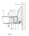
- a holding profile 2 is applied to the floor 1 in the passenger compartment of the rail vehicle by means of conventional fastening means.
- the holding profile 2 is rod-shaped and mounted lengthways in the passenger compartment of the rail vehicle.
- the holding profile 2 has a contact surface 3 on its upper side. This contact area 3 is corrugated or provided with another profile.
- the holding profile 2 is angled on one side and has a holding cam 4 on the angled side, which is provided on its underside with an angle of greater than 180 ° to the contact surface 3.
- the holding cam 4 is rounded on its free lower edge.
- the seat frame 5 of a passenger seat with a foot 6 stands on the contact surface 3 of the holding profile 2.
- the foot 6 of the seat frame 5 is profiled on its underside corresponding to the bearing surface 3.
- the seat frame 5 also has a pressure surface 7 arranged at a distance from the lower end of the foot 6.
- This pressure surface 7 is inclined to the holding cam 4 of the holding profile 2.
- the pressure surface can also be formed parallel to the contact surface 3 of the holding profile 2.
- An approximately C-shaped clamping piece 8 in its vertical cross-section engages with its lower, hook-shaped and congruent end formed under the holding cams 4 under the holding cams 4.
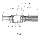
- the upper, also hook-shaped end of the clamping piece 8 lies with pressure cams 9 on the pressure surface 7 of the seat frame 5.
- the clamping piece 8 is fastened to the seat frame 5 by means of screws 10.
- the tightening torque of the screws 10 determines the contact pressure of the seat frame 5 on the bearing surface 3 of the holding profile 2.
- other fastening means for example clips or springs, can also be used.
- About the slope the pressure surface 7, dimensional differences within the holding profile 2 and the foot 6 of the seat frame 5 can be compensated.
- the fastening of a support rod in the passenger compartment to a stationary part, for example the floor or side wall, is carried out in the same way as the fastening of the seat frame 5 in the exemplary embodiment described here.
- the holding profile 2 is embedded in the floor 1.
- the formation and attachment of a support rod or a seat frame 5 is carried out in the same way as in the embodiment described for FIGS. 1 and 2.
- the clamping piece 8 is also identical to the clamping piece 8 of the embodiment described in FIGS. 1 and 2.
Landscapes
- Engineering & Computer Science (AREA)
- Mechanical Engineering (AREA)
- Transportation (AREA)
- Seats For Vehicles (AREA)
- Body Structure For Vehicles (AREA)
- Passenger Equipment (AREA)
- Vehicle Step Arrangements And Article Storage (AREA)
Abstract
Description
Die Erfindung betrifft die Befestigung von Haltestangen und Sitzgestellen in Fahrzeugen, insbesondere Schienenfahrzeugen, an einem ortsfesten Teil im Fahrgastraum (zum Beispiel Fußboden oder Seitenwand).The invention relates to the fastening of handrails and seat frames in vehicles, in particular rail vehicles, to a stationary part in the passenger compartment (for example floor or side wall).
Haltestangen und Sitzgestelle werden insbesondere in Schienenfahrzeugen zum Personentransport üblicherweise an einem ortsfesten Teil im Fahrgastraum, zum Beispiel am Fußboden oder der Seitenwand dadurch befestigt, daß die Haltestange in einen topf- oder bundflanschförmigen Fuß verdrehfest gehaltert und dieser mittels Schrauben im Fußboden oder an der Seitenwand befestigt werden. Sitzgestelle werden entweder direkt oder unter Zwischenschaltung von Schienen ebenfalls mittels Schrauben am Fußboden oder der Seitenwand befestigt. Diese Anordnung und Befestigung von Haltestangen und Sitzgestellen hat den Nachteil, daß zur Befestigung des Fußes der Haltestangen, des Sitzgestelles oder der Schienen des Sitzgestelles im Fußboden Gewindelöcher oder Durchgangslöcher mit Gewindegegenstücken angeordnet werden müssen. Bei Veränderung der Sitzeinteilung oder der Anordnung der Haltestangen müssen die ursprünglichen Löcher auf aufwendige Weise beseitigt und neue Löcher eventuell mit Gewinde angeordnet werden. Insgesamt ist diese Befestigungsmethode zeitaufwendig, lohnintensiv und somit unwirtschaftlich.Handrails and seat frames are usually attached to a stationary part in the passenger compartment, for example on the floor or the side wall, in particular in rail vehicles for the purpose of transporting passengers, in that the handrail is held in a pot-shaped or flange-shaped base and secured by means of screws in the floor or on the side wall will. Seat frames are attached to the floor or the side wall either directly or with the interposition of rails using screws. This arrangement and attachment of handrails and seat frames has the disadvantage that threaded holes or through holes with threaded counterparts must be arranged in the floor for fastening the foot of the handrails, the seat frame or the rails of the seat frame. When changing the seating arrangement or the arrangement of the handrails, the original holes have to be removed in a complex manner and new holes may have to be arranged with a thread. Overall, this fastening method is time-consuming, wage-intensive and therefore uneconomical.
Die Aufgabe vorliegender Erfindung lag darin, zur Befestigung von Haltestangen und Sitzgestellen in Fahrzeugen, insbesondere Schienenfahrzeugen, eine Möglichkeit zu finden, die Zeit und Lohnkosten einspart und die eine variable Anordnung der Inneneinrichtung des Fahrgastraums ermöglicht.The object of the present invention was to find a way of fastening handrails and seat frames in vehicles, in particular rail vehicles, which saves time and labor costs and which allows a variable arrangement of the interior of the passenger compartment.
Diese Aufgabe wird gemäß der Erfindung dadurch gelöst, daß an dem ortsfesten Teil fest ein Halteprofil mit einer Aufstandsfläche für die Haltestange oder das Sitzgestell und mit einem zu der Aufstandsfläche abgewinkelten Haltenocken angeordnet ist, daß an der Haltestange oder dem Sitzgestell eine parallel oder geneigt zu der Aufstandsfläche des Halte profils verlaufende Druckfläche angeordnet ist und daß ein unter den Haltenocken einhängbares Klemmstück von oben auf der Druckfläche anliegt und mit Befestigungsmitteln an der Haltestange oder dem Sitzgestell befestigt ist. Das vorzugsweise längs im Fahrgastraum angeordnete Halteprofil mit der Aufstandsfläche für die Haltestange oder das Sitzgestell ermöglicht eine variable Gestaltung der Sitzanordnung und der Anordnung der Haltestangen. Die Anordnung von Aufstandsfläche für Haltestange und Sitzgestell und Haltenocken an einem gemeinsamen Halteprofil gewährleistet eine passgenaue Verbindung der Haltestange, beziehungsweise des Sitzgestells mit dem Halteprofil über das Klemmstück. Dadurch, daß das Klemmstück unter den Haltenocken eingehängt und von oben auf die Druckfläche der Haltestange, beziehungsweise des Sitzgestells anliegt und mittels Befestigungsmitteln an der Haltestange oder dem Sitzgestell befestigt wird, wird eine sichere Verbindung der Haltestange oder des Sitzgestells mit dem Halteprofil gewährleistet. Bei geneigt zu der Aufstandsfläche des Halteprofils verlaufender Druckfläche der Haltestange oder des Sitzgestells können Maßtoleranzen zwischen Aufstandsfläche und Druckfläche ausgeglichen werden.This object is achieved according to the invention in that a holding profile with a contact surface for the holding rod or the seat frame and with a holding cam angled to the contact surface is arranged on the stationary part such that a parallel or inclined to the holding rod or the seat frame Footprint of the stop Profile-extending pressure surface is arranged and that a clampable under the retaining cams clamp piece rests from above on the pressure surface and is fastened with fasteners on the support rod or the seat frame. The holding profile, which is preferably arranged longitudinally in the passenger compartment, with the contact surface for the holding rod or the seat frame enables the seat arrangement and the arrangement of the holding rods to be designed in a variable manner. The arrangement of the contact surface for the support rod and seat frame and holding cams on a common holding profile ensures a precisely fitting connection of the holding rod or the seat frame to the holding profile via the clamping piece. Characterized in that the clamping piece is hung under the holding cams and rests from above on the pressure surface of the holding rod or the seat frame and is fastened to the holding rod or the seat frame by means of fastening means, a secure connection of the holding rod or the seat frame to the holding profile is ensured. If the pressure surface of the support rod or the seat frame extends inclined to the contact surface of the holding profile, dimensional tolerances between the contact surface and the pressure surface can be compensated.
Zur rutschfesten Verbindung der Haltestange oder des Sitzgestells mit dem Halteprofil sind weiter die Aufstandsfläche und der Fuß der Haltestange und des Sitzgestells auf ihrer Unterseite profiliert.For the non-slip connection of the handrail or the seat frame to the holding profile, the contact area and the foot of the handrail and the seat frame are profiled on their underside.
Der Haltenocken ist unterhalb der Aufstandsfläche an dem Halteprofil angeordnet und auf seiner Unterseite mit einer Abwinklung von mindestens 180° zu der Aufstandsfläche versehen. Durch diese Ausbildung und Anordnung des Haltenockens wird gewährleistet, daß das Klemmstück sicher an dem Halteprofil befestigt werden kann.The holding cam is arranged below the contact surface on the holding profile and is provided on its underside with an angle of at least 180 ° to the contact surface. This design and arrangement of the holding cam ensures that the clamping piece can be securely attached to the holding profile.
Der Haltenocken ist auf seiner Unterseite abgerundet. Durch diese Abrundung wird bei Höhendifferenzen zwischen Haltenocken und Druckfläche ein sicheres Anliegen des Klemmstücks am Haltenocken in jeder Stellung des Klemmstücks gewährleistet.The holding cam is rounded on its underside. This rounding ensures that the clamping piece rests securely on the holding cam in any position of the clamping piece if there are differences in height between the holding cam and the pressure surface.
Einzelheiten der Erfindung werden anhand von Ausführungsbeispielen in der Zeichnung erläutert.Details of the invention are explained using exemplary embodiments in the drawing.
Es zeigen
- Fig. 1 einen vertikalen Querschnitt durch eine Befestigung gemäß der Erfindung,
- Fig. 2 den Schnitt nach Linie II-II der Fig. 1,
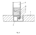
- Fig. 3 ein zweites Ausführungsbeispiel der Befestigung gemäß der Erfindung im vertikalen Querschnitt.
- 1 is a vertical cross section through an attachment according to the invention,
- 2 shows the section along line II-II of FIG. 1,
- Fig. 3 shows a second embodiment of the fastening according to the invention in vertical cross section.
Bei dem in den Fig. 1 und 2 dargestellten Ausführungsbeispiel der Erfindung ist auf den Fußboden 1 im Fahrgastraum des Schienenfahrzeugs ein Halteprofil 2 mittels üblicher Befestigungsmittel aufgebracht. Das Halteprofil 2 ist dabei stabförmig ausgebildet und im Fahrgastraum des Schienenfahrzeugs längs angebracht. Auf seiner Oberseite weist das Halteprofil 2 eine Aufstandsfläche 3 auf. Diese Aufstandsfläche 3 ist geriffelt oder mit einer sonstigen Profilierung versehen. Das Halteprofil 2 ist einseitig abgewinkelt und weist an der abgewinkelten Seite einen Haltenocken 4 auf, der auf seiner Unterseite mit einer Abwinklung von größer als 180° zu der Aufstandsfläche 3 versehen ist. Der Haltenocken 4 ist dabei an seiner freien unteren Kante abgerundet. Auf der Aufstandsfläche 3 des Halteprofils 2 steht das Sitzgestell 5 eines Fahrgastsitzes mit einem Fuß 6 auf. Der Fuß 6 des Sitzgestells 5 ist dabei auf seiner Unterseite entsprechend der Auflagefläche 3 profiliert. Das Sitzgestell 5 weist weiter eine mit Abstand zu dem unteren Ende des Fußes 6 angeordnete Druckfläche 7 auf. Diese Druckfläche 7 ist mit Neigung zu dem Haltenocken 4 des Halteprofils 2 versehen. Gemäß einem anderen, nicht dargestellten Ausführungsbeispiel der Erfindung kann die Druckfläche jedoch auch parallel zu der Aufstandsfläche 3 des Halteprofils 2 ausgebildet sein. Ein in seinem vertikalen Querschnitt etwa C-förmig ausgebildetes Klemmstück 8 greift mit seinem unteren, hakenförmigen und deckungsgleich zu der Unterseite des Haltenockens 4 ausgebildeten Ende unter den Haltenocken 4. Das obere, ebenfalls hakenförmig ausgebildete Ende des Klemmstücks 8 liegt mit Drucknocken 9 auf der Druckfläche 7 des Sitzgestells 5 an. Das Klemmstück 8 ist dabei mittels Schrauben 10 an dem Sitzgestell 5 befestigt. Das Anzugsmoment der Schrauben 10 bestimmt die Anpreßkraft des Sitzgestells 5 auf die Auflagefläche 3 des Halteprofils 2. Es können jedoch auch andere Befestigungsmittel, beispielsweise Klammern oder Federn, verwendet werden. Über die Neigung der Druckfläche 7 können Maßdifferenzen innerhalb des Halteprofils 2 und des Fußes 6 des Sitzgestells 5 ausgeglichen werden.In the embodiment of the invention shown in FIGS. 1 and 2, a
Die Befestigung einer Haltestange im Fahrgastraum an einem ortsfesten Teil, zum Beispiel Fußboden oder Seitenwand erfolgt auf gleiche Weise wie die Befestigung des Sitzgestells 5 in vorliegend beschriebenem Ausführungsbeispiel.The fastening of a support rod in the passenger compartment to a stationary part, for example the floor or side wall, is carried out in the same way as the fastening of the
Bei dem in der Fig. 3 dargestellten Ausführungsbeispiel der Erfindung ist das Halteprofil 2 in den Fußboden 1 eingelassen. Die Ausbildung und Befestigung einer Haltestange oder eines Sitzgestells 5 erfolgt auf gleiche Weise wie in dem zu den Fig. 1 und 2 beschriebenen Ausführungsbeispiel. Das Klemmstück 8 ist ebenfalls identisch mit dem Klemmstück 8 der in den Fig.1 und 2 beschriebenen Ausführung.In the embodiment of the invention shown in FIG. 3, the
Claims (6)
Priority Applications (1)
| Application Number | Priority Date | Filing Date | Title |
|---|---|---|---|
| AT89114089T ATE95768T1 (en) | 1988-08-04 | 1989-07-31 | ATTACHMENT OF HANDLEBARS AND SEAT FRAMES IN VEHICLES. |
Applications Claiming Priority (2)
| Application Number | Priority Date | Filing Date | Title |
|---|---|---|---|
| DE3826470 | 1988-08-04 | ||
| DE3826470A DE3826470A1 (en) | 1988-08-04 | 1988-08-04 | ATTACHMENT OF HANDLEBARS AND SEAT RACKS IN VEHICLES |
Publications (3)
| Publication Number | Publication Date |
|---|---|
| EP0353684A2 true EP0353684A2 (en) | 1990-02-07 |
| EP0353684A3 EP0353684A3 (en) | 1990-07-11 |
| EP0353684B1 EP0353684B1 (en) | 1993-10-13 |
Family
ID=6360215
Family Applications (1)
| Application Number | Title | Priority Date | Filing Date |
|---|---|---|---|
| EP89114089A Expired - Lifetime EP0353684B1 (en) | 1988-08-04 | 1989-07-31 | Attachment for hand rails and seats in vehicles |
Country Status (3)
| Country | Link |
|---|---|
| EP (1) | EP0353684B1 (en) |
| AT (1) | ATE95768T1 (en) |
| DE (2) | DE3826470A1 (en) |
Cited By (4)
| Publication number | Priority date | Publication date | Assignee | Title |
|---|---|---|---|---|
| EP1304253A2 (en) * | 2001-10-18 | 2003-04-23 | Vogelsitze GmbH | Device for fastening a passenger seat |
| EP1304254A3 (en) * | 2001-10-18 | 2004-01-28 | Vogelsitze GmbH | Device for fastening a passenger seat |
| EP3933214A1 (en) * | 2020-07-01 | 2022-01-05 | Bombardier Transportation GmbH | Seat attachment system for a mass transit vehicle |
| EP3539818B1 (en) | 2018-03-14 | 2022-11-30 | Aguti Produktentwicklung & Design GmbH | Belt frame for a vehicle seat or a bench seat and vehicle seating assembly |
Citations (3)
| Publication number | Priority date | Publication date | Assignee | Title |
|---|---|---|---|---|
| US2589922A (en) * | 1949-03-01 | 1952-03-18 | Harry A Bowman | Quick detachable anchoring means for chairs and the like |
| DE2349828A1 (en) * | 1973-10-04 | 1975-04-24 | Daimler Benz Ag | Box shaped vehicle seat foot - has housing with an opening at its bottom covered by a plastic plate |
| DE2719455A1 (en) * | 1977-04-30 | 1978-11-02 | Magirus Deutz Ag | Adjustable mounting for bus seat - has profiled rail housed in recess at side of gangway to clamp fitting on inside of legs |
-
1988
- 1988-08-04 DE DE3826470A patent/DE3826470A1/en not_active Withdrawn
-
1989
- 1989-07-31 EP EP89114089A patent/EP0353684B1/en not_active Expired - Lifetime
- 1989-07-31 DE DE89114089T patent/DE58905893D1/en not_active Expired - Fee Related
- 1989-07-31 AT AT89114089T patent/ATE95768T1/en not_active IP Right Cessation
Patent Citations (3)
| Publication number | Priority date | Publication date | Assignee | Title |
|---|---|---|---|---|
| US2589922A (en) * | 1949-03-01 | 1952-03-18 | Harry A Bowman | Quick detachable anchoring means for chairs and the like |
| DE2349828A1 (en) * | 1973-10-04 | 1975-04-24 | Daimler Benz Ag | Box shaped vehicle seat foot - has housing with an opening at its bottom covered by a plastic plate |
| DE2719455A1 (en) * | 1977-04-30 | 1978-11-02 | Magirus Deutz Ag | Adjustable mounting for bus seat - has profiled rail housed in recess at side of gangway to clamp fitting on inside of legs |
Cited By (8)
| Publication number | Priority date | Publication date | Assignee | Title |
|---|---|---|---|---|
| EP1304253A2 (en) * | 2001-10-18 | 2003-04-23 | Vogelsitze GmbH | Device for fastening a passenger seat |
| EP1304253A3 (en) * | 2001-10-18 | 2004-01-28 | Vogelsitze GmbH | Device for fastening a passenger seat |
| EP1304254A3 (en) * | 2001-10-18 | 2004-01-28 | Vogelsitze GmbH | Device for fastening a passenger seat |
| EP3539818B1 (en) | 2018-03-14 | 2022-11-30 | Aguti Produktentwicklung & Design GmbH | Belt frame for a vehicle seat or a bench seat and vehicle seating assembly |
| EP3933214A1 (en) * | 2020-07-01 | 2022-01-05 | Bombardier Transportation GmbH | Seat attachment system for a mass transit vehicle |
| US20220001771A1 (en) * | 2020-07-01 | 2022-01-06 | Bombardier Transportation Gmbh | Seat Attachment System for a Mass Transit Vehicle |
| CN113978323A (en) * | 2020-07-01 | 2022-01-28 | 庞巴迪运输有限公司 | Seat attachment system for mass transit vehicles |
| US11642984B2 (en) * | 2020-07-01 | 2023-05-09 | Bombardier Transportation Gmbh | Seat attachment system for a mass transit vehicle |
Also Published As
| Publication number | Publication date |
|---|---|
| EP0353684B1 (en) | 1993-10-13 |
| DE58905893D1 (en) | 1993-11-18 |
| EP0353684A3 (en) | 1990-07-11 |
| ATE95768T1 (en) | 1993-10-15 |
| DE3826470A1 (en) | 1990-02-08 |
Similar Documents
| Publication | Publication Date | Title |
|---|---|---|
| DE68919181T2 (en) | Backrest attachment. | |
| DE68908657T2 (en) | Fastening structure of a roof panel. | |
| DE29509049U1 (en) | Device for clamping components, in particular sheet metal, in the course of a welding or assembly line | |
| EP0626294A1 (en) | Roof carrier for vehicles | |
| EP0353684B1 (en) | Attachment for hand rails and seats in vehicles | |
| DE9213169U1 (en) | Screw connection for adjustable fastening of a device or a device carrier to a base | |
| DE3201171A1 (en) | Attachment of luggage brackets, railings or the like on a motor vehicle roof | |
| DE20117398U1 (en) | Holder for solar modules | |
| DE19740820A1 (en) | Vehicle roof rack with cross-rails and rack feet | |
| DE2719455A1 (en) | Adjustable mounting for bus seat - has profiled rail housed in recess at side of gangway to clamp fitting on inside of legs | |
| DE4128114C2 (en) | ||
| DE3611136A1 (en) | Clamping securing means | |
| EP0787880A1 (en) | Height adjusting device for a lower finishing part of doors or windows | |
| EP0806321A3 (en) | Roof rails for vehicles | |
| DE19528212A1 (en) | Vehicle roof rack for transporting items - comprises two side rails fixed to roof and has each end zone of cross bearer moulded into support foot with grip | |
| DE4007263A1 (en) | Roof-rack mounting into recessed grooves - has grip fitting inside groove and with adjustable grip feet on roof-rack | |
| DE10224095A1 (en) | Soft top fastening for a convertible | |
| DE3625785A1 (en) | Car roof-rack for a car roof which does not have a drip moulding | |
| DE29916152U1 (en) | Luggage carriers for the tailgate of motor vehicles | |
| DE102012012490B4 (en) | Mounting arrangement | |
| DE3120616A1 (en) | Liftgate for lorries or the like | |
| DE3819816A1 (en) | Covering profile for an awning | |
| DE3604772A1 (en) | Roof rack for a motor vehicle, especially a car | |
| DE3518689C2 (en) | Support leg for a roof rack on a passenger car | |
| DE102022110610A1 (en) | Recreational vehicle, especially motor home, and seatbelt assembly |
Legal Events
| Date | Code | Title | Description |
|---|---|---|---|
| PUAI | Public reference made under article 153(3) epc to a published international application that has entered the european phase |
Free format text: ORIGINAL CODE: 0009012 |
|
| 17P | Request for examination filed |
Effective date: 19890816 |
|
| AK | Designated contracting states |
Kind code of ref document: A2 Designated state(s): AT CH DE FR IT LI |
|
| PUAL | Search report despatched |
Free format text: ORIGINAL CODE: 0009013 |
|
| AK | Designated contracting states |
Kind code of ref document: A3 Designated state(s): AT CH DE FR IT LI |
|
| 17Q | First examination report despatched |
Effective date: 19920207 |
|
| RAP1 | Party data changed (applicant data changed or rights of an application transferred) |
Owner name: ABB HENSCHEL WAGGON UNION GMBH |
|
| GRAA | (expected) grant |
Free format text: ORIGINAL CODE: 0009210 |
|
| AK | Designated contracting states |
Kind code of ref document: B1 Designated state(s): AT CH DE FR IT LI |
|
| REF | Corresponds to: |
Ref document number: 95768 Country of ref document: AT Date of ref document: 19931015 Kind code of ref document: T |
|
| REF | Corresponds to: |
Ref document number: 58905893 Country of ref document: DE Date of ref document: 19931118 |
|
| ET | Fr: translation filed | ||
| ITF | It: translation for a ep patent filed | ||
| PGFP | Annual fee paid to national office [announced via postgrant information from national office to epo] |
Ref country code: CH Payment date: 19940711 Year of fee payment: 6 |
|
| PGFP | Annual fee paid to national office [announced via postgrant information from national office to epo] |
Ref country code: FR Payment date: 19940712 Year of fee payment: 6 |
|
| PGFP | Annual fee paid to national office [announced via postgrant information from national office to epo] |
Ref country code: AT Payment date: 19940713 Year of fee payment: 6 |
|
| PLBE | No opposition filed within time limit |
Free format text: ORIGINAL CODE: 0009261 |
|
| STAA | Information on the status of an ep patent application or granted ep patent |
Free format text: STATUS: NO OPPOSITION FILED WITHIN TIME LIMIT |
|
| PGFP | Annual fee paid to national office [announced via postgrant information from national office to epo] |
Ref country code: DE Payment date: 19940816 Year of fee payment: 6 |
|
| 26N | No opposition filed | ||
| PG25 | Lapsed in a contracting state [announced via postgrant information from national office to epo] |
Ref country code: LI Effective date: 19950731 Ref country code: CH Effective date: 19950731 Ref country code: AT Effective date: 19950731 |
|
| REG | Reference to a national code |
Ref country code: CH Ref legal event code: PL |
|
| PG25 | Lapsed in a contracting state [announced via postgrant information from national office to epo] |
Ref country code: DE Effective date: 19960402 |
|
| PG25 | Lapsed in a contracting state [announced via postgrant information from national office to epo] |
Ref country code: FR Effective date: 19960430 |
|
| REG | Reference to a national code |
Ref country code: FR Ref legal event code: ST |
|
| REG | Reference to a national code |
Ref country code: FR Ref legal event code: ST |
|
| REG | Reference to a national code |
Ref country code: FR Ref legal event code: ST |
|
| PG25 | Lapsed in a contracting state [announced via postgrant information from national office to epo] |
Ref country code: IT Free format text: LAPSE BECAUSE OF NON-PAYMENT OF DUE FEES;WARNING: LAPSES OF ITALIAN PATENTS WITH EFFECTIVE DATE BEFORE 2007 MAY HAVE OCCURRED AT ANY TIME BEFORE 2007. THE CORRECT EFFECTIVE DATE MAY BE DIFFERENT FROM THE ONE RECORDED. Effective date: 20050731 |