EP0353365A2 - Ultrasonic cell-destroyer - Google Patents
Ultrasonic cell-destroyer Download PDFInfo
- Publication number
- EP0353365A2 EP0353365A2 EP88308544A EP88308544A EP0353365A2 EP 0353365 A2 EP0353365 A2 EP 0353365A2 EP 88308544 A EP88308544 A EP 88308544A EP 88308544 A EP88308544 A EP 88308544A EP 0353365 A2 EP0353365 A2 EP 0353365A2
- Authority
- EP
- European Patent Office
- Prior art keywords
- container
- ultrasonic
- cells
- containers
- destroyer
- Prior art date
- Legal status (The legal status is an assumption and is not a legal conclusion. Google has not performed a legal analysis and makes no representation as to the accuracy of the status listed.)
- Granted
Links
Images


Classifications
-
- C—CHEMISTRY; METALLURGY
- C12—BIOCHEMISTRY; BEER; SPIRITS; WINE; VINEGAR; MICROBIOLOGY; ENZYMOLOGY; MUTATION OR GENETIC ENGINEERING
- C12N—MICROORGANISMS OR ENZYMES; COMPOSITIONS THEREOF; PROPAGATING, PRESERVING, OR MAINTAINING MICROORGANISMS; MUTATION OR GENETIC ENGINEERING; CULTURE MEDIA
- C12N1/00—Microorganisms, e.g. protozoa; Compositions thereof; Processes of propagating, maintaining or preserving microorganisms or compositions thereof; Processes of preparing or isolating a composition containing a microorganism; Culture media therefor
- C12N1/06—Lysis of microorganisms
- C12N1/066—Lysis of microorganisms by physical methods
-
- C—CHEMISTRY; METALLURGY
- C12—BIOCHEMISTRY; BEER; SPIRITS; WINE; VINEGAR; MICROBIOLOGY; ENZYMOLOGY; MUTATION OR GENETIC ENGINEERING
- C12M—APPARATUS FOR ENZYMOLOGY OR MICROBIOLOGY; APPARATUS FOR CULTURING MICROORGANISMS FOR PRODUCING BIOMASS, FOR GROWING CELLS OR FOR OBTAINING FERMENTATION OR METABOLIC PRODUCTS, i.e. BIOREACTORS OR FERMENTERS
- C12M47/00—Means for after-treatment of the produced biomass or of the fermentation or metabolic products, e.g. storage of biomass
- C12M47/06—Hydrolysis; Cell lysis; Extraction of intracellular or cell wall material
Abstract
Description
- The present invention relates to an ultrasonic cell-destroyer, and particularly to an apparatus for destroying cells floating in a solution in a closed container by radiating ultrasonic waves to the solution in the container, thereby subjecting the floating cells to impacts and/or cavitations caused by the radiation of ultrasonic waves and destroying them.
- Recently in medical science, agricultural and horitcultural chemistry and other science fields biochemical analysis has been popular, and accordingly there is an ever increasing demand for destruction of cells. In general, destruction of cells means that the outer membrane of each cell is broken to remove its minute organs or organelles.
- Sometimes, destruction of cells means that the organelles of the cell are destroyed. An ultrasonic cell-destroyer has been used for this purpose. In a conventional ultrasonic cell-destroyer an ultrasonic generator horn or tip is soaked in the cell-suspended solution in an open container, such as a test glass or test cup. Then, the vibrator of the ultrasonic generator is vibrated by an associated high-frequency oscillator, thereby subjecting the cells to the radiation of the ultrasonic wave in the solution so that their membranes may be broken by force caused by cavitation.
- Advantageously in this conventional ultrasonic cell-destroyer, a lot of similar cells can be destroyed, but it has the following defects: it cannot destroy cells of different kinds simultaneously. The container must be open so that an ultrasonic horn may be put in the container, and therefore there is a danger of scattering of aerosol from the open mouth of the container. This is most dangerous to persons handling virus and other infectious agents. Also, there is a danger of contamination of cells with bacteria. Sometimes water leaks, and the PH value varies.
- In an attempt to solve these problems there has been proposed an ultrasonic cell-destroyer as shown in Figs. 9 and 10. It is shown as comprising a plurality of closed
containers 1′, each containing a given quantity of solution in which cells to be destroyed are suspended, and anelongated metal rod 2′, and avessel 3′ containing a quantity of liquid W and being equipped with an ultrasonic generator (not shown) at its bottom. As shown, thecontainers 1′ are partly soaked in the bath of thevessel 3′. In operation themetal rods 2′ are subjected to the ultrasonic wave, and therods 2′are resonant with the ultrasonic sound to break the membranes of the cells and remove their organelles. - This ultrasonic cell-destroyer permits destruction of a relatively small quantity of cells of different kinds at one time. The containers are closed, and therefore there is no danager of scattering of aerosol, and there is neither leakage of water nor variation of PH value. Still advantageously, no physical factors will vary with time and temperature. It, however, has the following defects:
- 1. A very small quantity of cell sample, for instance ranging from 50 to 250 microliters, cannot be subjected to ultrasonic destruction because the use of a metal rod of substantial size prevents the size of the container from being reduced to the extent that cells may be exposed to the vibration caused by the metal rod in the container.
- 2. The presence of the metal rod in the container makes it difficult to subject the solution in the container to centrifugal separation.
- According to the present invention there is provided an ultrasonic cell-destroyer comprising at least one closed container comprising a container body and a closure for containing a given quantity of liquid in which cells to be destroyed are suspended, and a vessel equipped with ultrasonic wave generator means at its bottom so as to destroy cells in the container, hich is partly soaked in the bath of the vessel, characterised in that the container body has an upward converging or concave groove on its bottom end.
- The container body may have a tapering shape converging towards its bottom end. The bottom end on which a groove is formed, may have a semispherical shape.
- In order to permit the simultaneous destruction of the cells contained in a plurality of containers the apparatus may comprise a rotatable disk having the plurality of apertures in which the containers are to be fitted, the disk being laid above the surface of the bath in the vessel, and means for rotating the disk slowly, thereby permitting the containers to travel circular paths while being exposed to the radiation of ultrasonic wave in the bath. Said means for rotating the disk slowly may be an electric motor, otherwise, it may be a manually operated device. The disk may comprise circular floor and ceiling plates and a circumferential wall integrally connected to the floor plate. The floor plate has a plurality of apertures in which the containers are to be fitted, and the ceiling plate is used as a closure to define a closed space along with the floor plate and the circumferential wall. Then, the clearance between the ceiling and the top surface of the closure of the container provides a space which permits efficient generation of resonance from ultrasonic energy in the container, thereby making full use of the ultrasonic energy to destroy the cells in the container.
- In use a small quantity of solution in which cells are suspended, is put in each container, and then it is closed with its closure. A plurality of closed containers are partly soaked in the bath in the vessel so that the level of solution in each container may be lower than the surface of the bath. Then, the ultrasonic generator means is operated to radiate ultrasonic waves to the bath. It is supposed that the destruction of cells in the containers is caused by:
- 1. Each closed container has a resonant vibration at its intrinsic or natural frequency, thereby causing the secondary vibration in the solution in the container. Thus, cavitation is caused in the solution to destroy the cells and remove their organelles.
- 2. When each closed container is exposed to ultrasonic waves, it vibrates vigorously, and accordingly the cells are repeatedly struck against the inner surface of the container. Thus, the cells are destroyed, and their organelles are removed.
- Each container has an upward converging or concave groove at its bottom, and the ultrasonic energy is apt to converge to the reentrant portion of the bottom of the container. The solution in which cells to be destroyed are suspended, are put in the bottom portion of the container, and therefore effective destruction can be performed. The rod-free container is useful in destroying a very small amount of cell in the solution, and it facilitates subsequent centrifugal separation. In case of fitting a plurality of containers in the apertures of a rotary disk, cells suspended in the solutions in these containers can be equally destroyed.
- Some embodiments of the present invention will now be described by way of example and with reference to the accompanying drawings, in which:-
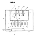
- Fig. 1 is a longitudinal sectional view of an ultrasonic cell-destroyer according to a first embodiment,
- Fig. 2 is a longitudinal sectional view of a closed container,
- Fig. 3 is an enlarged longitudinal sectional view of the bottom part of the closed container of Fig. 2,
- Fig. 4 is a longitudinal view of another example of a closed container,
- Fig. 5 is a longitudinal sectional view of an ultrasonic cell-destroyer according to a second embodiment,
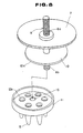
- Fig. 6 is a plan view of the ultrasonic cell-destroyer of Fig. 5,
- Fig. 7 is a longitudinal sectional view of the part of the apparatus of Fig. 5 at which a container is mounted,
- Fig. 8 is a perspective view of part of the apparatus of Fig. 5, showing how a holder rod is fitted in an associated disk.
- Fig. 9 is a longitudinal sectional view of a conventional closed container; and
- Fig. 10 is a longitudinal sectional view of a conventional ultrasonic cell-destroyer with a closed container mounted.
- Referring to Fig.s 1 to 4, there is shown an ultrasonic cell-destroyer according to a first embodiment of the present invention.
- The cell-destroyer comprises, in a
casing 5, a high-frequency oscillator 1, vibratingelements 2 such as ferrite magnetostriction vibrating elements each equipped with adriving coil 3, which is energised by the high-frequency oscillator 1, and avessel 4 filled with liquid W. - A
closure plate 21 has a plurality ofapertures container 12 is fitted in each aperture. Each closed container comprises aclosure cap 12a and acontainer body 12c with anupward converging groove 12e on itsbottom 12d. - One example of the container as shown in Figs. 2 and 3 has a
container body 12c generally tapering to itsbottom end 12d, and the bottom end has an upwardconcave groove 12e. Another example of the container as shown in Fig. 4 has acontainer body 12c rounded at itsbottom end 12d, and likewise, thebottom end 12d has an upwardconcave groove 12e. - The
container body 12c may be preferably made of a very hard material, and it can be made of polymethylpentene resin, polypropylene, acrylics, high-density polyethylene or polystyrene. - In use, cells to be destroyed are put in a solution, and then the solution is put in a
container body 12c. The solution is indicated at T. Thecontainer body 12c is closed with aclosure cap 12a. A plurality of containers thus filled with solution are fitted in theapertures vessel 4 so that the level of the solution T in each container may be brought under the surface of the bath W. Then, the ultrasonic oscillator is operated to radiate ultrasonic waves into the bath. - It is supposed that each container is vibrated at its intrinsic or natural frequency, and that the resonance of the container body generates a secondary vibration in the solution T in the container body, thereby causing cavitation in the solution to destroy the cells. Otherwise, it is supposed that the resonance of the container body causes the solution T in the container to vigorously vibrate, thereby repeatedly throwing cells against the inner surface of the bottom 12d of the
container body 12c until they are destroyed. The upwardconcave groove 12e formed at the center of the bottom 12d of thecontainer 12, has the effect of directing the ultrasonic energy available to the center of the bottom 12d of thecontainer 12. As a result thebottom 12d is supposed to be put in so vigorous vibration that the solution T is repeatedly thrown against the surrounding bottom wall of the container, thereby destroying cells, which are suspended in the solution. - As is seen the
container 12 uses no rod, and therefore its size can be reduced to be appropriate for containing and destroying a very small quantity of cells. As a matter of course, the size of the rod-free container can be increased to meet destruction of a relatively large quantity of cells. Thanks to the absence of a rod in the container, it can be subjected to centrifugal separation subsequent to the ultrasonic destruction of cells, which is conducted around the upward convergent bottom of the container at an increased efficiency. - Figs. 5 to 8 show an ultrasonic cell-destroyer according to a second embodiment of the present invention. In these drawings the same parts of the ultrasonic cell-vibrator as appear in Figs.1 to 4, are indicated by the same reference numerals, and explanation of these parts used in common are omitted. As shown, the ultrasonic cell-vibrator according to the second embodiment has a
ceiling plate 6 integrally connected to itsvessel 4. Theceiling plate 6 has a center opening. Anelectric motor 13 is mounted to theceiling plate 6. Agear wheel plate 7 is rotatably laid across the center opening of theceiling plate 6, and it is connected to the shaft of theelectric motor 13 via anintermediate gear wheel 14. Thegear wheel plate 7 has aholder rod 8 fixed thereto with nuts 16. Specifically, theholder rod 8 has threads at its upper andlower portions gear wheel plate 7 at itsupper threads 8a to adjust the level at which a rotary container-holder 9 is held with respect to the surface level of the bath in the vessel, as later described in detail. - The rotary container-
holder 9 is circular in shape, and is smaller than thegear wheel plate 7 in diameter, and is threadedly engaged with the lower part of theholder rod 8. It comprises circular floor andceiling plates 11a and 10 and acircumferential wall 11 integrally connected to the floor plate 11a. The floor plate 11a has a plurality of apertures 11b in which thecontainers 12 are to be fitted. As shown, theceiling plate 10 has a center hole to allow the lower length of theholder rod 8 to pass therethrough, and the floor plate 11a has a center female-threaded hole to permit the lower male-threadedpart 8b of theholder rod 8 to engage with the floor plate 11a as indicated at 15. As shown in Figs. 5 and 7, theceiling plate 10 is used as a closure to define a closed space along with the floor plate 11a and thecircumferential wall 11, leaving the clearance S between theceiling 10a and thetop surface 12b of thecontainer 12, thus providing a space which permits efficient generation of resonance from ultrasonic energy in thecontainers 12 to make full use of the ultrasonic energy to available to destroy cells in thecontainers 12. - In use, a solution in which cells to be destroyed are suspended, is put in a plurality of
containers 12, and then thesecontainers 12 are closed with theircap closures 12a. Theceiling plate 10 is removed, and then the containers are fitted in the apertures 11b of the floor plate 11a. - Then, the
ceiling plate 10 is put on thecircumferential wall 11, and they are integrally connected by screwing the male-threadedlower part 8b of theholder rod 8 in the female-threadedhole 15 of the floor plate 11a. - As mentioned above, the clearance S is left between the
ceiling 10a and thetop surface 12b of thecontainer 12 to provide a space which permits efficient generation of resonance from ultrasonic energy in thecontainers 12. The rotary container-holder disk having thecontainers 12 mounted therein is suspended from thegear wheel plate 7. Then, the containers are partly soaked in the bath W in thevessel 4 so that the level of the solution T in thecontainers 12 may be below the surface level of the bath W. - When the
ultrasonic generator 2 is operated, the ultrasonic wave is transmitted in the bath W to reach thecontainers 12, causing these containers to vibrate at its resonant frequency to destroy cells in thecontainers 12 in the same way as in the ultrasonic cell-destroyer according to the first embodiment described above. It appears that thanks to the clearance S between theceiling 10a and the top level of theclosed containers 12 a strong resonance is caused in each closed container to produce cavitation in the solution and destroy cells therein. - The rotary container-
holder 9 is rotated at a given constant velocity by theelectric motor 13, thereby equally exposing theclosed containers 12 to ultrasonic radiation, thereby assuring that the cells in every container are evenly destroyed. - In this particular embodiment a plurality of apertures 11b in which
containers 12 are to be fitted, are made in the floor plate 11a of the rotary container-holder 9. Alternatively, a plurality of apertures may be made in thegear wheel plate 7. - As is apparent from the above, an ultrasonic cell-destroyer according to the present invention uses no elongated rod to be put in a container in which cell-suspending solution is put, and therefore the container size can be reduced to be appropriate for the purpose of destroying a very small quantity of cell-suspending solution. The use of rod-free container facilitates subsequent treatment, such as centrifugal separation of destroyed cells. The groove of the container bottom permits convergence of ultrasonic energy to the center of the container bottom, thereby making full use of the ultrasonic energy available to destroy cells in the containers. Also, cells suspended in the solutions in a plurality of containers can be equally destroyed.
Claims (7)
Priority Applications (1)
| Application Number | Priority Date | Filing Date | Title |
|---|---|---|---|
| AT88308544T ATE89859T1 (en) | 1988-08-01 | 1988-09-09 | ULTRASONIC CELL DESTRUCTOR. |
Applications Claiming Priority (2)
| Application Number | Priority Date | Filing Date | Title |
|---|---|---|---|
| JP63192223A JP2671135B2 (en) | 1988-08-01 | 1988-08-01 | Ultrasonic disruption device for cells |
| JP192223/88 | 1988-08-01 |
Publications (3)
| Publication Number | Publication Date |
|---|---|
| EP0353365A2 true EP0353365A2 (en) | 1990-02-07 |
| EP0353365A3 EP0353365A3 (en) | 1991-01-16 |
| EP0353365B1 EP0353365B1 (en) | 1993-05-26 |
Family
ID=16287711
Family Applications (1)
| Application Number | Title | Priority Date | Filing Date |
|---|---|---|---|
| EP88308544A Expired - Lifetime EP0353365B1 (en) | 1988-08-01 | 1988-09-15 | Ultrasonic cell-destroyer |
Country Status (6)
| Country | Link |
|---|---|
| US (1) | US4874137A (en) |
| EP (1) | EP0353365B1 (en) |
| JP (1) | JP2671135B2 (en) |
| AT (1) | ATE89859T1 (en) |
| DE (2) | DE3881390T2 (en) |
| ES (1) | ES2014953A4 (en) |
Cited By (11)
| Publication number | Priority date | Publication date | Assignee | Title |
|---|---|---|---|---|
| WO1999058637A2 (en) * | 1998-05-07 | 1999-11-18 | Fraunhofer-Gesellschaft zur Förderung der angewandten Forschung e.V. | Device and method for targeted exposure of a biological sample to sound waves |
| WO2003066221A2 (en) * | 2002-02-01 | 2003-08-14 | Monsanto Technology Llc | Axially reciprocating tubular ball mill grinding device and method |
| GB2403729A (en) * | 2003-07-11 | 2005-01-12 | Qinetiq Ltd | Sonicator device and method |
| WO2009130300A2 (en) * | 2008-04-25 | 2009-10-29 | Qiagen Gmbh | Method and device for breaking down biological material |
| WO2010118539A3 (en) * | 2009-04-14 | 2011-01-27 | Biocartis Sa | Hifu induced cavitation with reduced power threshold |
| EP2532433A1 (en) * | 2011-06-06 | 2012-12-12 | Koninklijke Philips Electronics N.V. | Device for fragmenting molecules in a sample by ultrasound |
| CN103060930A (en) * | 2012-12-24 | 2013-04-24 | 东北林业大学 | Device for preparing natural nanometer fibers through continuous ultrasonic method and continuous ultrasonic method |
| WO2021205151A3 (en) * | 2020-04-06 | 2021-11-11 | Shaheen Innovations Holding Limited | Cell lysis systems and methods |
| US11274352B2 (en) | 2020-06-01 | 2022-03-15 | Shaheen Innovations Holding Limited | Infectious disease screening device |
| US11385148B2 (en) | 2020-06-01 | 2022-07-12 | Shaheen Innovations Holding Limited | Infectious disease screening system |
| GB2609770A (en) * | 2020-04-06 | 2023-02-15 | Shaheen Innovations Holding Ltd | Cell lysis systems and methods |
Families Citing this family (28)
| Publication number | Priority date | Publication date | Assignee | Title |
|---|---|---|---|---|
| US5464773A (en) * | 1994-03-14 | 1995-11-07 | Amoco Corporation | Cell disrupting apparatus |
| US6071480A (en) * | 1994-12-22 | 2000-06-06 | Abbott Laboratories | Method for generating a standing sonic wave, methods of sonication with a standing sonic wave, and a standing sonic wave sonicator |
| US5942425A (en) * | 1996-03-12 | 1999-08-24 | Walters; Adriann H. | Method to access nucleic acids from cells |
| WO1998055605A1 (en) * | 1997-06-04 | 1998-12-10 | William Drewes | Method of destroying cells via resonant destruction of intracellular structures |
| US6168100B1 (en) | 1997-10-23 | 2001-01-02 | Toyota Jidosha Kabushiki Kaisha | Method for producing embossed metallic flakelets |
| US6431476B1 (en) * | 1999-12-21 | 2002-08-13 | Cepheid | Apparatus and method for rapid ultrasonic disruption of cells or viruses |
| US7510625B2 (en) * | 1999-03-23 | 2009-03-31 | Dynawave Corporation | Device and method of using explosive forces in a contained environment |
| US6176970B1 (en) | 1999-03-23 | 2001-01-23 | Dynawave Corporation | Device and method of using explosive forces in a contained liquid environment |
| US9073053B2 (en) | 1999-05-28 | 2015-07-07 | Cepheid | Apparatus and method for cell disruption |
| US20040200909A1 (en) * | 1999-05-28 | 2004-10-14 | Cepheid | Apparatus and method for cell disruption |
| US8815521B2 (en) | 2000-05-30 | 2014-08-26 | Cepheid | Apparatus and method for cell disruption |
| CA2374423C (en) | 1999-05-28 | 2013-04-09 | Cepheid | Apparatus and method for analyzing a liquid sample |
| US6578659B2 (en) * | 2000-12-01 | 2003-06-17 | Misonix Incorporated | Ultrasonic horn assembly |
| JP4594539B2 (en) * | 2001-02-08 | 2010-12-08 | 日本曹達株式会社 | Stirring method |
| KR100404606B1 (en) * | 2001-08-06 | 2003-11-05 | 주식회사 토이랩 | Apparatus for Digesting DNA sample and Method for Programming the Operation Thereof |
| US7004282B2 (en) * | 2002-10-28 | 2006-02-28 | Misonix, Incorporated | Ultrasonic horn |
| CA2548534C (en) | 2003-10-28 | 2014-01-07 | Allosource | Methods for determining microbial contamination of allograft products |
| US7931611B2 (en) * | 2005-03-23 | 2011-04-26 | Misonix, Incorporated | Ultrasonic wound debrider probe and method of use |
| DE102006032637A1 (en) * | 2006-07-13 | 2008-01-17 | Qiagen Gmbh | Device for the information of biological samples e.g. cells/tissues, comprises sound producing mechanism, which produces sound wave in the sample to be treated, a reception for a container, mixer with a retainer for mix element, and drive |
| US20080058775A1 (en) * | 2006-08-29 | 2008-03-06 | Darian Alexander L | Ultrasonic debrider probe and method of use |
| US7857243B2 (en) * | 2008-09-03 | 2010-12-28 | Exland Biotech Inc. | High frequency disintegrator |
| AU2010237532B2 (en) | 2009-04-15 | 2014-11-20 | Biocartis Nv | Optical detection system for monitoring rtPCR reaction |
| JP5758877B2 (en) | 2009-04-15 | 2015-08-05 | ビオカルティ ナームローゼ フェノーツハップBiocartis NV | Bioanalytical sample chamber protection |
| JP5766180B2 (en) | 2009-05-06 | 2015-08-19 | ビオカルティ ナームローゼ フェノーツハップBiocartis NV | Device for cutting a sample carrier |
| EP2511380B1 (en) | 2011-04-15 | 2013-12-25 | Diagenode S.A. | Method and apparatus for fragmenting DNA sequences |
| AU2013204792B2 (en) * | 2012-10-08 | 2014-09-18 | Liquitab Systems Limited | Apparatus method and system for disintegration of a solid |
| US9587236B2 (en) | 2013-01-18 | 2017-03-07 | Folim G. Halaka | Continuous sonication for biotechnology applications and biofuel production |
| BE1024657B1 (en) | 2016-10-18 | 2018-05-22 | Diagenode Sa | SUPPORT FOR SAMPLE TUBES FOR THE SONICATION OF BIOLOGICAL EQUIPMENT |
Citations (1)
| Publication number | Priority date | Publication date | Assignee | Title |
|---|---|---|---|---|
| US4697751A (en) * | 1982-12-06 | 1987-10-06 | Sigeru Chiba | Ultrasonic disintegrating apparatus |
Family Cites Families (3)
| Publication number | Priority date | Publication date | Assignee | Title |
|---|---|---|---|---|
| US2738172A (en) * | 1952-11-28 | 1956-03-13 | Nat Dairy Res Lab Inc | Apparatus for treatment of products with ultrasonic energy |
| JPS55756A (en) * | 1979-01-24 | 1980-01-07 | Nippon Mining Co Ltd | Residual oil cracker |
| US4295613A (en) * | 1979-10-03 | 1981-10-20 | Vpi Educational Foundation | Apparatus for breaking bacterial cells |
-
1988
- 1988-08-01 JP JP63192223A patent/JP2671135B2/en not_active Expired - Lifetime
- 1988-09-09 AT AT88308544T patent/ATE89859T1/en not_active IP Right Cessation
- 1988-09-09 DE DE8888308544T patent/DE3881390T2/en not_active Expired - Fee Related
- 1988-09-09 ES ES88308544T patent/ES2014953A4/en active Pending
- 1988-09-15 EP EP88308544A patent/EP0353365B1/en not_active Expired - Lifetime
- 1988-09-15 DE DE88308544T patent/DE353365T1/en active Pending
- 1988-11-14 US US07/270,217 patent/US4874137A/en not_active Expired - Lifetime
Patent Citations (1)
| Publication number | Priority date | Publication date | Assignee | Title |
|---|---|---|---|---|
| US4697751A (en) * | 1982-12-06 | 1987-10-06 | Sigeru Chiba | Ultrasonic disintegrating apparatus |
Cited By (29)
| Publication number | Priority date | Publication date | Assignee | Title |
|---|---|---|---|---|
| WO1999058637A2 (en) * | 1998-05-07 | 1999-11-18 | Fraunhofer-Gesellschaft zur Förderung der angewandten Forschung e.V. | Device and method for targeted exposure of a biological sample to sound waves |
| WO1999058637A3 (en) * | 1998-05-07 | 2000-01-27 | Fraunhofer Ges Forschung | Device and method for targeted exposure of a biological sample to sound waves |
| US6699711B1 (en) * | 1998-05-07 | 2004-03-02 | Fraunhofer-Gesellschaft Zur Forderung Der Angewandten Forschung E.V. | Device and method for selective exposure of a biological sample to sound waves |
| WO2003066221A2 (en) * | 2002-02-01 | 2003-08-14 | Monsanto Technology Llc | Axially reciprocating tubular ball mill grinding device and method |
| WO2003066221A3 (en) * | 2002-02-01 | 2004-02-05 | Monsanto Technology Llc | Axially reciprocating tubular ball mill grinding device and method |
| US6880771B2 (en) | 2002-02-01 | 2005-04-19 | Monsanto Technology Llc | Axially reciprocating tubular ball mill grinding device and method |
| GB2403729A (en) * | 2003-07-11 | 2005-01-12 | Qinetiq Ltd | Sonicator device and method |
| US8573518B2 (en) | 2008-04-25 | 2013-11-05 | Qiagen, Gmbh | Method and device for breaking down biological material |
| WO2009130300A3 (en) * | 2008-04-25 | 2010-02-18 | Qiagen Gmbh | Method and device for breaking down biological material |
| WO2009130300A2 (en) * | 2008-04-25 | 2009-10-29 | Qiagen Gmbh | Method and device for breaking down biological material |
| CN102016000A (en) * | 2008-04-25 | 2011-04-13 | 凯杰有限公司 | Method and device for breaking down biological material |
| US8986612B2 (en) | 2009-04-14 | 2015-03-24 | Biocartis Nv | HIFU induced cavitation with reduced power threshold |
| WO2010118539A3 (en) * | 2009-04-14 | 2011-01-27 | Biocartis Sa | Hifu induced cavitation with reduced power threshold |
| US8641971B2 (en) | 2009-04-14 | 2014-02-04 | Biocartis Sa | HIFU induced cavitation with reduced power threshold |
| EP3357568A1 (en) * | 2009-04-14 | 2018-08-08 | Biocartis NV | Hifu induced cavitation with reduced power threshold |
| US9097626B2 (en) | 2009-04-14 | 2015-08-04 | Biocartis Nv | HIFU induced cavitation with reduced power threshold |
| AU2010237530B2 (en) * | 2009-04-14 | 2016-04-21 | Biocartis Nv | HIFU induced cavitation with reduced power threshold |
| WO2012168853A1 (en) | 2011-06-06 | 2012-12-13 | Koninklijke Philips Electronics N.V. | Device for fragmenting molecules in a sample by ultrasound |
| EP2532433A1 (en) * | 2011-06-06 | 2012-12-12 | Koninklijke Philips Electronics N.V. | Device for fragmenting molecules in a sample by ultrasound |
| CN103764292A (en) * | 2011-06-06 | 2014-04-30 | 皇家飞利浦有限公司 | Device for fragmenting molecules in a sample by ultrasound |
| US9108220B2 (en) | 2011-06-06 | 2015-08-18 | Koninklijke Philips N.V. | Device for franmenting molecules in a sample by ultrasound |
| CN103060930A (en) * | 2012-12-24 | 2013-04-24 | 东北林业大学 | Device for preparing natural nanometer fibers through continuous ultrasonic method and continuous ultrasonic method |
| WO2021205151A3 (en) * | 2020-04-06 | 2021-11-11 | Shaheen Innovations Holding Limited | Cell lysis systems and methods |
| GB2609770A (en) * | 2020-04-06 | 2023-02-15 | Shaheen Innovations Holding Ltd | Cell lysis systems and methods |
| US11274352B2 (en) | 2020-06-01 | 2022-03-15 | Shaheen Innovations Holding Limited | Infectious disease screening device |
| US11385148B2 (en) | 2020-06-01 | 2022-07-12 | Shaheen Innovations Holding Limited | Infectious disease screening system |
| US11667979B2 (en) | 2020-06-01 | 2023-06-06 | Shaheen Innovations Holding Limited | Infectious disease screening device |
| US11946844B2 (en) | 2020-06-01 | 2024-04-02 | Shaheen Innovations Holding Limited | Infectious disease screening system |
| US11959146B2 (en) | 2020-06-01 | 2024-04-16 | Shaheen Innovations Holding Limited | Infectious disease screening device |
Also Published As
| Publication number | Publication date |
|---|---|
| ES2014953A4 (en) | 1990-08-01 |
| JPH0240244A (en) | 1990-02-09 |
| ATE89859T1 (en) | 1993-06-15 |
| EP0353365A3 (en) | 1991-01-16 |
| US4874137A (en) | 1989-10-17 |
| DE3881390T2 (en) | 1993-09-09 |
| JP2671135B2 (en) | 1997-10-29 |
| DE3881390D1 (en) | 1993-07-01 |
| EP0353365B1 (en) | 1993-05-26 |
| DE353365T1 (en) | 1990-09-06 |
Similar Documents
| Publication | Publication Date | Title |
|---|---|---|
| EP0353365B1 (en) | Ultrasonic cell-destroyer | |
| US5562823A (en) | Combination centrifugal and sonic device for separating components within a solution | |
| US7329039B2 (en) | Systems and methods for determining a state of fluidization and/or a state of mixing | |
| US6699711B1 (en) | Device and method for selective exposure of a biological sample to sound waves | |
| US20080056960A1 (en) | Methods and systems for modulating acoustic energy delivery | |
| RU2007133546A (en) | DEVICE AND METHOD FOR ULTRASONIC CLEANING AND DISINFECTION | |
| US4442852A (en) | Ultrasonic cleaner apparatus | |
| US20140272929A1 (en) | Methods and systems for improved cavitation efficiency and density, cancer cell destruction, and/or causing a target object to be a cavitation nucleus | |
| JPH0217337Y2 (en) | ||
| JP5553372B1 (en) | Centrifuge and material processing method | |
| JP3092396U (en) | Cross sonicator | |
| EP0206331A3 (en) | Apparatus for disintegrating calculus by underwater shock wave from outside human body | |
| JP2006051505A (en) | Sample crushing implement | |
| WO2010127434A1 (en) | Magnetic homogenizer apparatus | |
| JP2018038305A (en) | Biological tissue fragmenting container | |
| JPH023799Y2 (en) | ||
| JPS627830B2 (en) | ||
| JPS6359465B2 (en) | ||
| JP5566373B2 (en) | Method and apparatus for crushing biological material | |
| JPH0248033Y2 (en) | ||
| JPS5813384A (en) | Apparatus for disintegration of cell, etc. by ultrasonic radiation | |
| WO2020264162A1 (en) | External sonication | |
| JPH04112784A (en) | Ultrasonic crusher | |
| RU2213620C2 (en) | Method of production of finely-dispersed ferrite powder | |
| JP5002607B2 (en) | Sample crusher |
Legal Events
| Date | Code | Title | Description |
|---|---|---|---|
| PUAI | Public reference made under article 153(3) epc to a published international application that has entered the european phase |
Free format text: ORIGINAL CODE: 0009012 |
|
| AK | Designated contracting states |
Kind code of ref document: A2 Designated state(s): AT BE CH DE ES FR GB GR IT LI LU NL SE |
|
| TCNL | Nl: translation of patent claims filed | ||
| ITCL | It: translation for ep claims filed |
Representative=s name: SOCIETA' ITALIANA BREVETTI S.P.A. |
|
| EL | Fr: translation of claims filed | ||
| DET | De: translation of patent claims | ||
| PUAL | Search report despatched |
Free format text: ORIGINAL CODE: 0009013 |
|
| AK | Designated contracting states |
Kind code of ref document: A3 Designated state(s): AT BE CH DE ES FR GB GR IT LI LU NL SE |
|
| 17P | Request for examination filed |
Effective date: 19910703 |
|
| 17Q | First examination report despatched |
Effective date: 19921103 |
|
| GRAA | (expected) grant |
Free format text: ORIGINAL CODE: 0009210 |
|
| AK | Designated contracting states |
Kind code of ref document: B1 Designated state(s): AT BE CH DE ES FR GB GR IT LI LU NL SE |
|
| PG25 | Lapsed in a contracting state [announced via postgrant information from national office to epo] |
Ref country code: SE Effective date: 19930526 Ref country code: NL Effective date: 19930526 Ref country code: LI Effective date: 19930526 Ref country code: GR Free format text: LAPSE BECAUSE OF FAILURE TO SUBMIT A TRANSLATION OF THE DESCRIPTION OR TO PAY THE FEE WITHIN THE PRESCRIBED TIME-LIMIT Effective date: 19930526 Ref country code: CH Effective date: 19930526 Ref country code: AT Effective date: 19930526 |
|
| REF | Corresponds to: |
Ref document number: 89859 Country of ref document: AT Date of ref document: 19930615 Kind code of ref document: T |
|
| REF | Corresponds to: |
Ref document number: 3881390 Country of ref document: DE Date of ref document: 19930701 |
|
| ET | Fr: translation filed | ||
| ITF | It: translation for a ep patent filed |
Owner name: SOCIETA' ITALIANA BREVETTI S.P.A. |
|
| REG | Reference to a national code |
Ref country code: CH Ref legal event code: PL |
|
| PG25 | Lapsed in a contracting state [announced via postgrant information from national office to epo] |
Ref country code: ES Free format text: LAPSE BECAUSE OF FAILURE TO SUBMIT A TRANSLATION OF THE DESCRIPTION OR TO PAY THE FEE WITHIN THE PRESCRIBED TIME-LIMIT Effective date: 19930906 |
|
| PG25 | Lapsed in a contracting state [announced via postgrant information from national office to epo] |
Ref country code: LU Free format text: LAPSE BECAUSE OF NON-PAYMENT OF DUE FEES Effective date: 19930930 |
|
| NLV1 | Nl: lapsed or annulled due to failure to fulfill the requirements of art. 29p and 29m of the patents act | ||
| RIN2 | Information on inventor provided after grant (corrected) |
Free format text: CHIBA, SHIGERU |
|
| PLBE | No opposition filed within time limit |
Free format text: ORIGINAL CODE: 0009261 |
|
| STAA | Information on the status of an ep patent application or granted ep patent |
Free format text: STATUS: NO OPPOSITION FILED WITHIN TIME LIMIT |
|
| 26N | No opposition filed | ||
| PGFP | Annual fee paid to national office [announced via postgrant information from national office to epo] |
Ref country code: FR Payment date: 19980828 Year of fee payment: 11 |
|
| PGFP | Annual fee paid to national office [announced via postgrant information from national office to epo] |
Ref country code: DE Payment date: 19980915 Year of fee payment: 11 |
|
| PGFP | Annual fee paid to national office [announced via postgrant information from national office to epo] |
Ref country code: BE Payment date: 19980923 Year of fee payment: 11 |
|
| PGFP | Annual fee paid to national office [announced via postgrant information from national office to epo] |
Ref country code: GB Payment date: 19981002 Year of fee payment: 11 |
|
| PG25 | Lapsed in a contracting state [announced via postgrant information from national office to epo] |
Ref country code: GB Free format text: LAPSE BECAUSE OF NON-PAYMENT OF DUE FEES Effective date: 19990915 |
|
| PG25 | Lapsed in a contracting state [announced via postgrant information from national office to epo] |
Ref country code: BE Free format text: LAPSE BECAUSE OF NON-PAYMENT OF DUE FEES Effective date: 19990930 |
|
| BERE | Be: lapsed |
Owner name: CHIBA SHIGERU Effective date: 19990930 |
|
| GBPC | Gb: european patent ceased through non-payment of renewal fee |
Effective date: 19990915 |
|
| PG25 | Lapsed in a contracting state [announced via postgrant information from national office to epo] |
Ref country code: FR Free format text: LAPSE BECAUSE OF NON-PAYMENT OF DUE FEES Effective date: 20000531 |
|
| PG25 | Lapsed in a contracting state [announced via postgrant information from national office to epo] |
Ref country code: DE Free format text: LAPSE BECAUSE OF NON-PAYMENT OF DUE FEES Effective date: 20000701 |
|
| REG | Reference to a national code |
Ref country code: FR Ref legal event code: ST |
|
| PG25 | Lapsed in a contracting state [announced via postgrant information from national office to epo] |
Ref country code: IT Free format text: LAPSE BECAUSE OF NON-PAYMENT OF DUE FEES Effective date: 20050915 |