EP0353320A1 - Golf caddy - Google Patents
Golf caddy Download PDFInfo
- Publication number
- EP0353320A1 EP0353320A1 EP88112476A EP88112476A EP0353320A1 EP 0353320 A1 EP0353320 A1 EP 0353320A1 EP 88112476 A EP88112476 A EP 88112476A EP 88112476 A EP88112476 A EP 88112476A EP 0353320 A1 EP0353320 A1 EP 0353320A1
- Authority
- EP
- European Patent Office
- Prior art keywords
- container
- drawbar
- legs
- golf cart
- swiveled
- Prior art date
- Legal status (The legal status is an assumption and is not a legal conclusion. Google has not performed a legal analysis and makes no representation as to the accuracy of the status listed.)
- Granted
Links
Images


Classifications
-
- A—HUMAN NECESSITIES
- A63—SPORTS; GAMES; AMUSEMENTS
- A63B—APPARATUS FOR PHYSICAL TRAINING, GYMNASTICS, SWIMMING, CLIMBING, OR FENCING; BALL GAMES; TRAINING EQUIPMENT
- A63B55/00—Bags for golf clubs; Stands for golf clubs for use on the course; Wheeled carriers specially adapted for golf bags
- A63B55/60—Wheeled carriers specially adapted for golf bags
-
- A—HUMAN NECESSITIES
- A63—SPORTS; GAMES; AMUSEMENTS
- A63B—APPARATUS FOR PHYSICAL TRAINING, GYMNASTICS, SWIMMING, CLIMBING, OR FENCING; BALL GAMES; TRAINING EQUIPMENT
- A63B55/00—Bags for golf clubs; Stands for golf clubs for use on the course; Wheeled carriers specially adapted for golf bags
- A63B55/404—Covers or hoods for golf bags
- A63B55/406—Covers or hoods for golf bags releasably attached
-
- Y—GENERAL TAGGING OF NEW TECHNOLOGICAL DEVELOPMENTS; GENERAL TAGGING OF CROSS-SECTIONAL TECHNOLOGIES SPANNING OVER SEVERAL SECTIONS OF THE IPC; TECHNICAL SUBJECTS COVERED BY FORMER USPC CROSS-REFERENCE ART COLLECTIONS [XRACs] AND DIGESTS
- Y10—TECHNICAL SUBJECTS COVERED BY FORMER USPC
- Y10S—TECHNICAL SUBJECTS COVERED BY FORMER USPC CROSS-REFERENCE ART COLLECTIONS [XRACs] AND DIGESTS
- Y10S280/00—Land vehicles
- Y10S280/06—Wheeled golf club carriers
Definitions
- the invention relates to a golf cart according to the preamble of claim 1.
- Such a golf cart is known from US-A-3 043 602.
- the wheels are arranged on the front of the container in the folded non-use position, the drawbar running between the wheels.
- the known golf cart not only has an unattractive appearance in the non-use position. Rather, these sharp-edged parts can be damaged during handling and transport in the non-use position, e.g. B. the lining of the trunk or upholstery of a car or clothing as well as injuries to the golfer or other people.
- the fitness for travel of the known golf cart is further impaired by the fact that it is relatively bulky in the non-use position due to the wheels arranged on the front and thus z. B. takes up a lot of space in a car.
- US-A-4 396 205 discloses a golf cart in which the legs and the wheels can be lowered into an opening in the middle of the front of a box-shaped container. This requires a relatively complicated and therefore complex multi-link system. Furthermore, this known golf cart can only be carried when the wheels are swung in. Attempts have been made to counter this disadvantage with small suitcase rolls. The rolling behavior of such small roles is extremely bad.
- the object of the invention is to provide a golf cart which, apart from in the use position and in the folded non-use position with an appealing exterior, is easy to handle, i.e. That is, it is particularly compact in the non-use position and can be parked and pulled out in the non-use position without the risk of damage or injury.
- the side arrangement of the wheels reduces the depth of the golf cart in the non-use position and thus increases the compactness.
- this creates space for a plate-shaped drawbar, the sharp-edged parts on the front of the container, such as the legs folded onto the container and their bearings, the device for pivoting the legs when Fold the tiller onto the container and covers the locking or unlocking device of the tiller in the non-use position.
- the golf cart according to the invention is also very space-saving in the non-use position, that is, for. B. in the trunk of a motor vehicle easily transportable.
- the wide plate-shaped drawbar protects the chassis parts, i.e. the legs folded onto the container, etc. from damage.
- the plate-shaped drawbar forms a robust, defined contact surface when transported in a motor vehicle. It also serves as a skid together with the wheels protruding from the front wall of the container.
- the golf cart according to the invention lies face down in the car, it can be pulled out of the car without the lining or upholstery being damaged or the paint being scratched, and without the chassis parts mentioned being damaged. In this position it is also relatively stable in the vehicle, i.e. i.e., e.g. B. without causing annoying noises.
- the legs of the golf cart according to the invention are articulated on the chassis carrier in such a way that the wheels are preferably flush with the bottom of the container in the non-use position, and in any case do not project downward beyond the bottom, the bottom of the container can be used as a standing surface, ie the golf cart can can be easily parked.
- the wheels protrude beyond the front of the container when not in use, the cart can be pulled on the wheels when it is tilted forward. Since the wheels are relatively large, they also have a correspondingly good rolling behavior.
- the golf cart has a cuboid central container 1, swung out wheels 2, 3 and a folded-out drawbar 4 with a recess 5 to form a handle 6.
- a scoreboard 7 and a receptacle 8 for a parasol are also provided on the drawbar 4.
- the container 1 is on its top by a plate 10 provided with holes 9, which slopes obliquely from the front on which the tiller 4 is arranged, to the rear, and below by a perpendicular to the side walls 11 and 12 and the rear wall 13 Bottom 14 closed.
- the golf cart is also provided with pockets 16, 17 and 18 which are detachably attached to the side walls 11, 12 and the rear wall 13 on the container 1, e.g. with straps, clips or Velcro fasteners.
- the wheels 2, 3 are supported by legs 19, 20, only the leg 20 of the front wheel 3 being visible in FIG. 1.
- the legs 19, 20 pivoted outward in the use position extend obliquely apart at the bottom.
- the drawbar 4 is folded against the front wall 21 of the container 1 and the wheels 2, 3 are pivoted onto the two side walls 11, 12. Furthermore, a protective hood 22 is arranged on the top of the container 1, on which further pockets 23 and 24 are detachably fastened on both sides.
- the golf cart is very compact or space-saving in the non-use position shown in Figure 2, e.g. is transportable in the trunk of a motor vehicle.
- carrying handles 25, 26 are provided on the top of the protective hood 22 and in the middle of the rear wall 13 of the container 1.
- the base 14 has recessed grips 27, 28, which are shown in FIG. 3.
- the wide plate-shaped drawbar 4 serves e.g. when transporting in the trunk as a robust, defined contact surface. It also forms a skid together with the wheels 2, 3 protruding from the front wall 21.
- the golf cart Since the lower ends of the wheels 2, 3 are flush with the bottom 14 of the container 1, the golf cart stands securely on the bottom of the container 14 in the non-use position shown in FIG. 2. If the golf cart is to be moved in this position, it only needs to be moved to be tilted at the front, causing the Wheels 2, 3 come into contact with the ground. With the handle 25, the golf cart can then be easily pulled on the wheels 2, 3. It is necessary for this that the wheels 2, 3 have an essentially parallel running direction to one another, that is to say the wheel axles 31 of both wheels 2, 3, both in the use position according to FIG. 1, that is to say pivoted out, and in the non-use position according to FIG are aligned or arranged coaxially, as shown for the non-use position in Figure 4.
- the container 1 is attached to a chassis bracket 29.
- the chassis support 29 is arranged in an opening 30 in the front wall 21 of the container 1 and fastened to the container 1.
- a handle support 33 on which the drawbar 4 is fastened pivotably about the horizontal axis 34, is fastened to the container 1.
- the legs 19, 20 are articulated on the chassis support 29.
- the legs 19, 20 each have two struts 35, 36 and 37, 38 designed as parallel links.
- the two struts 35, 36 and 37, 38 of each leg 19, 20 are articulated on the central, V-shaped flanks 39, 40 of the chassis support 29 on axes 41, 42 and 43, 44, respectively.
- a cross-sectionally V-shaped part 45 which is fastened to the chassis support 29 and is arranged between the flanks 39, 40, supports the axles 41, 42, 43 and 44 at their other end.
- the chassis carrier 29 is provided relatively high up and, in relation to its width, in the middle of the container front wall 21. As a result, the struts 35, 36 assume a relatively small angle of 45 ° or less in relation to the longitudinal axis 46 of the container in the position of use indicated by dashed lines in FIG. 3.
- the two struts 35, 36 and 37, 38 of each leg 19, 20 are provided at the bottom with a wheel carrier 47, 48, which can be seen in particular from FIGS. 4 and 6.
- the wheel carriers 47, 48 are of an angular design and encompass the side walls 11, 12 of the container 1.
- each wheel carrier 47, 48 has a leg 49, 50, which carries the associated wheel 2 or 3 and is arranged in the non-use position on the container side wall 11 or 12, and a leg 51, 52, on or the legs 19 , 20 are articulated and which is arranged in the non-use position on the front wall 21 of the container 1.
- each wheel carrier 47, 48 has on the legs 51, 52 head-shaped thickenings 53, 54, which are each provided with a recess 55, 56 through which the axes 57, 58 and 59, 60 extend about which the struts 35, 36 and 37, 38 are rotatably attached.
- the axes 57, 58 and 59, 60 of the struts 35, 36 and 37, 38 (FIG. 6) run parallel to the associated axes 41, 42 and 43, 44 on the undercarriage 29 at the other end of each strut 35, 36 and 37, 38 ( Figure 5).
- the wheel carriers 47, 48 are flat.
- the struts 35, 36, 37 and 38 extend close to each other in the middle of the front wall 21 of the container 1 parallel to the longitudinal axis 46 of the container from the chassis carrier 29 down to the head-shaped thickenings 53, 54 of the wheel carriers 47, 48.
- the side legs 49, 50 of the two angular wheel carriers 47, 48 extend obliquely downward from the legs 51, 52 on the front wall 21 to the axes of the wheels 2, 3 in the non-use position the head-shaped thickenings 53, 54 or the tiller 4 covering them are given a sufficient distance from the ground when the car is pulled in the tilted non-use position. So that the bottom 14 does not stand up on the floor in this tilted state, the container 1 also has a chamfer or chamfer 32 between the front wall 21 and the bottom 14.
- the drawbar 4 can rest as closely as possible on the struts 35, 36, 37 and 38, the recess 5 on the handle 6 is used to accommodate the thickenings 53, 54.
- the drawbar 4 is also given a maneuverable length in contrast to a longer drawbar, as is the case with longer struts 35, 36, 37 and 38, i.e. horizontal and not obliquely downward legs 49, 50 would be required.
- the device provided for this purpose has a slide 61 guided on the chassis support 29, as can be seen in particular from FIGS. 3 and 7.
- the slide 61 is provided with two bolts 62, 63 which protrude through an elongated hole 64 in the middle of the chassis support 29 which extends parallel to the longitudinal axis 46 of the container.
- the bolts 62, 63 are e.g. held with snap rings 65, 66.
- the slide 61 has two parallel legs 67, 68 perpendicular to the container front wall 21 and two legs 69, 70 arranged in a V-shape with respect to one another.
- a tension strut 71 is rotatably attached, which is articulated at its other end to the drawbar 4 at a distance from the axis of rotation 34 thereof.
- the axes of rotation 72, 73, about which the tension strut 71 is pivoted on the slide 61 or the drawbar 4, run horizontally and parallel to the front wall 21 of the container 1.
- a support strut 74, 75 is articulated on each of the V-shaped legs 69, 70 of the slide 61, the other end of which is spaced from the axes of rotation 41, 42, 43 and 44 on which the struts 35, 36, 37 and 38 are articulated on the chassis support 29, on the strut 35, 37 of each leg 19, 20 facing the container are articulated.
- the support struts 74, 75 also serve to stabilize the legs 19, 20 in the use position, that is, in the pivoted-out position Condition, especially since the legs 19, 20 are relatively long and run at a relatively acute angle of 45 ° or less, preferably approximately 40 °, to the longitudinal axis 46 of the container, as mentioned above.
- the drawbar 4 In its unfolded position, indicated by dashed lines in FIG. 3, the drawbar 4 is arranged at an angle of 150 ° or less, preferably approximately 120 °, to the longitudinal axis 46 of the container. On the one hand, this angle corresponds to the ergonomics when pulling the carriage, on the other hand, a larger angle only leads to a relatively small displacement of the slide 61 in the elongated hole 64.
- the pawl 78 is provided with a recess 80 at the lower end facing away from the axis of rotation 79, which is arranged at the upper end of the elongated hole 64.
- the upper guide pin 62 of the slide 61 can be snapped into the recess 80, i.e. it also serves as a locking bolt when it is pressed against the inclined leading edge 81 of the pawl 78, when the slide 61 is pushed to the upper end of the elongated hole 64 by means of the tension strut 71 when the drawbar 4 is folded out.
- a plate-shaped pawl actuating part 82 is arranged above the pawl 78 and articulated at 83 at a distance from the axis of rotation 79 on the pawl.
- the actuator 82 is parallel to Container longitudinal axis 46 slidably attached to the chassis beam 21.
- a bolt 85 is fastened to the chassis support 29, which extends through a longitudinal recess 86 in the actuating part 82 and holds the actuating part 82 with a slide bearing 87.
- a handle 88 which is arranged below the axis of rotation 34 of the drawbar 4 and above the W-shaped part 31 on the undercarriage 29 and is therefore easily accessible when the drawbar 4 is folded out.
- a tube 89 extends from each hole 9 in the plate 10 to the bottom 14 in the container 1.
- the tubes 89 are arranged obliquely so that they converge downwards.
- the lower end of the tubes 89 is fixed by the bead-shaped recesses 27, 28.
- the golf cart also has an integrated folding seat 90.
- the folding seat 90 is fastened in a recess on the rear wall 13 in the lower half of the container 1 so as to be pivotable about a horizontal axis 91.
- a support rod 92 is articulated on the folding seat 90, which extends in the position shown in solid lines in FIG. 3 when the seat 90 is folded in between the tubes 89 obliquely upward to the front wall 21 of the container 1.
- the seat 90 can also be supported by a rod which is articulated at the lower end of the container 1 and engages in a receptacle on the end of the seat 90 facing away from the pivot axis 91.
Abstract
Ein Golfwagen weist einen Fahrwerkträger (29) zur Aufnahme eines Behälters (1), eine am Fahrwerkträger (29) angelenkte einklappbare Deichsel (4) und zwei am Fahrwerkträger (29) angelenkte einschwenkbare Beine (19, 20) auf, die in ausgeschwenkter Stellung nach unten auseinanderstreben und in ausgeschwenkter wie in eingeschwenkter Stellung parallel laufende Räder (23) tragen. In der eingeschwenkten Stellung sind die Räder (2, 3) seitlich am Behälter (1) und mit ihrem unteren Ende bündig mit dem Boden (14) des Behälters (1) angeordnet, während sie an der Vorderseite (21) des Behälters (1), an der die Deichsel (4) angeordnet ist, vorstehen.A golf cart has a chassis support (29) for receiving a container (1), a retractable drawbar (4) articulated on the chassis support (29) and two swiveling legs (19, 20) articulated on the chassis support (29), which in the swiveled-out position Spread apart at the bottom and carry parallel wheels (23) in the swiveled-out as well as in the swiveled-in position. In the swiveled-in position, the wheels (2, 3) are arranged laterally on the container (1) and with their lower end flush with the bottom (14) of the container (1), while they are on the front (21) of the container (1) , on which the drawbar (4) is arranged, protrude.
Description
Die Erfindung bezieht sich auf einen Golfwagen nach dem Oberbegriff des Anspruches 1.The invention relates to a golf cart according to the preamble of claim 1.
Ein solcher Golfwagen ist aus der US-A-3 043 602 bekannt. Bei dem bekannten Golfwagen sind in der zusammengeklappten Nichtgebrauchsstellung die Räder an der Vorderseite des Behälters angeordnet, wobei die Deichsel zwischen den Rädern verläuft. Dabei stehen zahlreiche Teile, wie die Stützstreben, deren Lager, die Einrichtung zum Einschwenken der Beine, beim Anklappen der Deichsel von der Vorderseite des Behälters weg.Such a golf cart is known from US-A-3 043 602. In the known golf cart, the wheels are arranged on the front of the container in the folded non-use position, the drawbar running between the wheels. There are numerous parts, such as the support struts, their bearings, the device for pivoting the legs, when the drawbar is folded away from the front of the container.
Durch diese vorstehenden, zum Teil scharfkantigen Teile weist der bekannte Golfwagen nicht nur ein wenig ansprechendes Äußeres in der Nichtgebrauchsstellung auf. Vielmehr können diese scharfkantigen Teile bei der Handhabung und beim Transport in der Nichtgebrauchsstellung zu Beschädigungen, z. B. der Auskleidung des Kofferraumes oder von Polstern eines Autos oder der Kleidung sowie zu Verletzungen des Golfspielers oder anderen Personen führen. Die Reisetauglichkeit des bekannten Golfwagens wird weiter dadurch beeinträchtigt, daß er in der Nichtgebrauchsstellung durch die an der Vorderseite angeordneten Räder relativ sperrig ist und damit z. B. in einem Auto viel Platz beansprucht.Due to these protruding, partly sharp-edged parts, the known golf cart not only has an unattractive appearance in the non-use position. Rather, these sharp-edged parts can be damaged during handling and transport in the non-use position, e.g. B. the lining of the trunk or upholstery of a car or clothing as well as injuries to the golfer or other people. The fitness for travel of the known golf cart is further impaired by the fact that it is relatively bulky in the non-use position due to the wheels arranged on the front and thus z. B. takes up a lot of space in a car.
Ferner geht aus der US-A-4 396 205 ein Golfwagen hervor, bei dem die Beine und die Räder in eine Öffnung in der Mitte der Vorderseite eines kastenförmig ausgebildeten Behälters versenkbar sind. Dazu ist ein relativ kompliziertes und damit aufwendiges Mehrlenkersystem erforderlich. Weiterhin kann dieser bekannte Golfwagen bei eingeschwenkten Rädern nur getragen werden. Zwar ist versucht worden, diesem Nachteil durch kleine Kofferrollen zu begegnen. Das Rollverhalten solcher kleiner Rollen ist jedoch ausgesprochen schlecht.Furthermore, US-A-4 396 205 discloses a golf cart in which the legs and the wheels can be lowered into an opening in the middle of the front of a box-shaped container. This requires a relatively complicated and therefore complex multi-link system. Furthermore, this known golf cart can only be carried when the wheels are swung in. Attempts have been made to counter this disadvantage with small suitcase rolls. The rolling behavior of such small roles is extremely bad.
Aufgabe der Erfindung ist es, einen Golfwagen bereitzustellen, der außer in der Gebrauchsstellung auch in der zusammengeklappten Nichtgebrauchsstellung bei ansprechendem Äußeren problemlos zu handhaben ist, d. h., insbesondere in Nichtgebrauchsstellung sich durch große Kompaktheit auszeichnet und in Nichtgebrauchsstellung ohne Gefahr von Beschädigungen oder Verletzungen abstellbar und ziehbar ist.The object of the invention is to provide a golf cart which, apart from in the use position and in the folded non-use position with an appealing exterior, is easy to handle, i.e. That is, it is particularly compact in the non-use position and can be parked and pulled out in the non-use position without the risk of damage or injury.
Dies wird erfindungsgemäß durch den im Anspruch 1 gekennzeichneten Golfwagen erreicht. Vorteilhafte Weiterbildungen des erfindungsgemäßen Golfwagens sind in den Unteransprüchen gekennzeichnet.This is achieved according to the invention by the golf cart characterized in claim 1. Advantageous developments of the golf cart according to the invention are characterized in the subclaims.
D. h., durch die seitliche Anordnung der Räder wird einerseits die Tiefe des Golfwagens in der Nichtgebrauchsstellung verringert und damit die Kompaktheit erhöht. Andererseits wird damit Platz geschaffen für eine plattenförmige Deichsel, die scharfkantige Teile an der Vorderseite des Behälters, wie die an den Behälter geklappten Beine und deren Lager, die Einrichtung zum Einschwenken der Beine beim Anklappen der Deichsel an den Behälter und die Arretierungs- bzw. Entriegelungseinrichtung der Deichsel in der Nichtgebrauchsstellung abdeckt.In other words, the side arrangement of the wheels reduces the depth of the golf cart in the non-use position and thus increases the compactness. On the other hand, this creates space for a plate-shaped drawbar, the sharp-edged parts on the front of the container, such as the legs folded onto the container and their bearings, the device for pivoting the legs when Fold the tiller onto the container and covers the locking or unlocking device of the tiller in the non-use position.
Der erfindungsgemäße Golfwagen ist also auch in der Nichtgebrauchsstellung sehr raumsparend, also z. B. im Kofferraum eines Kraftfahrzeuges gut transportierbar. Die breite plattenförmige Deichsel schützt dabei die Fahrwerksteile, also die an den Behälter geklappten Beine usw. vor Beschädigungen. Zugleich bildet die plattenförmige Deichsel beim Transport im Kraftfahrzeug eine robuste definierte Auflagefläche. Sie dient zugleich als Gleitkufe zusammen mit den von der Behältervorderwand vorstehenden Rädern. D. h., wenn der erfindungsgemäße Golfwagen mit der Vorderseite nach unten im Auto liegt, kann er aus dem Auto gezogen werden, ohne daß die Auskleidung oder Polster beschädigt oder Lack zerkratzt wird, und ohne daß die erwähnten Fahrwerksteile beschädigt werden. Auch liegt er in dieser Lage relativ stabil im Fahrzeug, d. h., z. B. ohne störende Geräusche hervorzurufen.The golf cart according to the invention is also very space-saving in the non-use position, that is, for. B. in the trunk of a motor vehicle easily transportable. The wide plate-shaped drawbar protects the chassis parts, i.e. the legs folded onto the container, etc. from damage. At the same time, the plate-shaped drawbar forms a robust, defined contact surface when transported in a motor vehicle. It also serves as a skid together with the wheels protruding from the front wall of the container. In other words, if the golf cart according to the invention lies face down in the car, it can be pulled out of the car without the lining or upholstery being damaged or the paint being scratched, and without the chassis parts mentioned being damaged. In this position it is also relatively stable in the vehicle, i.e. i.e., e.g. B. without causing annoying noises.
Da die Beine des erfindungsgemäßen Golfwagens am Fahrwerkträger derart angelenkt sind, daß die Räder in der Nichtgebrauchsstellung vorzugsweise bündig mit dem Boden des Behälters abschließen, jedenfalls nicht über den Boden hinaus nach unten vorstehen, kann der Behälterboden als Standfläche herangezogen werden, d. h., der Golfwagen kann problemlos abgestellt werden. Da andererseits die Räder in der Nichtgebrauchsstellung über die Vorderseite des Behälters vorstehen, kann der Wagen, wenn er nach vorne gekippt wird, auf den Rädern gezogen werden. Da die Räder relativ groß sind, weisen sie auch ein entsprechend gutes Rollverhalten auf.Since the legs of the golf cart according to the invention are articulated on the chassis carrier in such a way that the wheels are preferably flush with the bottom of the container in the non-use position, and in any case do not project downward beyond the bottom, the bottom of the container can be used as a standing surface, ie the golf cart can can be easily parked. On the other hand, since the wheels protrude beyond the front of the container when not in use, the cart can be pulled on the wheels when it is tilted forward. Since the wheels are relatively large, they also have a correspondingly good rolling behavior.
Nachstehend ist eine Ausführungsform des erfindungsgemäßen Golfwagens anhand der Zeichnung näher beschrieben. Darin zeigen:
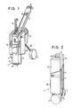
- Figur 1 und 2 jeweils eine perspektivische Darstellung des Golfwagens in der Gebrauchsstellung bzw. Nichtgebrauchsstellung;
Figur 3 einen Längsschnitt durch den Golfwagen in der Nichtgebrauchsstellung;Figur 4 eine Vorderansicht des Golfwagens in der Nichtgebrauchsstellung;Figur 5 und 6 jeweils einen Schnitt entlang der Linie A-A bzw. B-B inFigur 4;- Figur 7 den Schieber im Querschnitt; und
Figur 8 eine Draufsicht auf die Sperrklinke und die Sperrklinkenbetätigungseinrichtung.
- Figures 1 and 2 each show a perspective view of the golf cart in the use position or non-use position;
- Figure 3 shows a longitudinal section through the golf cart in the non-use position;
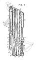
- Figure 4 is a front view of the golf cart in the non-use position;
- 5 and 6 each show a section along the line AA or BB in Figure 4;
- Figure 7 shows the slide in cross section; and
- Figure 8 is a plan view of the pawl and pawl actuator.
Gemäß Figur 1, welche die Gebrauchsstellung des Golfwagens zeigt, weist der Golfwagen einen quaderförmigen mittleren Behälter 1, ausgeschwenkte Laufräder 2, 3 und eine ausgeklappte Deichsel 4 mit einer Ausnehmung 5 zur Ausbildung eines Handgriffs 6 auf. An der Deichsel 4 ist ferner ein Scoreboard 7 und eine Aufnahme 8 für einen Sonnenschirm vorgesehen.According to Figure 1, which shows the position of use of the golf cart, the golf cart has a cuboid central container 1, swung out
Der Behälter 1 ist an seiner Oberseite durch eine mit Löchern 9 versehene Platte 10, die von der Vorderseite, an der die Deichsel 4 angeordnet ist, nach hinten schräg abfällt, und unten durch einen senkrecht zu den Seitenwänden 11 und 12 und der Rückwand 13 verlaufenden Boden 14 verschlossen.The container 1 is on its top by a
In die Löcher 9 der Platte 10 sind Golfschläger 15 gesteckt, die sich bis zum Boden 14 erstrecken.In the
Der Golfwagen ist ferner mit Taschen 16, 17 und 18 versehen, die lösbar an den Seitenwänden 11, 12 und der Rückwand 13 am Behälter 1 befestigt sind, Z.B. mit Riemen, Clips oder Klettenverschlüssen.The golf cart is also provided with
Die Räder 2, 3 werden von Beinen 19, 20 getragen, wobei in Figur 1 nur das Bein 20 des vorderen Rades 3 sichtbar ist. Die in der Gebrauchsstellung nach außen geschwenkten Beine 19, 20 verlaufen nach unten schräg auseinanderstrebend.The
In der in Figur 2 dargestellten Nichtgebrauchsstellung des Golfwagens ist die Deichsel 4 an die Vorderwand 21 des Behälters 1 geklappt und die Räder 2, 3 sind an die beiden Seitenwände 11, 12 geschwenkt. Ferner ist auf der Oberseite des Behältes 1 eine Schutzhaube 22 angeordnet, an der beidseitig weitere Taschen 23 und 24 lösbar befestigt sind.In the non-use position of the golf cart shown in FIG. 2, the
Es ist ersichtlich, daß der Golfwagen in der in Figur 2 gezeigten Nichtgebrauchsstellung sehr kompakt oder raumsparend aufgebaut ist, also z.B. im Kofferraum eines Kraftfahrzeuges transportierbar ist. Zum Heben des Golfwagens in der Nichtgebrauchsstellung sind an der Oberseite der Schutzhaube 22 und in der Mitte der Rückwand 13 des Behälters 1 jeweils Tragegriffe 25, 26 vorgesehen. Ferner weist der Boden 14 Griffmulden 27, 28 auf, die in Figur 3 gezeigt sind.It can be seen that the golf cart is very compact or space-saving in the non-use position shown in Figure 2, e.g. is transportable in the trunk of a motor vehicle. To lift the golf cart in the non-use position, carrying
Die breite plattenförmige Deichsel 4 dient z.B. beim Transport im Kofferraum als robuste definierte Auflagefläche. Sie bildet zugleich eine Gleitkufe zusammen mit den aus der Vorderwand 21 vorstehenden Rädern 2, 3.The wide plate-
Da die Räder 2, 3 mit ihrem unteren Ende bündig mit dem Boden 14 des Behälters 1 abschließen, steht der Golfwagen in der in Figur 2 gezeigten Nichtgebrauchsstellung sicher auf dem Behälterboden 14. Falls der Golfwagen in dieser Stellung bewegt werden soll, braucht er lediglich nach vorne gekippt zu werden, wodurch die Räder 2, 3 mit dem Boden in Berührung kommen. Mit dem Griff 25 kann der Golfwagen dann auf den Rädern 2, 3 problemlos gezogen werden. Erforderlich dazu ist, daß die Räder 2, 3 sowohl in der Gebrauchsstellung gemäß Figur 1, also ausgeschwenkt, wie in der Nichtgebrauchsstellung nach Figur 2, also eingeschwenkt, zueinander eine im wesentlichen parallele Laufrichtung besitzen, also die Radachsen 31 beider Räder 2, 3 miteinander fluchten oder koaxial angeordnet sind, wie für die Nichtgebrauchsstellung in Figur 4 gezeigt.Since the lower ends of the
Gemäß Figur 3 bis 5 ist der Behälter 1 an einem Fahrwerkträger 29 befestigt. Der Fahrwerkträger 29 ist, wie insbesondere aus Figur 5 hervorgeht, in einer Öffnung 30 in der Vorderwand 21 des Behälters 1 angeordnet und am Behälter 1 befestigt.According to Figures 3 to 5, the container 1 is attached to a
In gleicher Weise ist ein Griffträger 33, an dem die Deichsel 4 um die waagrechte Achse 34 verschwenkbar befestigt ist, am Behälter 1 befestigt.In the same way, a handle support 33, on which the
Am Fahrwerkträger 29 sind die Beine 19, 20 angelenkt. Die Beine 19, 20 weisen jeweils zwei als Parallellenker ausgebildete Streben 35, 36 bzw. 37, 38 auf.The
Die beiden Streben 35, 36 und 37, 38 jedes Beines 19, 20 sind an den mittleren, V-förmig zueinander verlaufenden Flanken 39, 40 des Fahrwerkträgers 29 an Achsen 41, 42 bzw. 43, 44 angelenkt. Ein im Querschnitt V-förmiges Teil 45, das am Fahrwerkträger 29 befestigt und zwischen den Flanken 39, 40 angeordnet ist, stützt die Achsen 41, 42, 43 und 44 an ihrem anderen Ende ab.The two struts 35, 36 and 37, 38 of each
Der Fahrwerkträger 29 ist relativ weit oben und, bezogen auf deren Breite, in der Mitte der Behältervorderwand 21 vorgesehen. Dadurch nehmen die Streben 35, 36 in der in Figur 3 strichliert angedeuteten Gebrauchsstellung einen relativ kleinen Winkel von 45° oder weniger gegenüber der Behälterlängsachse 46 ein.The
Die beiden Streben 35, 36 und 37, 38 jedes Beines 19, 20 sind unten mit einem Radträger 47, 48 versehen, der insbesondere aus Figur 4 und 6 ersichtlich ist. Die Radträger 47, 48 sind winkelförmig ausgebildet und umgreifen die Seitenwände 11, 12 des Behälters 1.The two struts 35, 36 and 37, 38 of each
Jeder Radträger 47, 48 weist dazu einen Schenkel 49, 50 auf, der das zugehörige Rad 2 bzw. 3 trägt und in der Nichtgebrauchsstellung an der Behälterseitenwand 11 bzw. 12 angeordnet ist, und einen Schenkel 51, 52, an o. die Beine 19, 20 angelenkt sind und der in der Nichtgebrauchsstellung an der Vorderwand 21 des Behälters 1 angeordnet ist.For this purpose, each
An der Lagerung der beiden Streben 35, 36 bzw. 37, 38 weist jeder Radträger 47, 48 am Schenkel 51, 52 kopfförmige Verdickungen 53, 54 auf, die jeweils mit einer Ausnehmung 55, 56 versehen sind, durch die sich die Achsen 57, 58 und 59, 60 erstrecken, um die die Streben 35, 36 und 37, 38 drehbar befestigt sind.On the mounting of the two
Die Achsen 57, 58 und 59, 60 der Streben 35, 36 und 37, 38 (Figur 6) verlaufen parallel zu den zugehörigen Achsen 41, 42 und 43, 44 am Fahrwerkträger 29 am anderen Ende jeder Strebe 35, 36 und 37, 38 (Figur 5). Abgesehen von den kopfförmigen Verdickungen 53, 54 sind die Radträger 47, 48 flach ausgebildet.The
In der Nichtgebrauchsstellung erstrecken sich die Streben 35, 36, 37 und 38 nahe aneinander in der Mitte der Vorderwand 21 des Behälters 1 parallel zur Behälterlängsachse 46 vom Fahrwerkträger 29 nach unten zu den kopfförmigen Verdickungen 53, 54 der Radträger 47, 48.In the non-use position, the
Auf diese Weise werden sie in Nichtgebrauchsstellung von der breiten, plattenförmigen Deichsel 4 völlig abgedeckt, und zwar einschließlich der kopfförmigen Verdickungen 53, 54.In this way, they are completely covered in the non-use position by the wide, plate-shaped
Die seitlichen Schenkel 49, 50 der beiden winkelförmigen Radträger 47, 48 erstrecken sich, wie aus Figur 3 und 4 ersichtlich, in der Nichtgebrauchsstellung von den Schenkeln 51, 52 an der Vorderwand 21 schräg nach unten zu den Achsen der Räder 2, 3. Dadurch wird den kopfförmigen Verdickungen 53, 54 bzw. der dieselben abdeckenden Deichsel 4 ein ausreichender Abstand vom Boden verliehen, wenn der Wagen in der gekippten Nichtgebrauchsstellung gezogen wird. Damit der Boden 14 in diesem gekippten Zustand nicht am Boden aufsteht, weist der Behälter 1 zwischen Vorderwand 21 und Boden 14 ferner eine Anphasung oder Abschrägung 32 auf.The
Damit die Deichsel 4 möglichst eng an den Streben 35, 36, 37 und 38 anliegen kann, wird die Ausnehmung 5 am Handgriff 6 zur Aufnahme der Verdickungen 53, 54 ausgenutzt. Die Deichsel 4 erhält dadurch ferner eine gut manövrierbare Länge im Gegensatz zu einer längeren Deichsel, wie sie bei längeren Streben 35, 36, 37 und 38, d.h. waagrecht und nicht schräg nach unten verlaufenden Schenkeln 49, 50 erforderlich wäre.So that the
Die Beine 19, 20 werden beim Ausklappen der Deichsel 4 von der in Figur 2 bis 6 gezeigten Nichtgebrauchsstellung in die in Figur 1 gezeigte Gebrauchsstellung ausgeschwenkt und eingeschwenkt, wenn die Deichsel 4 an den Behälter 1 geklappt wird.When the
Die dafür vorgesehene Einrichtung weist einen am Fahrwerkträger 29 geführten Schieber 61 auf, wie insbesondere aus Figur 3 und 7 ersichtlich. Der Schieber 61 ist dazu mit zwei Bolzen 62, 63 versehen, die durch ein parallel zur Behälterlängsachse 46 sich erstreckendes Langloch 64 in der Mitte des Fahrwerkträgers 29 ragen. Die Bolzen 62, 63 werden z.B. mit Sprengringen 65, 66 gehalten.The device provided for this purpose has a
Wie aus Figur 7 ersichtlich, weist der Schieber 61 zwei zur Behältervorderwand 21 senkrechte parallele Schenkel 67, 68 und zwei V-förmig zueinander angeordnete Schenkel 69, 70 auf.As can be seen from FIG. 7, the
An den parallelen Schenkeln 67, 68 des Schiebers 61 ist eine Zugstrebe 71 drehbar befestigt, die mit ihrem anderen Ende an der Deichsel 4 im Abstand von deren Drehachse 34 angelenkt ist. Die Drehachsen 72, 73, um die die Zugstrebe 71 drehbar an dem Schieber 61 bzw. der Deichsel 4 angelenkt ist, verlaufen waagrecht und parallel zur Vorderwand 21 des Behälters 1.On the
An den V-förmig zueinander verlaufenden Schenkeln 69, 70 des Schiebers 61 ist jeweils eine Stützstrebe 74, 75 angelenkt, welche mit ihrem anderen Ende im Abstand von den Drehachsen 41, 42, 43 und 44, an denen die Streben 35, 36, 37 und 38 an dem Fahrwerkträger 29 angelenkt sind, an der dem Behälter zugewandten Strebe 35, 37 jedes Beines 19, 20 angelenkt sind. Die Achsen 41 und 42, um die die Streben 35, 37 am Fahrwerkträger 29 drehbar sind und die Achsen 76, 77, um die die Streben 35, 37 am Schieber 61 drehbar sind, verlaufen jeweils parallel zueinander.A
Die Stützstreben 74, 75 dienen zugleich zur Stabilisierung der Beine 19, 20 in der Gebrauchsstellung, also im ausgeschwenkten Zustand, zumal die Beine 19, 20, relativ lang sind und in einem relativ spitzen Winkel von 45° oder weniger, vorzugsweise etwa 40° zur Behälterlängsachse 46 verlaufen, wie vorstehend erwähnt.The support struts 74, 75 also serve to stabilize the
Die Deichsel 4 ist in ihrer ausgeklappten, in Figur 3 gestrichelt angedeuteten Stellung zur Behälterlängsachse 46 in einem Winkel von 150° oder weniger, vorzugsweise etwa 120° angeordnet. Dieser Winkel entspricht zum einen der Ergonomie beim Ziehen des Wagens, zum anderen führt ein größerer Winkel nur noch zu einer relativ geringen Verschiebung des Schiebers 61 im Langloch 64.In its unfolded position, indicated by dashed lines in FIG. 3, the
Zur Arretierung der Deichsel 4 und damit der Beine 19, 20 in ausgeklappter bzw. herausgeschwenkter Stellung, also in der Gebrauchsstellung des Wagens gemäß Figur 1 ist am Fahrwerkträger 29 oberhalb des Langlochs 64 eine Sperrklinke 78 um eine Achse 79 verschwenkbar befestigt, wie aus Figur 3 und 8 ersichtlich.To lock the
Die Sperrklinke 78 ist mit einer Ausnehmung 80 an dem von der Drehachse 79 abgewandten unteren Ende versehen, welche am oberen Ende des Langlochs 64 angeordnet ist.The
Der obere Führungsbolzen 62 des Schiebers 61 ist in die Ausnehmung 80 einrastbar, d.h. er dient zugleich als Verriegelungsbolzen, wenn er gegen die schräge Auflaufkante 81 der Sperrklinke 78 gedrückt wird, wenn der Schieber 61 beim Ausklappen der Deichsel 4 mittels der Zugstrebe 71 zum oberen Ende des Langlochs 64 geschoben wird.The
Zum Entriegeln der Sperrklinke 78 ist, wie insbesondere aus Figur 3 und 8 ersichtlich, ein plattenförmiges Klinkenbetätigungsteil 82 über der Sperrklinke 78 angeordnet und im Abstand von der Drehachse 79 an der Sperrklinke 78 bei 83 angelenkt. Das Betätigungsteil 82 ist parallel zur Behälterlängsachse 46 am Fahrwerkträger 21 verschiebbar befestigt. Eine einerseits am Betätigungsteil 82 und andererseits am Fahrwerkträger 29 befestigte Feder 84 belastet die Sperrklinke 78 in die Verriegelungsstellung.To unlock the
Zur Führung des Betätigungsteils 82 ist an dem Fahrwerkträger 29 ein Bolzen 85 befestigt, der sich durch eine Längsausnehmung 86 im Betätigungsteil 82 erstreckt und das Betätigungsteil 82 mit einem Gleitlager 87 hält.To guide the
Am oberen Ende des Betätigungsteils 82 befindet sich ein Griff 88, der unterhalb der Drehachse 34 der Deichsel 4 und oberhalb des W-förmigen Teils 31 am Fahrwerkträger 29 angeordnet und daher bei ausgeklappter Deichsel 4 gut zugänglich ist.At the upper end of the
Wie aus Figur 3 und 5 ersichtlich, erstreckt sich im Behälter 1 von jedem Loch 9 in der Platte 10 ein Rohr 89 zum Boden 14. Die Rohre 89 sind schräg angeordnet, so daß sie nach unten zusammenlaufen. Das untere Ende der Rohre 89 wird durch die sickenförmigen Griffmulden 27, 28 fixiert.3 and 5, a
Wie aus Figur 3 ersichtlich, weist der Golfwagen ferner einen integrierten Klappsitz 90 auf. Der Klappsitz 90 ist dazu in einer Ausnehmung an der Rückwand 13 in der unteren Hälfte des Behältes 1 um eine waagrechte Achse 91 verschwenkbar befestigt.As can be seen from FIG. 3, the golf cart also has an integrated folding seat 90. For this purpose, the folding seat 90 is fastened in a recess on the
An seinem von der Schwenkache 91 abgewandten Ende ist am Klappsitz 90 eine Stützstange 92 angelenkt, die sich in der in Figur 3 mit ausgezogenen Linien dargestellten Stellung bei eingeklappten Sitz 90 zwischen den Rohren 89 schräg nach oben zur Vorderwand 21 des Behältes 1 erstreckt.At its end facing away from the
In der in Figur 3 gestrichelt dargestellten Stellung mit ausgeklapptem Sitz 90 stützt sich die Stützstange 92 hingegen an der eingewölbten Griffmulde 27 ab.In contrast, in the position shown in broken lines in FIG. 3 with the seat 90 unfolded, the
Statt der gezeigten Stützstange 92 kann der Sitz 90 auch durch eine Stange gestützt werden, die am unteren Ende des Behälters 1 angelenkt ist und an einer Aufnahme an dem von der Schwenkachse 91 abgewandten Ende des Sitzes 90 angreift.Instead of the
Claims (8)
Priority Applications (1)
| Application Number | Priority Date | Filing Date | Title |
|---|---|---|---|
| AT88112476T ATE62825T1 (en) | 1988-08-01 | 1988-08-01 | GOLF CART. |
Applications Claiming Priority (1)
| Application Number | Priority Date | Filing Date | Title |
|---|---|---|---|
| DE19873705187 DE3705187A1 (en) | 1987-02-18 | 1987-02-18 | GOLF CAR |
Publications (2)
| Publication Number | Publication Date |
|---|---|
| EP0353320A1 true EP0353320A1 (en) | 1990-02-07 |
| EP0353320B1 EP0353320B1 (en) | 1991-04-24 |
Family
ID=6321271
Family Applications (1)
| Application Number | Title | Priority Date | Filing Date |
|---|---|---|---|
| EP88112476A Expired - Lifetime EP0353320B1 (en) | 1987-02-18 | 1988-08-01 | Golf caddy |
Country Status (4)
| Country | Link |
|---|---|
| US (1) | US4890856A (en) |
| EP (1) | EP0353320B1 (en) |
| DE (1) | DE3705187A1 (en) |
| ES (1) | ES2110942T3 (en) |
Cited By (3)
| Publication number | Priority date | Publication date | Assignee | Title |
|---|---|---|---|---|
| EP0570653A1 (en) * | 1992-05-18 | 1993-11-24 | Roberto Piazzi | Motor vehicle for golf foreseen its size reduction |
| FR2698010A1 (en) * | 1992-11-19 | 1994-05-20 | Boudios Bertrand | Set trolley-cart for golf player. |
| FR2698011A1 (en) * | 1992-11-19 | 1994-05-20 | Boudios Bertrand | Combined golf bag and trolley |
Families Citing this family (31)
| Publication number | Priority date | Publication date | Assignee | Title |
|---|---|---|---|---|
| DE3705187A1 (en) * | 1987-02-18 | 1988-09-01 | Sportive Design Gmbh | GOLF CAR |
| US5071147A (en) * | 1990-08-08 | 1991-12-10 | Dan Stansbury | Device for protectively storing and transporting golf equipment |
| US5074576A (en) * | 1990-09-24 | 1991-12-24 | Finlay Richard O | Combination container and cart |
| US5478097A (en) * | 1994-10-25 | 1995-12-26 | Forma; Warren | Golf bag with retractable wheel system |
| US5725351A (en) * | 1996-06-18 | 1998-03-10 | Guibert; Chris P. | Golf accessory bag for golf pull carts |
| US6186522B1 (en) * | 1997-02-21 | 2001-02-13 | Raymond P. Weis | Travelling golf cart |
| US6330944B1 (en) | 1997-10-08 | 2001-12-18 | Demichele Christopher J. | Multi-function golf bag |
| US6050592A (en) * | 1998-03-23 | 2000-04-18 | Kim; Hyung Ho | Combined golf bag and collapsible golf cart |
| US6698789B2 (en) * | 2000-02-04 | 2004-03-02 | Sun Mountain Sports, Inc. | Collapsible golf cart |
| US6550793B2 (en) | 2001-03-16 | 2003-04-22 | Wallace T. Carter | One-piece molded/copolymeric wheeled display case |
| DE10116052C1 (en) | 2001-03-30 | 2002-11-28 | Ewald Metten | golf bag |
| EP2244200A3 (en) | 2001-08-03 | 2011-04-27 | Hill-Rom Services, Inc. | Patient point-of-care computer system |
| US6634496B2 (en) * | 2001-08-17 | 2003-10-21 | Salvatore Scoglio | Universal golf club carrier |
| US6988738B2 (en) * | 2002-02-06 | 2006-01-24 | Hi-Mark International Design Inc. | Combination unit of a golf cart and a golf bag |
| US8141905B2 (en) * | 2002-11-08 | 2012-03-27 | Ball William T | Ski equipment tote |
| US20040178591A1 (en) * | 2003-03-11 | 2004-09-16 | Rockow Gary A. | Combination golf cart and carry bag |
| US20050140103A1 (en) * | 2003-12-30 | 2005-06-30 | Marchant Michael D. | Carrying bag for folding chair |
| US8764030B1 (en) | 2004-06-04 | 2014-07-01 | Golf-N-Go, L.L.C. | Sports bag with integral transportation system |
| US7934729B2 (en) * | 2004-06-04 | 2011-05-03 | Golf-N-Go, L.L.C. | Sports bag with integral transportation system |
| US7287765B2 (en) * | 2004-06-04 | 2007-10-30 | Murphy Howard L | Sports bag with integral transportation system |
| US7419037B2 (en) * | 2004-07-06 | 2008-09-02 | Trg Accessories, Llc | Equipment carrier with a rotatable handle |
| WO2006071815A1 (en) * | 2004-12-23 | 2006-07-06 | Sutter James L | Golf bag with club positioning system |
| WO2007033674A1 (en) * | 2005-09-21 | 2007-03-29 | Nordict A/S | A ground rollable support for a golf bag, and a wheel structure for a mobile appliance |
| KR200418135Y1 (en) * | 2006-02-15 | 2006-06-08 | 주식회사 킹대일 | Carrier for golfbag |
| US7740135B2 (en) * | 2006-11-03 | 2010-06-22 | Frank E. Taylor | Article of manufacture for carrying and storing golf clubs and related accessories required to play golf |
| TWM319774U (en) * | 2007-05-04 | 2007-10-01 | Shao-Ling Ting | Golf trolley |
| US8933131B2 (en) * | 2010-01-12 | 2015-01-13 | The Procter & Gamble Company | Intermediates and surfactants useful in household cleaning and personal care compositions, and methods of making the same |
| EP2374439A3 (en) | 2010-04-09 | 2015-11-25 | Hill-Rom Services, Inc. | Patient support, communication, and computing apparatus |
| US20140061075A1 (en) * | 2012-08-28 | 2014-03-06 | Callaway Golf Company | Golf bag having adjustable characteristics |
| US9539155B2 (en) | 2012-10-26 | 2017-01-10 | Hill-Rom Services, Inc. | Control system for patient support apparatus |
| US10474808B2 (en) | 2013-03-29 | 2019-11-12 | Hill-Rom Services, Inc. | Hospital bed compatibility with third party application software |
Citations (6)
| Publication number | Priority date | Publication date | Assignee | Title |
|---|---|---|---|---|
| GB693758A (en) * | 1950-05-24 | 1953-07-08 | Peter Pan Mfg Co Ltd | Improvements in wheeled carriers, particularly for golf clubs |
| US2770466A (en) * | 1955-03-28 | 1956-11-13 | Anthony P Pearson | Golf cart with collapsible wheel structure |
| US3489426A (en) * | 1969-01-14 | 1970-01-13 | John R J Bond | Combination golf cart and golf bag |
| GB1295246A (en) * | 1968-11-21 | 1972-11-08 | ||
| DE8508855U1 (en) * | 1985-03-25 | 1985-05-15 | Monfort, Michael M., 4130 Moers | Golf carts, in particular foldable golf carts |
| DE3705187A1 (en) * | 1987-02-18 | 1988-09-01 | Sportive Design Gmbh | GOLF CAR |
Family Cites Families (11)
| Publication number | Priority date | Publication date | Assignee | Title |
|---|---|---|---|---|
| US2428954A (en) * | 1945-11-19 | 1947-10-14 | Albert V Apblett | Golf equipment holder and carrier |
| US3043602A (en) * | 1958-10-08 | 1962-07-10 | Meiklejohn Ian Goodhall | Wheeled carriers, especially golf-bag carriers |
| GB882481A (en) * | 1959-04-27 | 1961-11-15 | Edward Roy Jarman | Golf bag |
| GB941603A (en) * | 1962-09-21 | 1963-11-13 | Shelford Engineering Company L | Golf bag trolley |
| US3150881A (en) * | 1963-05-02 | 1964-09-29 | Vaughn E Van Skyock | Combination golf bag and cart |
| US3167146A (en) * | 1963-05-08 | 1965-01-26 | Rome R Rudolph | Power driven golf cart |
| GB1228970A (en) * | 1968-08-15 | 1971-04-21 | ||
| GB1284919A (en) * | 1971-11-17 | 1972-08-09 | Herbert Francis Potter | Trolley golf bag |
| US4078594A (en) * | 1976-02-03 | 1978-03-14 | Otto Oeckl | Container for golf clubs |
| DE3171752D1 (en) * | 1981-01-02 | 1985-09-19 | Goran Rosen | Manually propelled golf trolley |
| US4522299A (en) * | 1984-01-23 | 1985-06-11 | 434743 Ontario Inc. | Rigid polyethylene carry golf bag with stand |
-
1987
- 1987-02-18 DE DE19873705187 patent/DE3705187A1/en active Granted
-
1988
- 1988-02-17 US US07/157,512 patent/US4890856A/en not_active Expired - Fee Related
- 1988-08-01 ES ES88112476T patent/ES2110942T3/en not_active Expired - Lifetime
- 1988-08-01 EP EP88112476A patent/EP0353320B1/en not_active Expired - Lifetime
Patent Citations (6)
| Publication number | Priority date | Publication date | Assignee | Title |
|---|---|---|---|---|
| GB693758A (en) * | 1950-05-24 | 1953-07-08 | Peter Pan Mfg Co Ltd | Improvements in wheeled carriers, particularly for golf clubs |
| US2770466A (en) * | 1955-03-28 | 1956-11-13 | Anthony P Pearson | Golf cart with collapsible wheel structure |
| GB1295246A (en) * | 1968-11-21 | 1972-11-08 | ||
| US3489426A (en) * | 1969-01-14 | 1970-01-13 | John R J Bond | Combination golf cart and golf bag |
| DE8508855U1 (en) * | 1985-03-25 | 1985-05-15 | Monfort, Michael M., 4130 Moers | Golf carts, in particular foldable golf carts |
| DE3705187A1 (en) * | 1987-02-18 | 1988-09-01 | Sportive Design Gmbh | GOLF CAR |
Cited By (4)
| Publication number | Priority date | Publication date | Assignee | Title |
|---|---|---|---|---|
| EP0570653A1 (en) * | 1992-05-18 | 1993-11-24 | Roberto Piazzi | Motor vehicle for golf foreseen its size reduction |
| FR2698010A1 (en) * | 1992-11-19 | 1994-05-20 | Boudios Bertrand | Set trolley-cart for golf player. |
| FR2698011A1 (en) * | 1992-11-19 | 1994-05-20 | Boudios Bertrand | Combined golf bag and trolley |
| WO1994011065A1 (en) * | 1992-11-19 | 1994-05-26 | Bertrand Boudios | Bag and cart assembly for golfers |
Also Published As
| Publication number | Publication date |
|---|---|
| DE3705187C2 (en) | 1991-07-04 |
| EP0353320B1 (en) | 1991-04-24 |
| US4890856A (en) | 1990-01-02 |
| ES2110942T3 (en) | 1998-03-01 |
| DE3705187A1 (en) | 1988-09-01 |
Similar Documents
| Publication | Publication Date | Title |
|---|---|---|
| EP0353320B1 (en) | Golf caddy | |
| DE3423528C2 (en) | Dolly | |
| DE10080836B4 (en) | Convertible skateboard / scooter device | |
| DE19534974A1 (en) | Collapsible cart | |
| EP0584135A1 (en) | Transport device | |
| DE3719730A1 (en) | FOLDING SEAT | |
| DE1655799B1 (en) | Device for locking containers on the loading area of a vehicle | |
| DE2516513A1 (en) | HAND CART CHASSIS WITH FOLDING WHEELS | |
| DE202022102086U1 (en) | Foldable wagon with foldable tabletop | |
| DE19707744C1 (en) | Folding transport trolley for shopping trolley, transport chest, vehicle trailer | |
| DE19856848C2 (en) | Clutch-bound vehicle rear carrier | |
| DE4241142A1 (en) | Device to fit rear load carrier to motor vehicle, esp. car | |
| EP0207419B1 (en) | Tool box | |
| DE3318891A1 (en) | Two-part estate car roof rack | |
| DE10050783C2 (en) | Mobile suitcase or container | |
| DE3202881A1 (en) | Two-wheel bicycle trailer which has a loading area mounted in a frame and can be attached to a bicycle by means of a tow bar | |
| DE102018110024B4 (en) | Collapsible wheelbarrow for transporting stacked goods | |
| EP1448073A1 (en) | Transport device for luggage items or similar | |
| WO1998056640A1 (en) | Skibob | |
| DE102020108026B3 (en) | Transport device for a plate compactor | |
| DE4201215C1 (en) | ||
| DE69923772T2 (en) | TRANSPORT PROTECTION DEVICE | |
| DE10342923A1 (en) | Collapsible golf caddy has a box shaped container with compartments for demountable wheels and supports and with a retracting hand grip | |
| EP1467903A2 (en) | Collapsible transport vehicle | |
| CH719406A1 (en) | Golf bag and golf trolley, as well as golf bag-golf trolley unit. |
Legal Events
| Date | Code | Title | Description |
|---|---|---|---|
| PUAI | Public reference made under article 153(3) epc to a published international application that has entered the european phase |
Free format text: ORIGINAL CODE: 0009012 |
|
| 17P | Request for examination filed |
Effective date: 19890603 |
|
| AK | Designated contracting states |
Kind code of ref document: A1 Designated state(s): AT CH ES FR GB IT LI SE |
|
| 17Q | First examination report despatched |
Effective date: 19900709 |
|
| GRAA | (expected) grant |
Free format text: ORIGINAL CODE: 0009210 |
|
| AK | Designated contracting states |
Kind code of ref document: B1 Designated state(s): AT CH ES FR GB IT LI SE |
|
| PG25 | Lapsed in a contracting state [announced via postgrant information from national office to epo] |
Ref country code: SE Effective date: 19910424 |
|
| REF | Corresponds to: |
Ref document number: 62825 Country of ref document: AT Date of ref document: 19910515 Kind code of ref document: T |
|
| ITF | It: translation for a ep patent filed |
Owner name: ING. PIOVESANA PAOLO |
|
| GBT | Gb: translation of ep patent filed (gb section 77(6)(a)/1977) | ||
| ET | Fr: translation filed | ||
| PG25 | Lapsed in a contracting state [announced via postgrant information from national office to epo] |
Ref country code: LI Effective date: 19910831 Ref country code: CH Effective date: 19910831 |
|
| PLBE | No opposition filed within time limit |
Free format text: ORIGINAL CODE: 0009261 |
|
| STAA | Information on the status of an ep patent application or granted ep patent |
Free format text: STATUS: NO OPPOSITION FILED WITHIN TIME LIMIT |
|
| 26N | No opposition filed | ||
| REG | Reference to a national code |
Ref country code: CH Ref legal event code: PL |
|
| PGFP | Annual fee paid to national office [announced via postgrant information from national office to epo] |
Ref country code: LU Payment date: 19940731 Year of fee payment: 6 |
|
| EPTA | Lu: last paid annual fee | ||
| PGFP | Annual fee paid to national office [announced via postgrant information from national office to epo] |
Ref country code: FR Payment date: 19970718 Year of fee payment: 10 |
|
| PGFP | Annual fee paid to national office [announced via postgrant information from national office to epo] |
Ref country code: GB Payment date: 19970723 Year of fee payment: 10 |
|
| PGFP | Annual fee paid to national office [announced via postgrant information from national office to epo] |
Ref country code: ES Payment date: 19970801 Year of fee payment: 10 |
|
| PGFP | Annual fee paid to national office [announced via postgrant information from national office to epo] |
Ref country code: AT Payment date: 19970814 Year of fee payment: 10 |
|
| REG | Reference to a national code |
Ref country code: ES Ref legal event code: FG2A Ref document number: 2110942 Country of ref document: ES Kind code of ref document: T3 |
|
| PG25 | Lapsed in a contracting state [announced via postgrant information from national office to epo] |
Ref country code: GB Free format text: LAPSE BECAUSE OF NON-PAYMENT OF DUE FEES Effective date: 19980801 Ref country code: AT Free format text: LAPSE BECAUSE OF NON-PAYMENT OF DUE FEES Effective date: 19980801 |
|
| PG25 | Lapsed in a contracting state [announced via postgrant information from national office to epo] |
Ref country code: ES Free format text: LAPSE BECAUSE OF THE APPLICANT RENOUNCES Effective date: 19980803 |
|
| GBPC | Gb: european patent ceased through non-payment of renewal fee |
Effective date: 19980801 |
|
| PG25 | Lapsed in a contracting state [announced via postgrant information from national office to epo] |
Ref country code: FR Free format text: LAPSE BECAUSE OF NON-PAYMENT OF DUE FEES Effective date: 19990430 |
|
| REG | Reference to a national code |
Ref country code: FR Ref legal event code: ST |
|
| REG | Reference to a national code |
Ref country code: ES Ref legal event code: FD2A Effective date: 20001102 |
|
| PG25 | Lapsed in a contracting state [announced via postgrant information from national office to epo] |
Ref country code: IT Free format text: LAPSE BECAUSE OF NON-PAYMENT OF DUE FEES;WARNING: LAPSES OF ITALIAN PATENTS WITH EFFECTIVE DATE BEFORE 2007 MAY HAVE OCCURRED AT ANY TIME BEFORE 2007. THE CORRECT EFFECTIVE DATE MAY BE DIFFERENT FROM THE ONE RECORDED. Effective date: 20050801 |