EP0352428B1 - Collapsible hood for vehicle - Google Patents
Collapsible hood for vehicle Download PDFInfo
- Publication number
- EP0352428B1 EP0352428B1 EP89109350A EP89109350A EP0352428B1 EP 0352428 B1 EP0352428 B1 EP 0352428B1 EP 89109350 A EP89109350 A EP 89109350A EP 89109350 A EP89109350 A EP 89109350A EP 0352428 B1 EP0352428 B1 EP 0352428B1
- Authority
- EP
- European Patent Office
- Prior art keywords
- collapsible
- collapsible hood
- column portion
- hood
- hood according
- Prior art date
- Legal status (The legal status is an assumption and is not a legal conclusion. Google has not performed a legal analysis and makes no representation as to the accuracy of the status listed.)
- Expired - Lifetime
Links
Images


Classifications
-
- B—PERFORMING OPERATIONS; TRANSPORTING
- B60—VEHICLES IN GENERAL
- B60J—WINDOWS, WINDSCREENS, NON-FIXED ROOFS, DOORS, OR SIMILAR DEVICES FOR VEHICLES; REMOVABLE EXTERNAL PROTECTIVE COVERINGS SPECIALLY ADAPTED FOR VEHICLES
- B60J7/00—Non-fixed roofs; Roofs with movable panels, e.g. rotary sunroofs
- B60J7/08—Non-fixed roofs; Roofs with movable panels, e.g. rotary sunroofs of non-sliding type, i.e. movable or removable roofs or panels, e.g. let-down tops or roofs capable of being easily detached or of assuming a collapsed or inoperative position
- B60J7/12—Non-fixed roofs; Roofs with movable panels, e.g. rotary sunroofs of non-sliding type, i.e. movable or removable roofs or panels, e.g. let-down tops or roofs capable of being easily detached or of assuming a collapsed or inoperative position foldable; Tensioning mechanisms therefor, e.g. struts
- B60J7/1226—Soft tops for convertible vehicles
- B60J7/1265—Soft tops for convertible vehicles characterised by kinematic movements, e.g. using parallelogram linkages
-
- B—PERFORMING OPERATIONS; TRANSPORTING
- B60—VEHICLES IN GENERAL
- B60J—WINDOWS, WINDSCREENS, NON-FIXED ROOFS, DOORS, OR SIMILAR DEVICES FOR VEHICLES; REMOVABLE EXTERNAL PROTECTIVE COVERINGS SPECIALLY ADAPTED FOR VEHICLES
- B60J7/00—Non-fixed roofs; Roofs with movable panels, e.g. rotary sunroofs
- B60J7/0076—Non-fixed roofs; Roofs with movable panels, e.g. rotary sunroofs separately collapsible C-pillars, e.g. by folding inwardly or sliding
Definitions
- the invention relates to a folding roof for vehicles, in particular passenger cars, according to the preamble of patent claim 1.
- Such a folding top is known from DE-PS 706 684.
- all axes of rotation of the top kinematics are aligned and are perpendicular to the vertical longitudinal median plane of the passenger car.
- the rear area In order to accommodate such a folding roof completely sunk in a rear-side receiving space of the body, the rear area must have at least the same width as the greatest width of the roof.
- the object of the invention is to take such precautions on a convertible top that, on the one hand, a good circumferential seal to the adjacent side viewing window is achieved when the convertible top is closed, and that, on the other hand, the convertible top is also completely sunk in a rear-side receiving space even in the case of aerodynamically optimized bodies (rear intake) stowed away.
- the main advantages achieved with the invention can be seen in the fact that with the column section provided in the rear upright edge region of the viewing window, which is connected to the folding top by positive control, on the one hand a good sealing of the viewing window and on the other hand a reduction in the width of the folding top when swiveling back is ensured because the free end of the column section inevitably performs an inward movement.
- the inclined axis of rotation between the rear roof frame and the pillar section is decisive for this inward movement.
- the ball joints of the connecting rod cause a good one Sequence of movements without tensioning the top kinematics.
- the connecting rod fixes the pillar section in the vehicle longitudinal direction when the convertible top is closed. With this construction, the visor and the convertible top can have a large side slope (inclined position), and yet the convertible top can be easily accommodated in the receiving space - without a costly rear change.
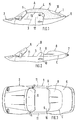
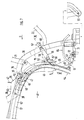
- a convertible two-seater passenger car 1 is shown, the structure 2 above a belt line 3 comprises a folding roof 4, which extends between a windshield frame 5 and a rear area 6.
- the folding top 4 is held in position in its closed position A via closures (not shown) on the windshield frame 5. After releasing the fasteners, the folding top 4 can be pivoted behind the two front seats 7.
- the folded-back convertible top 4 (open position B) is arranged below a rear cover 8 made of plastic, the rear cover 8 being pivoted on the body 2.
- the aerodynamically designed rear cover 8 is seen in plan view, adapted to the curved shape C of the rear contour. Laterally outer front end areas 9 of the rear cover 8 extend approximately in continuation of a rear boundary edge 10 of a side door 11.
- the door 11 is provided with a height-adjustable viewing window 12, the viewing window 12 being guided without a frame above the belt line 3.
- An overlying, approximately horizontal edge 13 of the lens 12 is supported with a closed folding top A under pretension on a seal attached to the folding top 4, not shown.
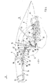
- the folding roof 4 is composed of a convertible top frame 14 and a convertible top cover 15, a flexible or rigid rear window 16 being provided adjacent to the rear region 6 (FIGS. 1 and 4).
- the convertible top frame 14 comprises a front convertible top frame 17, a rear convertible top frame 18, a parallelogram linkage 19 engaging the rear convertible top frame 18, a front transverse bow 20, a rear transverse bow 21 and a corner bow 22 (FIG. 4).
- the front convertible top frame 17 consists of a cross member 23 running adjacent to the windshield frame 5 and two lateral front longitudinal bars 24, the two longitudinal bars 24 being firmly connected to the cross member 23 at their front end regions.
- the rear convertible top frame 18 comprises two laterally outer, rear longitudinal bars 27, each longitudinal bar 27 consisting of an inner longitudinal link 51 and an outer holding part 52.
- a seal not shown, is fastened to the holding part 52 and cooperates in a sealing manner with the viewing window 12.
- the holding part 52 is permanently connected locally to the trailing arm 51, for example by welding. 4, the holding part 52 is adapted to the curved shape of the upper edge 13 of the lens 12, while the trailing arm 51 is rectilinear.
- the front convertible top frame 17 is articulated at 25 to the rear convertible top frame 18, the articulated axis 25 being oriented horizontally and extending in the transverse direction of the vehicle.
- the hinge axis 25 connects a bearing 26 provided on the longitudinal beam 24 to the trailing arm 51.
- Each trailing arm 51 is rotatably connected to a main bow 29 in a central region of its longitudinal extent.
- the axis of rotation 28 of the Main bow 29 is aligned horizontally and extends in the vehicle transverse direction.
- the main bow 29 and a steering lever 30 located behind it in the direction of travel D form the parallelogram linkage 19 (FIG. 7).
- the main bow 29 and the steering lever 30 are rotatably articulated on a mounting plate 31 fastened on the body side.
- Both axes of rotation 32, 33 are aligned horizontally and run in the vehicle transverse direction.
- the axis of rotation 33 of the steering lever 30 is lower than the axis of rotation 32 of the main bow 29, namely below the bearing plate 31. Seen in the direction of travel D, the axis of rotation 32 lies in front of the axis of rotation 33.
- An upper end 34 of the steering lever 30 is articulated at 35 to the rear end of the trailing arm 51.
- An arm 36 of the main bow 29 lying above the pivot point 28 interacts with a lever 37, one end 38 of which is rotatably articulated on the bearing 26 of the longitudinal beam 24.
- the other articulation point 39 of the lever 37 is seen in the direction of travel D in front of the axis of rotation 28.
- the front transverse bow 20 is pivotally mounted on the lever 37 which rises obliquely from the bottom to the top in a central region of its longitudinal extent.
- the main bow 29 has an approximately horizontally oriented section 40 adjacent to the axis of rotation 28, from which a tubular bracket 42 spanning the passenger compartment 41 is led away.
- the bracket 42 is firmly connected to the section 40, for example by welding. Furthermore, the rear cross bow 21 and the corner bow 22 are rotatably articulated on the main bow 29. The transverse bow 20, 21, the corner bow 22 and the bracket 42 are connected to one another by longitudinal straps 43 (FIG. 5).
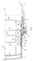
- a column section 46 is provided which, seen in the side view, runs approximately parallel to the contour of the lens 12.
- the column portion 46 is rotatably connected at its upper end 47 to a bracket 48 attached to the rear longitudinal beam 27.
- the axis of rotation 49 of the column section 46 extends below the axis of rotation 35 and viewed in the direction of travel D in front of the latter.
- the axis of rotation 49 runs in seen from the top view at an acute angle ⁇ to a vertical auxiliary plane 50, such that an outer region of the axis of rotation 49 seen in the direction of travel D lies further forward than an inner region of the axis of rotation 49 (FIG. 8).
- the common contact surface of the column section 46 and the bracket 48 can either be aligned vertically or be slightly inclined.
- the upper end 47 of the column section 46 is overlapped in sections by the holding part 52 of the longitudinal spar 27 (seen in the side view).
- the pivoted-back position of the folding top 4 is shown in broken lines in FIG. 4.
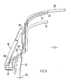
- the column section 46 is connected to the steering lever 30 in a central region of its vertical extent via a connecting member 55.
- the connecting link 55 is designed as a rod 56, the two ends of which are connected via ball joints 57 on the one hand to the steering lever 30 and on the other hand to the column section 46.
- the column-side articulation point 58 is located approximately below the articulation point 59 of the corner bow 22.
- the lower free end 54 of the column section 46 cooperates with a closed convertible top 4 with a lock 61, such that the column section 46 is fixed in the vehicle transverse direction.
- the lock 61 is formed by a longitudinal pin 62, which is oriented approximately horizontally when the convertible top 4 is closed.
- the pin 62 is formed on an angular fitting part 63 which is fastened to the column section 46 by means of screws.
- the pin 62 extends - viewed in the direction of travel D - away from the column section 46 to the rear. 7 and 8, the pin cooperates with a bow-shaped guide member 64 arranged on the construction side.
- the guide member 64 has - seen in plan view - a U-shaped end region 65, the two tubular legs 66, 67 being inclined against the direction of travel D from below run upwards.
- the leg 67 facing the vehicle longitudinal center plane EE has a greater length and a curved shape in sections.
- the guide member 64 with its longer leg 67 extends approximately over the length of the bearing plate 31
- the pin 62 is arranged between the two legs 66, 67 of the U-shaped end region 65 of the guide member 64, which are aligned in the same direction.
- the pin 62 is provided with a casing made of plastic or rubber, not shown in any more detail.
- the main bow 29 runs - seen in the side view - at a distance from the contour of the column section 46 (FIG. 6).
- the lower, approximately upright section 68 of the main bow 29 is connected to the upper, upwardly arranged upright section 70 via an inclined shelf 69.
- the ball joints 57 for the rod 56 are formed by ball sockets 71, which are screwed onto the ends 72, 73 of the rod 56 in an adjustable manner.
- the ball cups 71 are pressed onto ball heads 74 which are attached to the steering lever 30 and to the column section 46.
- the column section 46 is preferably designed as an aluminum die-cast part and seen in cross section, approximately L-shaped profile.
- the convertible top cover 15 is fixed laterally to the front convertible top frame 17 and to a lower region of the column section 46, whereas it lies against the rear convertible top frame 18 without being fastened.
- FIG. 10 shows how a sealing body 75, which interacts with the rear edge 44 of the lens 12, is fastened to the column section 46.
- the column section 46 In the folded-back position B of the folding top, the column section 46 is designated 46 '(FIGS. 4 and 5).
Description
Die Erfindung bezieht sich auf ein Klappverdeck für Fahrzeuge, insbesondere Personenkraftwagen gemäß dem Oberbegriff des Patentanspruchs 1.The invention relates to a folding roof for vehicles, in particular passenger cars, according to the preamble of
Ein derartiges Klappverdeck ist aus der DE-PS 706 684 bekannt. Bei solchen Klappverdecken sind alle Drehachsen der Verdeckkinematik gleichgerichtet und verlaufen senkrecht zur vertikalen Längsmittelebene des Personenkraftwagens. Um ein derartiges Klappverdeck vollständig versenkt in einem heckseitigen Aufnahmeraum der Karosserie unterzubringen, muß der Heckbereich zumindest die gleiche Breite aufweisen wie die größte Breite des Verdecks.Such a folding top is known from DE-PS 706 684. In such folding tops, all axes of rotation of the top kinematics are aligned and are perpendicular to the vertical longitudinal median plane of the passenger car. In order to accommodate such a folding roof completely sunk in a rear-side receiving space of the body, the rear area must have at least the same width as the greatest width of the roof.
Bei neuen, aerodynamisch optimierten Karosserien, die mit einem Heckeinzug versehen sind, ergeben sich somit große Probleme, das Verdeck versenkt in einem heckseitigen Aufnahmeraum unterzubringen.With new, aerodynamically optimized bodies that are equipped with a rear intake, there are therefore great problems in accommodating the convertible top in a rear-side receiving space.
Aufgabe der Erfindung ist es, an einem Klappverdeck solche Vorkehrungen zu treffen, daß einerseits bei geschlossenem Verdeck eine gute umfangsseitige Abdichtung zur angrenzenden seitlichen Sichtscheibe erzielt wird und daß sich das Klappverdeck andererseits auch bei aerodynamisch optimierten Karosserien (Heckeinzug) problemlos vollständig versenkt in einem heckseitigen Aufnahmeraum verstauen läßt.The object of the invention is to take such precautions on a convertible top that, on the one hand, a good circumferential seal to the adjacent side viewing window is achieved when the convertible top is closed, and that, on the other hand, the convertible top is also completely sunk in a rear-side receiving space even in the case of aerodynamically optimized bodies (rear intake) stowed away.
Erfindungsgemäß wird diese Aufgabe durch die kennzeichnenden Merkmale des Anspruchs 1 gelöst. Weitere, die Erfindung in vorteilhafter Weise ausgestaltende Merkmale sind in den Unteransprüchen enthalten.According to the invention, this object is achieved by the characterizing features of
Die mit der Erfindung hauptsächlich erzielten Vorteile sind darin zu sehen, daß mit dem im hinteren aufrechten Randbereich der Sichtscheibe vorgesehenen Säulenabschnitt, der über eine Zwangssteuerung mit dem Klappverdeck verbunden ist, einerseits eine gute Abdichtung der Sichtscheibe und andererseits eine Reduzierung der Breite des Klappverdecks beim Zurückschwenken gewährleistet ist, da das freie Ende des Säulenabschnitts zwangsweise eine Bewegung nach innen ausführt. Entscheidend für diese Bewegung nach innen ist die schrägverlaufende Drehachse zwischen dem hinteren Verdeckrahmen und dem Säulenabschnitt. Die Kugelgelenke der Verbindungsstange bewirken einen guten Bewegungsablauf ohne Verspannungen der Verdeckkinematik. Die Verbindungsstange fixiert den Säulenabschnitt bei geschlossenem Verdeck in Fahrzeuglängsrichtung. Bei dieser Konstruktion können die Sichtscheibe und das Verdeck eine große Seitenfallung (Schräglage) aufweisen und trotzdem läßt sich das Verdeck problemlos - ohne eine kostenintensive Heckänderung - im Aufnahmeraum unterbringen.The main advantages achieved with the invention can be seen in the fact that with the column section provided in the rear upright edge region of the viewing window, which is connected to the folding top by positive control, on the one hand a good sealing of the viewing window and on the other hand a reduction in the width of the folding top when swiveling back is ensured because the free end of the column section inevitably performs an inward movement. The inclined axis of rotation between the rear roof frame and the pillar section is decisive for this inward movement. The ball joints of the connecting rod cause a good one Sequence of movements without tensioning the top kinematics. The connecting rod fixes the pillar section in the vehicle longitudinal direction when the convertible top is closed. With this construction, the visor and the convertible top can have a large side slope (inclined position), and yet the convertible top can be easily accommodated in the receiving space - without a costly rear change.
Ein Ausführungsbeispiel der Erfindung ist in der Zeichnung dargestellt und wird im folgenden näher erläutert.
Es zeigt
- Fig. 1 eine Teilseitenansicht eines Personenwagens mit einem Klappverdeck in Schließstellung,
- Fig. 2 eine Teilseitenansicht auf den Personenwagen mit zurückgeschwenktem Klappverdeck,
- Fig. 3 eine Draufsicht auf die Fig. 2,
- Fig. 4 eine Teilseitenansicht auf das Verdeckgestänge des Klappverdecks in größerem Maßstab,
- Fig. 5 eine Teildraufsicht auf die Fig. 4 in größerem Maßstab,
- Fig. 6 eine Ansicht in Pfeilrichtung R der Fig. 4 in größerem Maßstab,
- Fig. 7 eine Einzelheit X der Fig. 4 in größerem Maßstab,
- Fig. 8 eine Einzelheit Y der Fig. 5 in größerem Maßstab,
- Fig. 9 einen Schnitt nach der Linie IX-IX der Fig. 7,
- Fig. 10 einen Schnitt nach der Linie X-X der Fig. 7.
It shows
- 1 is a partial side view of a passenger car with a folding top in the closed position,
- 2 is a partial side view of the passenger car with the folding top pivoted back,
- 3 is a plan view of FIG. 2,
- 4 is a partial side view of the top linkage of the folding top on a larger scale,
- 5 is a partial plan view of FIG. 4 on a larger scale,
- 6 is a view in the direction of arrow R of FIG. 4 on a larger scale,
- 7 shows a detail X of FIG. 4 on a larger scale,
- 8 shows a detail Y of FIG. 5 on a larger scale,
- 9 is a section along the line IX-IX of FIG. 7,
- 10 is a section along the line XX of FIG .. 7
In Fig. 1 ist ein umwandelbarer zweisitziger Personenwagen 1 dargestellt, dessen Aufbau 2 oberhalb einer Gürtellinie 3 ein Klappverdeck 4 umfaßt, das sich zwischen einem Windschutzscheibenrahmen 5 und einem Heckbereich 6 erstreckt. Das Klappverdeck 4 ist in seiner Schließstellung A über nicht näher dargestellte Verschlüsse am Winschutzscheibenrahmen 5 in Lage gehalten. Nach Lösen der Verschlüsse läßt sich das Klappverdeck 4 hinter die beiden Vordersitze 7 verschwenken.In Fig. 1 a convertible two-
Gemäß Fig. 2 ist das zurückgeklappte Verdeck 4 (Offenstellung B) unterhalb einer aus Kunststoff gefertigten Fondabdeckung 8 angeordnet, wobei die Fondabdeckung 8 schwenkbar am Aufbau 2 angelenkt ist. Die aerodynamisch ausgebildete Fondabdeckung 8 ist in der Draufsicht gesehen, dem bogenförmigen Verlauf C der Heckkontur angepaßt. Seitlich außenliegende vordere Endbereiche 9 der Fondabdeckung 8 verlaufen etwa in Fortsetzung einer hinteren Begrenzungskante 10 einer seitlichen Tür 11.2, the folded-back convertible top 4 (open position B) is arranged below a
Die Tür 11 ist mit einer höhenverstellbaren Sichtscheibe 12 versehen, wobei die Sichtscheibe 12 oberhalb der Gürtellinie 3 rahmenlos geführt ist. Ein obenliegender, etwa horizontal verlaufender Rand 13 der Sichtscheibe 12 stützt sich bei geschlossenem Klappverdeck A unter Vorspannung an einer am Klappverdeck 4 angebrachten, nicht näher dargestellten Dichtung ab.The
Das Klappverdeck 4 setzt sich aus einem Verdeckgestell 14 und einem Verdeckbezug 15 zusammen, wobei benachbart des Heckbereichs 6 eine flexible oder starre Heckscheibe 16 vorgesehen ist (Fig. 1 und 4). Das Verdeckgestell 14 umfaßt einen vorderen Verdeckrahmen 17, einen hinteren Verdeckrahmen 18, ein am hinteren Verdeckrahmen 18 angreifendes Parallelogramm-Gestänge 19, einen vorderen Querspriegel 20, einen hinteren Querspriegel 21 und einen Eckspriegel 22 (Fig. 4).The folding
Der vordere Verdeckrahmen 17 besteht aus einem benachbart dem Windschutzscheibenrahmen 5 verlaufenden Querträger 23 und zwei seitlichen vorderen Längsholmen 24, wobei die beiden Längsholme 24 an ihren vorderen Endbereichen fest mit dem Querträger 23 verbunden sind. Der hintere Verdeckrahmen 18 umfaßt zwei seitlich außenliegende hintere Längsholme 27, wobei jeder Längsholm 27 aus einem innenliegenden Längslenker 51 und einem außenliegenden Halteteil 52 besteht. Am Halteteil 52 ist eine nicht näher dargestellte Dichtung befestigt, die mit der Sichtscheibe 12 dichtend zusammenwirkt. Das Halteteil 52 ist örtlich fest mit dem Längslenker 51 verbunden, beispielsweise durch Schweißen. Entsprechend Fig. 4 ist das Halteteil 52 dem gebogenen Formverlauf des obenliegenden Randes 13 der Sichtscheibe 12 angepaßt, während der Längslenker 51 geradlinig ausgebildet ist.The front convertible
Gemäß Fig. 4 ist der vordere Verdeckrahmen 17 bei 25 gelenkig mit dem hinteren Verdeckrahmen 18 verbunden, wobei die Gelenkachse 25 horizontal ausgerichtet ist und in Fahrzeugquerrichtung verläuft. Die Gelenkachse 25 verbindet ein am Längsholm 24 vorgesehenes Lager 26 mit dem Längslenker 51. Jeder Längslenker 51 ist in einem mittleren Bereich seiner Längserstreckung mit einem Hauptspriegel 29 drehbar verbunden. Die Drehachse 28 des Hauptspriegels 29 ist horizontal ausgerichtet und verläuft in Fahrzeugquerrichtung. Der Hauptspriegel 29 und ein in Fahrtrichtung D gesehen dahinterliegender Lenkhebel 30 bilden das Parallelogramm-Gestänge 19 (Fig. 7). Der Hauptspriegel 29 und der Lenkhebel 30 sind an einer aufbauseitig befestigten Lagerplatte 31 drehbar angelenkt. Beide Drehachsen 32, 33 sind horizontal ausgerichtet und verlaufen in Fahrzeugquerrichtung. Die Drehachse 33 des Lenkhebels 30 liegt dabei tiefer als die Drehachse 32 des Hauptspriegels 29, und zwar unterhalb der Lagerplatte 31. In Fahrtrichtung D gesehen, liegt die Drehachse 32 vor der Drehachse 33.4, the front convertible
Ein oberes Ende 34 des Lenkhebels 30 ist bei 35 gelenkig mit dem hinteren Ende des Längslenkers 51 verbunden. Ein oberhalb des Drehpunktes 28 liegender Arm 36 des Hauptspriegels 29 wirkt mit einem Hebel 37 zusammen, dessen eines Ende 38 am Lager 26 des Längsholms 24 drehbar angelenkt ist. Der andere Anlenkpunkt 39 des Hebels 37 liegt in Fahrtrichtung D gesehen vor der Drehachse 28. Am schräg von unten nach oben ansteigenden Hebel 37 ist in einem mittleren Bereich seiner Längserstreckung der vordere Querspriegel 20 schwenkbar gelagert. Der Hauptspriegel 29 weist angrenzend an die Drehachse 28 einen etwa horizontal ausgerichteten Abschnitt 40 auf, von dem aus ein rohrförmiger, den Fahrgastraum 41 überspannender Bügel 42 weggeführt ist. Der Bügel 42 ist fest mit dem Abschnitt 40 verbunden, beispielsweise durch Verschweißen. Ferner sind am Hauptspriegel 29 der hintere Querspriegel 21 und der Eckspriegel 22 drehbar angelenkt. Die Querspriegel 20, 21, der Eckspriegel 22 und der Bügel 42 sind durch längsverlaufende Fangbänder 43 miteinander verbunden (Fig. 5).An
Damit ein hinterer, etwa aufrecht verlaufender Rand 44 der Sichtscheibe 12 bei geschlossenem Klappverdeck 4 gut abgedichtet ist, und sich das Klappverdeck 4 bei einem aus aerodynamischen Gründen mit einem Heckeinzug versehenen Personenwagen ohne Änderung des Heckbereichs 6 in einem karosserieseitigen Aufnahmeraum 45 unterbringen läßt, ist benachbart des Randes 44 ein Säulenabschnitt 46 vorgesehen, der in der Seitenansicht gesehen, etwa parallel zur Kontur der Sichtscheibe 12 verläuft. Der Säulenabschnitt 46 ist an seinem oberen Ende 47 drehbar mit einem am hinteren Längsholm 27 angebrachten Haltewinkel 48 verbunden. Die Drehachse 49 des Säulenabschnittes 46 erstreckt sich unterhalb der Drehachse 35 und in Fahrtrichtung D gesehen vor letzterer. Außerdem verläuft die Drehachse 49 in der Draufsicht gesehen unter einem spitzen Winkel α zu einer vertikalen Hilfsebene 50, dergestalt, daß ein außenliegender Bereich der Drehachse 49 in Fahrtrichtung D gesehen, weiter vorne liegt als ein innenliegender Bereich der Drehachse 49 (Fig. 8). In Höhenrichtung gesehen, kann die gemeinsame Berührungsfläche von Säulenabschnitt 46 und Haltewinkel 48 entweder vertikal ausgerichtet oder leicht geneigt sein. Das obere Ende 47 des Säulenabschnittes 46 wird vom Halteteil 52 des Längsholmes 27 abschnittsweise überlappt (in der Seitenansicht gesehen).So that a rear, approximately
Durch die schrägverlaufende Drehachse 49 führt das untenliegende freie Ende 54 des Säulenabschnittes 46 beim Zurückschwenken des Klappverdecks 4 eine Bewegung nach innen aus, so daß der Säulenabschnitt 46 ohne Änderung des Heckbereiches 6 nach innen in den Aufnahmeraum 45 bewegt wird. Die zurückgeschwenkte Lage des Klappverdecks 4 ist in Fig. 4 strichpunktiert dargestellt. Ferner ist der Säulenabschnitt 46 in einem mittleren Bereich seiner Höhenerstreckung über ein Verbindungsglied 55 an den Lenkhebel 30 angeschlossen. Das Verbindungsglied 55 ist als Stange 56 ausgebildet, deren beide Enden über Kugelgelenke 57 einerseits mit dem Lenkhebel 30 und andererseits an den Säulenabschnitt 46 verbunden sind. Der säulenseitige Anlenkpunkt 58 liegt etwa unterhalb vom Anlenkpunkt 59 des Eckspriegels 22. Die Stange 56 verläuft bei geschlossenem Klappverdeck 4 - entgegen der Fahrtrichtung D gesehen - schräg von unten nach oben. Das lenkhebelseitige Ende 60 der Stange 56 ist oberhalb des Anlenkpunktes 59 des Eckspriegels 22 vorgesehen.Due to the inclined axis of
Das untenliegende freie Ende 54 des Säulenabschnittes 46 wirkt bei geschlossenem Klappverdeck 4 mit einer Arretierung 61 zusammen, dergestalt, daß der Säulenabschnitt 46 in Fahrzeugquerrichtung fixiert ist. Die Arretierung 61 wird durch einen längsgerichteten Zapfen 62 gebildet, der bei geschlossenem Klappverdeck 4 etwa horizontal ausgerichtet ist. Der Zapfen 62 ist an ein winkelförmiges Beschlagteil 63 angeformt, das am Säulenabschnitt 46 mittels Schrauben befestigt ist. Der Zapfen 62 erstreckt sich - in Fahrtrichtung D gesehen - vom Säulenabschnitt 46 weg nach hinten. Gemäß den Fig. 7 und 8 wirkt der Zapfen mit einem aufbauseitig angeordneten, bügelförmigen Führungsglied 64 zusammen. Das Führungsglied 64 weist - in der Draufsicht gesehen - einen U-förmigen Endbereich 65 auf, wobei die beiden rohrförmigen Schenkel 66, 67 entgegen der Fahrtrichtung D schräg von unten nach oben verlaufen. Der der Fahrzeuglängsmittelebene E-E zugekehrte Schenkel 67 weist eine größere Länge und abschnittsweise einen gebogenen Formverlauf auf. Der Zapfen 62 wirkt beim Schließen des Klappverdecks 4 mit dem längeren Schenkel 67 dergestalt zusammen, daß das untere Ende 54 des Säulenabschnitts 46 nach außen bewegt wird. Das Führungsglied 64 ist an seinen beiden Enden fest mit der Lagerplatte 31 verschraubt und verläuft - mit Ausnahme der Befestigungsstellen - im wesentlichen oberhalb der Lagerplatte 31. Gemäß Fig. 8 erstreckt sich das Führungsglied 64 mit seinem längeren Schenkel 67 etwa über die Länge der Lagerplatte 31. Bei geschlossenem Klappverdeck 4 ist der Zapfen 62 zwischen den beiden gleichgerichteten Schenkeln 66, 67 des U-förmigen Endbereiches 65 des Führungsgliedes 64 angeordnet. Aus Geräuschgründen ist der Zapfen 62 mit einer nicht näher dargestellten Ummantelung aus Kunststoff oder Gummi versehen.The lower
Der Hauptspriegel 29 verläuft - in der Seitenansicht gesehen - mit Abstand zur Kontur des Säulenabschnittes 46 (Fig. 6). Der untere, etwa aufrechte Abschnitt 68 des Hauptspriegels 29 ist über eine schrägverlaufende Abstellung 69 mit dem oberen, weiter innen angeordneten aufrechten Abschnitt 70 verbunden.The
Die Kugelgelenke 57 für die Stange 56 werden durch Kugelpfannen 71 gebildet, welche einstellbar auf die Enden 72, 73 der Stange 56 aufgeschraubt werden. Die Kugelpfannen 71 werden auf Kugelköpfe 74 aufgedrückt, die am Lenkhebel 30 und am Säulenabschnitt 46 angebracht sind. Der Säulenabschnitt 46 ist vorzugsweise als Alu-Druckgußteil ausgebildet und im Querschnitt gesehen, etwa L-förmig profiliert.The ball joints 57 for the
Der Verdeckbezug 15 ist seitlich am vorderen Verdeckrahmen 17 und an einem unteren Bereich des Säulenabschnittes 46 festgelegt, wogegen er am hinteren Verdeckrahmen 18 befestigungslos anliegt.The convertible
In Fig. 10 ist gezeigt, wie ein mit dem hinteren Rand 44 der Sichtscheibe 12 zusammenwirkender Dichtkörper 75 am Säulenabschnitt 46 befestigt ist. In der zurückgeklappten Stellung B des Klappverdecks ist der Säulenabschnitt 46 mit 46′ bezeichnet (Fig. 4 und 5).FIG. 10 shows how a sealing
Claims (12)
- A collapsible hood for vehicles, in particular passenger cars with a front and a rear hood frame and a parallelogram rod-system engaging on the rear hood frame and comprising a main hoop and a guiding lever which are both rotatably connected to the body, a frameless window extending adjacent to the rear hood frame, characterized in that a rear edge (44) of the window (12) extending substantially upright is operatively connected in a sealing manner to a column portion (46) connected to the rear hood frame (18) by way of an obliquely extending pivot shaft (49), and the column portion (46) cooperates in an articulated manner with the guiding lever (30) by way of a connexion member (55), in such a way that when the collapsible hood (4) is swung back a free end (54) of the column portion (46) performs a forcibly controlled movement inwards.
- A collapsible hood according to Claim 1, characterized in that an upper end (47) of the column portion (46) is connected to the rear hood frame (18) in an articulated manner.
- A collapsible hood according to Claim 2, characterized in that a longitudinal crosshead (27) of the rear hood frame (18) comprises a longitudinal support arm (51) lying on the inside and a retaining part (52) lying on the outside.
- A collapsible hood according to Claim 1, characterized in that the rear area of the hood frame (18) overlaps the upper end (47) of the column port ion (46 ).
- A collapsible hood according to Claim 1, characterized in that when the collapsible hood (4) is closed an underlying free end (54) of the column portion (46) cooperates with a locking means (61) operating in the transverse direction of the vehicle.
- A collapsible hood according to Claim 1, characterized in that a pivot shaft (49) between the column portion (46) and the longitudinal support arm (51) of the rear hood frame (18) extends at an angle (α) to a vertical auxiliary plane (50) as viewed from above, in such a way that an area of the pivot shaft (49) lying on the outside as viewed in the direction of travel (D) lies further forward than an area of the pivot shaft (49) lying on the inside.
- A collapsible hood according to Claim 1, characterized in that the connexion member (55) is formed by a rod (56), the two ends (72, 73) of which are connected by way of ball-and-socket joints (57) to the guide lever (30) and the column portion (46).
- A collapsible hood according to Claim 1, characterized in that when the collapsible hood (4) is closed the rod (56) extends obliquely upwards from below as viewed in the direction opposite to the direction of travel, and the end of the rod (56) towards the column is arranged in a central region of the vertical extension of the column portion (46).
- A collapsible hood according to Claim 1, characterized in that the locking means (61) is formed by a longitudinally directed pin (62) secured to the column portion (A) and operatively connected to a yoke-shaped guide member (64) arranged on the body.
- A collapsible hood according to Claim 9, characterized in that the guide member (64) is arranged substantially above a bearing plate (31) on the body.
- A collapsible hood according to Claim 9, characterized in that the guide member (64) is arranged substantially on the side of the pin (62) facing the longitudinal median plane (E-E) and has a crooked shape.
- A collapsible hood according to Claim 9, characterized in that when the collapsible hood (4) is closed the pin (62) extends between two arms (66, 67) -- orientated in the same direction -- of a U-shaped end area (65) of the guide member (64).
Applications Claiming Priority (2)
| Application Number | Priority Date | Filing Date | Title |
|---|---|---|---|
| DE3825790A DE3825790A1 (en) | 1988-07-29 | 1988-07-29 | FOLDING COVER FOR VEHICLES |
| DE3825790 | 1988-07-29 |
Publications (3)
| Publication Number | Publication Date |
|---|---|
| EP0352428A2 EP0352428A2 (en) | 1990-01-31 |
| EP0352428A3 EP0352428A3 (en) | 1991-07-03 |
| EP0352428B1 true EP0352428B1 (en) | 1993-02-03 |
Family
ID=6359832
Family Applications (1)
| Application Number | Title | Priority Date | Filing Date |
|---|---|---|---|
| EP89109350A Expired - Lifetime EP0352428B1 (en) | 1988-07-29 | 1989-05-24 | Collapsible hood for vehicle |
Country Status (4)
| Country | Link |
|---|---|
| US (1) | US4958882A (en) |
| EP (1) | EP0352428B1 (en) |
| JP (1) | JPH0274415A (en) |
| DE (2) | DE3825790A1 (en) |
Families Citing this family (40)
| Publication number | Priority date | Publication date | Assignee | Title |
|---|---|---|---|---|
| DE4015989A1 (en) * | 1989-05-26 | 1990-11-29 | Niemann Hubert | Folding top for off-road vehicle - has supporting parallelogram struts and also includes other attached struts fixed about points of rotation |
| USRE38546E1 (en) * | 1993-01-04 | 2004-07-06 | Asc Incorporated | Convertible top |
| US5429409A (en) * | 1993-01-04 | 1995-07-04 | Asc Incorporated | Convertible top |
| DE4307158C1 (en) * | 1993-03-06 | 1994-04-28 | Porsche Ag | Folding roof for cabriolet - has angled locating hole for angled plug type catch at bottom of rear frame in erected position |
| US5490709A (en) * | 1993-12-07 | 1996-02-13 | Asc Incorporated | Hinge for a folding roof in a convertible automotive vehicle |
| DE9403489U1 (en) * | 1994-03-02 | 1995-06-29 | Karmann Gmbh W | Cover for the convertible top of convertibles |
| US5654615A (en) * | 1994-12-15 | 1997-08-05 | Asc Incorporated | Storage compartment sensor system for use with an automotive vehicle convertible roof |
| US5779299A (en) * | 1995-06-07 | 1998-07-14 | Asc Incorporated | Apparatus for achieving automotive vehicle roof isolation |
| DE19622953C1 (en) * | 1996-06-07 | 1997-08-07 | Porsche Ag | Folding soft top for vehicle |
| DE29710720U1 (en) * | 1997-06-19 | 1998-04-02 | Karmann Gmbh W | Convertible top for a convertible vehicle |
| DE19815980A1 (en) * | 1998-04-09 | 1999-10-21 | Edscha Cabrio Verdecksys Gmbh | Folding top for convertible vehicles |
| US6048021A (en) * | 1998-04-25 | 2000-04-11 | Dura Convertible Systems | Convertible top mechanism with powered rear row |
| DE19934892C1 (en) * | 1999-07-24 | 2000-10-05 | Cts Fahrzeug Dachsysteme Gmbh | Folding automobile roof has a sealing frame which swings separately on the vehicle with structured gaps between the axes of the sealing frame and the main carrier hoop for stowage in a small space and a long sealing life |
| US6227604B1 (en) * | 1999-11-01 | 2001-05-08 | Rkr Manufacturing, Inc. | Auto top conversion frame assembly |
| US6409247B1 (en) * | 1999-12-24 | 2002-06-25 | Wilhelm Karmann Gmbh | Convertible vehicle with an at least partially flexible roof and at least one cross-connecting support |
| DE19962995B4 (en) * | 1999-12-24 | 2008-06-12 | Wilhelm Karmann Gmbh | Convertible vehicle with an at least partially flexible roof |
| US6464284B2 (en) | 2000-09-13 | 2002-10-15 | Cts Fahrzeug Dachsysteme Gmbh | Compact top stack linkage |
| US6508502B2 (en) | 2001-02-08 | 2003-01-21 | Asc Incorporated | Convertible roof and tonneau cover system |
| DE10110061A1 (en) * | 2001-03-02 | 2002-09-19 | Parat Automotive Schoenenbach | Method for producing frame frames, in particular convertible top frames |
| DE10123228B4 (en) * | 2001-05-12 | 2004-12-23 | Wilhelm Karmann Gmbh | Cabriolet vehicle with at least one flexible roof area |
| DE10123227B4 (en) * | 2001-05-12 | 2005-03-17 | Wilhelm Karmann Gmbh | Convertible vehicle with an at least partially flexible roof |
| US7163255B2 (en) * | 2001-10-20 | 2007-01-16 | Dura Convertible Systems, Inc. | Folding convertible top with integral boot |
| DE10160240B4 (en) * | 2001-12-07 | 2005-04-07 | Webasto Ag | Folding hood for a motor vehicle |
| US6796595B2 (en) * | 2002-06-21 | 2004-09-28 | Asc Incorporated | Vehicle convertible roof |
| US6695386B1 (en) | 2002-09-18 | 2004-02-24 | Asc Incorporated | Vehicle retractable hardtop roof |
| US6820917B2 (en) | 2002-09-18 | 2004-11-23 | Asc Incorporated | Vehicle convertible roof |
| US7014247B2 (en) | 2003-03-03 | 2006-03-21 | Asc Incorporated | Hardtop convertible |
| US7104587B2 (en) * | 2004-04-30 | 2006-09-12 | Asc Incorporated | Joint locking device for a convertible roof system |
| US6957842B1 (en) * | 2004-04-30 | 2005-10-25 | Asc Incorporated | Convertible roof bow tensioning apparatus |
| US7246841B2 (en) * | 2004-09-23 | 2007-07-24 | Asc Incorporated | In-folding convertible roof |
| US7287801B2 (en) * | 2005-04-26 | 2007-10-30 | Harrison Iii Albert W | Convertible top mechanism with inwardly articulating rearmost lateral rails |
| DE102005034720A1 (en) * | 2005-07-21 | 2007-01-25 | Wilhelm Karmann Gmbh | Cabriolet vehicle with at least one support structure supporting the shape of the roof cover |
| DE102005059869B4 (en) * | 2005-12-15 | 2016-06-09 | Valmet Automotive Oy | Convertible car |
| US7690716B2 (en) * | 2006-05-23 | 2010-04-06 | Specialty Vehicle Acquisition Corp. | Convertible roof |
| DE102007015041B4 (en) * | 2007-03-29 | 2021-07-29 | Valmet Automotive Oy | Cabriolet vehicle with a protruding pillar part of the roof |
| US7857373B2 (en) * | 2007-05-15 | 2010-12-28 | Specialty Vehicle Acquisition Corp. | Automotive vehicle convertible roof system |
| US8025328B2 (en) * | 2008-03-07 | 2011-09-27 | Specialty Vehicle Acquisition Corp. | Automotive vehicle convertible roof system |
| CN103108154A (en) | 2011-11-14 | 2013-05-15 | 辉达公司 | Automobile navigation equipment |
| DE102015117550B4 (en) | 2015-10-15 | 2022-08-04 | Webasto SE | Folding top with pivoting column element |
| DE102016115519A1 (en) * | 2016-08-22 | 2018-02-22 | Dr. Ing. H.C. F. Porsche Aktiengesellschaft | folding top |
Family Cites Families (7)
| Publication number | Priority date | Publication date | Assignee | Title |
|---|---|---|---|---|
| DE706684C (en) * | 1939-05-21 | 1941-06-03 | Daimler Benz Akt Ges | Folding top, especially for motor vehicles |
| US3323830A (en) * | 1965-12-02 | 1967-06-06 | Gen Motors Corp | Convertible vehicle body |
| US3473842A (en) * | 1967-06-27 | 1969-10-21 | Ford Motor Co | Convertible top mechanism |
| DE3127524C2 (en) * | 1981-07-11 | 1983-04-28 | Dr.Ing.H.C. F. Porsche Ag, 7000 Stuttgart | "Folding top for passenger cars" |
| US4573732A (en) * | 1984-04-30 | 1986-03-04 | Muscat Peter P | Convertible top frame |
| DE3523433C1 (en) * | 1985-06-29 | 1986-12-11 | Daimler-Benz Ag, 7000 Stuttgart | Folding roof for vehicles, especially for passenger cars |
| US4828317A (en) * | 1987-02-10 | 1989-05-09 | Muscat Peter P | Convertible top frame with quarter windows |
-
1988
- 1988-07-29 DE DE3825790A patent/DE3825790A1/en not_active Withdrawn
-
1989
- 1989-05-24 DE DE8989109350T patent/DE58903435D1/en not_active Expired - Fee Related
- 1989-05-24 EP EP89109350A patent/EP0352428B1/en not_active Expired - Lifetime
- 1989-07-19 JP JP1184870A patent/JPH0274415A/en active Pending
- 1989-07-31 US US07/387,526 patent/US4958882A/en not_active Expired - Fee Related
Also Published As
| Publication number | Publication date |
|---|---|
| EP0352428A3 (en) | 1991-07-03 |
| DE3825790A1 (en) | 1990-02-08 |
| DE58903435D1 (en) | 1993-03-18 |
| JPH0274415A (en) | 1990-03-14 |
| EP0352428A2 (en) | 1990-01-31 |
| US4958882A (en) | 1990-09-25 |
Similar Documents
| Publication | Publication Date | Title |
|---|---|---|
| EP0352428B1 (en) | Collapsible hood for vehicle | |
| DE4441666C1 (en) | Collapsible roof for vehicle | |
| DE19622953C1 (en) | Folding soft top for vehicle | |
| EP0521307B1 (en) | Folding hood for motorvehicle provided with a collapsible roof | |
| EP0922597B1 (en) | Vehicle provided with a retractable roof structure | |
| DE4038074C1 (en) | Roof for cabriolet vehicle - has roof pivoting on two support link rods hinged on lateral supports | |
| DE4100240C1 (en) | ||
| DE19533802C1 (en) | Hood for a vehicle, in particular a carbriolet | |
| EP0845378B1 (en) | Vehicle roof structure, especially for passenger vehicles | |
| EP0921023B1 (en) | Foldable top for vehicle, particularly for passenger vehicle | |
| DE19913033A1 (en) | Motor car with foldable fabric hood and stiff rear window pane held vertically in body-mounted guide tracks and frame in hood when in closed position | |
| EP0760301A1 (en) | Foldable top for convertible vehicle | |
| DE10102643A1 (en) | Folding top for motor vehicles has front hoop moved from closed into intermediate position to form sliding roof-sized opening in front seat area | |
| DE3127524A1 (en) | "FOLDING COVER FOR PERSONAL CARS" | |
| DE3127525A1 (en) | Motor vehicle having a body which exhibits a roll-over bar and with a folding top | |
| EP0283577B1 (en) | Collapsible hood for passenger cars | |
| DE29901589U1 (en) | Folding top for a convertible vehicle | |
| DE4307158C1 (en) | Folding roof for cabriolet - has angled locating hole for angled plug type catch at bottom of rear frame in erected position | |
| EP0429777B1 (en) | Collapsible hood for a motor car | |
| DE3416330A1 (en) | Rear window, which tensions the cover material, for folding covers of motor vehicles | |
| EP0879722B1 (en) | Convertible soft top for passenger motor vehicle | |
| DE19646035C2 (en) | Folding hood for a motor vehicle, in particular off-road vehicles | |
| EP0885760B1 (en) | Convertible for motorvehicle | |
| DE19610969C2 (en) | Folding roof for passenger cars | |
| DE19616421C1 (en) | Folding roof for passenger cars |
Legal Events
| Date | Code | Title | Description |
|---|---|---|---|
| PUAI | Public reference made under article 153(3) epc to a published international application that has entered the european phase |
Free format text: ORIGINAL CODE: 0009012 |
|
| AK | Designated contracting states |
Kind code of ref document: A2 Designated state(s): DE FR GB IT |
|
| PUAL | Search report despatched |
Free format text: ORIGINAL CODE: 0009013 |
|
| AK | Designated contracting states |
Kind code of ref document: A3 Designated state(s): DE FR GB IT |
|
| 17P | Request for examination filed |
Effective date: 19910718 |
|
| 17Q | First examination report despatched |
Effective date: 19920626 |
|
| GRAA | (expected) grant |
Free format text: ORIGINAL CODE: 0009210 |
|
| AK | Designated contracting states |
Kind code of ref document: B1 Designated state(s): DE FR GB IT |
|
| ITF | It: translation for a ep patent filed |
Owner name: ING. C. GREGORJ S.P.A. |
|
| GBT | Gb: translation of ep patent filed (gb section 77(6)(a)/1977) |
Effective date: 19930217 |
|
| REF | Corresponds to: |
Ref document number: 58903435 Country of ref document: DE Date of ref document: 19930318 |
|
| ET | Fr: translation filed | ||
| PLBE | No opposition filed within time limit |
Free format text: ORIGINAL CODE: 0009261 |
|
| STAA | Information on the status of an ep patent application or granted ep patent |
Free format text: STATUS: NO OPPOSITION FILED WITHIN TIME LIMIT |
|
| 26N | No opposition filed | ||
| PGFP | Annual fee paid to national office [announced via postgrant information from national office to epo] |
Ref country code: FR Payment date: 19970526 Year of fee payment: 9 |
|
| PGFP | Annual fee paid to national office [announced via postgrant information from national office to epo] |
Ref country code: GB Payment date: 19980515 Year of fee payment: 10 |
|
| PGFP | Annual fee paid to national office [announced via postgrant information from national office to epo] |
Ref country code: DE Payment date: 19980529 Year of fee payment: 10 |
|
| PG25 | Lapsed in a contracting state [announced via postgrant information from national office to epo] |
Ref country code: FR Free format text: LAPSE BECAUSE OF NON-PAYMENT OF DUE FEES Effective date: 19980531 |
|
| REG | Reference to a national code |
Ref country code: FR Ref legal event code: ST |
|
| PG25 | Lapsed in a contracting state [announced via postgrant information from national office to epo] |
Ref country code: GB Free format text: LAPSE BECAUSE OF NON-PAYMENT OF DUE FEES Effective date: 19990524 |
|
| GBPC | Gb: european patent ceased through non-payment of renewal fee |
Effective date: 19990524 |
|
| PG25 | Lapsed in a contracting state [announced via postgrant information from national office to epo] |
Ref country code: DE Free format text: LAPSE BECAUSE OF NON-PAYMENT OF DUE FEES Effective date: 20000301 |
|
| PG25 | Lapsed in a contracting state [announced via postgrant information from national office to epo] |
Ref country code: IT Free format text: LAPSE BECAUSE OF NON-PAYMENT OF DUE FEES;WARNING: LAPSES OF ITALIAN PATENTS WITH EFFECTIVE DATE BEFORE 2007 MAY HAVE OCCURRED AT ANY TIME BEFORE 2007. THE CORRECT EFFECTIVE DATE MAY BE DIFFERENT FROM THE ONE RECORDED. Effective date: 20050524 |