EP0352323B1 - Electric braking and auxiliary acceleration apparatus for automotive vehicles - Google Patents
Electric braking and auxiliary acceleration apparatus for automotive vehicles Download PDFInfo
- Publication number
- EP0352323B1 EP0352323B1 EP88901911A EP88901911A EP0352323B1 EP 0352323 B1 EP0352323 B1 EP 0352323B1 EP 88901911 A EP88901911 A EP 88901911A EP 88901911 A EP88901911 A EP 88901911A EP 0352323 B1 EP0352323 B1 EP 0352323B1
- Authority
- EP
- European Patent Office
- Prior art keywords
- squirrel
- resistor
- electric
- induction machine
- motor vehicle
- Prior art date
- Legal status (The legal status is an assumption and is not a legal conclusion. Google has not performed a legal analysis and makes no representation as to the accuracy of the status listed.)
- Expired - Lifetime
Links
Images







Classifications
-
- B—PERFORMING OPERATIONS; TRANSPORTING
- B60—VEHICLES IN GENERAL
- B60K—ARRANGEMENT OR MOUNTING OF PROPULSION UNITS OR OF TRANSMISSIONS IN VEHICLES; ARRANGEMENT OR MOUNTING OF PLURAL DIVERSE PRIME-MOVERS IN VEHICLES; AUXILIARY DRIVES FOR VEHICLES; INSTRUMENTATION OR DASHBOARDS FOR VEHICLES; ARRANGEMENTS IN CONNECTION WITH COOLING, AIR INTAKE, GAS EXHAUST OR FUEL SUPPLY OF PROPULSION UNITS IN VEHICLES
- B60K6/00—Arrangement or mounting of plural diverse prime-movers for mutual or common propulsion, e.g. hybrid propulsion systems comprising electric motors and internal combustion engines
- B60K6/20—Arrangement or mounting of plural diverse prime-movers for mutual or common propulsion, e.g. hybrid propulsion systems comprising electric motors and internal combustion engines the prime-movers consisting of electric motors and internal combustion engines, e.g. HEVs
- B60K6/22—Arrangement or mounting of plural diverse prime-movers for mutual or common propulsion, e.g. hybrid propulsion systems comprising electric motors and internal combustion engines the prime-movers consisting of electric motors and internal combustion engines, e.g. HEVs characterised by apparatus, components or means specially adapted for HEVs
- B60K6/26—Arrangement or mounting of plural diverse prime-movers for mutual or common propulsion, e.g. hybrid propulsion systems comprising electric motors and internal combustion engines the prime-movers consisting of electric motors and internal combustion engines, e.g. HEVs characterised by apparatus, components or means specially adapted for HEVs characterised by the motors or the generators
-
- B—PERFORMING OPERATIONS; TRANSPORTING
- B60—VEHICLES IN GENERAL
- B60K—ARRANGEMENT OR MOUNTING OF PROPULSION UNITS OR OF TRANSMISSIONS IN VEHICLES; ARRANGEMENT OR MOUNTING OF PLURAL DIVERSE PRIME-MOVERS IN VEHICLES; AUXILIARY DRIVES FOR VEHICLES; INSTRUMENTATION OR DASHBOARDS FOR VEHICLES; ARRANGEMENTS IN CONNECTION WITH COOLING, AIR INTAKE, GAS EXHAUST OR FUEL SUPPLY OF PROPULSION UNITS IN VEHICLES
- B60K6/00—Arrangement or mounting of plural diverse prime-movers for mutual or common propulsion, e.g. hybrid propulsion systems comprising electric motors and internal combustion engines
- B60K6/20—Arrangement or mounting of plural diverse prime-movers for mutual or common propulsion, e.g. hybrid propulsion systems comprising electric motors and internal combustion engines the prime-movers consisting of electric motors and internal combustion engines, e.g. HEVs
- B60K6/42—Arrangement or mounting of plural diverse prime-movers for mutual or common propulsion, e.g. hybrid propulsion systems comprising electric motors and internal combustion engines the prime-movers consisting of electric motors and internal combustion engines, e.g. HEVs characterised by the architecture of the hybrid electric vehicle
- B60K6/48—Parallel type
- B60K6/485—Motor-assist type
-
- B—PERFORMING OPERATIONS; TRANSPORTING
- B60—VEHICLES IN GENERAL
- B60L—PROPULSION OF ELECTRICALLY-PROPELLED VEHICLES; SUPPLYING ELECTRIC POWER FOR AUXILIARY EQUIPMENT OF ELECTRICALLY-PROPELLED VEHICLES; ELECTRODYNAMIC BRAKE SYSTEMS FOR VEHICLES IN GENERAL; MAGNETIC SUSPENSION OR LEVITATION FOR VEHICLES; MONITORING OPERATING VARIABLES OF ELECTRICALLY-PROPELLED VEHICLES; ELECTRIC SAFETY DEVICES FOR ELECTRICALLY-PROPELLED VEHICLES
- B60L50/00—Electric propulsion with power supplied within the vehicle
- B60L50/40—Electric propulsion with power supplied within the vehicle using propulsion power supplied by capacitors
-
- B—PERFORMING OPERATIONS; TRANSPORTING
- B60—VEHICLES IN GENERAL
- B60L—PROPULSION OF ELECTRICALLY-PROPELLED VEHICLES; SUPPLYING ELECTRIC POWER FOR AUXILIARY EQUIPMENT OF ELECTRICALLY-PROPELLED VEHICLES; ELECTRODYNAMIC BRAKE SYSTEMS FOR VEHICLES IN GENERAL; MAGNETIC SUSPENSION OR LEVITATION FOR VEHICLES; MONITORING OPERATING VARIABLES OF ELECTRICALLY-PROPELLED VEHICLES; ELECTRIC SAFETY DEVICES FOR ELECTRICALLY-PROPELLED VEHICLES
- B60L7/00—Electrodynamic brake systems for vehicles in general
- B60L7/10—Dynamic electric regenerative braking
- B60L7/14—Dynamic electric regenerative braking for vehicles propelled by AC motors
-
- B—PERFORMING OPERATIONS; TRANSPORTING
- B60—VEHICLES IN GENERAL
- B60W—CONJOINT CONTROL OF VEHICLE SUB-UNITS OF DIFFERENT TYPE OR DIFFERENT FUNCTION; CONTROL SYSTEMS SPECIALLY ADAPTED FOR HYBRID VEHICLES; ROAD VEHICLE DRIVE CONTROL SYSTEMS FOR PURPOSES NOT RELATED TO THE CONTROL OF A PARTICULAR SUB-UNIT
- B60W10/00—Conjoint control of vehicle sub-units of different type or different function
- B60W10/18—Conjoint control of vehicle sub-units of different type or different function including control of braking systems
-
- F—MECHANICAL ENGINEERING; LIGHTING; HEATING; WEAPONS; BLASTING
- F02—COMBUSTION ENGINES; HOT-GAS OR COMBUSTION-PRODUCT ENGINE PLANTS
- F02N—STARTING OF COMBUSTION ENGINES; STARTING AIDS FOR SUCH ENGINES, NOT OTHERWISE PROVIDED FOR
- F02N11/00—Starting of engines by means of electric motors
- F02N11/04—Starting of engines by means of electric motors the motors being associated with current generators
-
- H—ELECTRICITY
- H02—GENERATION; CONVERSION OR DISTRIBUTION OF ELECTRIC POWER
- H02K—DYNAMO-ELECTRIC MACHINES
- H02K17/00—Asynchronous induction motors; Asynchronous induction generators
-
- H—ELECTRICITY
- H02—GENERATION; CONVERSION OR DISTRIBUTION OF ELECTRIC POWER
- H02K—DYNAMO-ELECTRIC MACHINES
- H02K7/00—Arrangements for handling mechanical energy structurally associated with dynamo-electric machines, e.g. structural association with mechanical driving motors or auxiliary dynamo-electric machines
- H02K7/006—Structural association of a motor or generator with the drive train of a motor vehicle
-
- B—PERFORMING OPERATIONS; TRANSPORTING
- B60—VEHICLES IN GENERAL
- B60L—PROPULSION OF ELECTRICALLY-PROPELLED VEHICLES; SUPPLYING ELECTRIC POWER FOR AUXILIARY EQUIPMENT OF ELECTRICALLY-PROPELLED VEHICLES; ELECTRODYNAMIC BRAKE SYSTEMS FOR VEHICLES IN GENERAL; MAGNETIC SUSPENSION OR LEVITATION FOR VEHICLES; MONITORING OPERATING VARIABLES OF ELECTRICALLY-PROPELLED VEHICLES; ELECTRIC SAFETY DEVICES FOR ELECTRICALLY-PROPELLED VEHICLES
- B60L2220/00—Electrical machine types; Structures or applications thereof
- B60L2220/10—Electrical machine types
- B60L2220/12—Induction machines
-
- Y—GENERAL TAGGING OF NEW TECHNOLOGICAL DEVELOPMENTS; GENERAL TAGGING OF CROSS-SECTIONAL TECHNOLOGIES SPANNING OVER SEVERAL SECTIONS OF THE IPC; TECHNICAL SUBJECTS COVERED BY FORMER USPC CROSS-REFERENCE ART COLLECTIONS [XRACs] AND DIGESTS
- Y02—TECHNOLOGIES OR APPLICATIONS FOR MITIGATION OR ADAPTATION AGAINST CLIMATE CHANGE
- Y02T—CLIMATE CHANGE MITIGATION TECHNOLOGIES RELATED TO TRANSPORTATION
- Y02T10/00—Road transport of goods or passengers
- Y02T10/60—Other road transportation technologies with climate change mitigation effect
- Y02T10/62—Hybrid vehicles
-
- Y—GENERAL TAGGING OF NEW TECHNOLOGICAL DEVELOPMENTS; GENERAL TAGGING OF CROSS-SECTIONAL TECHNOLOGIES SPANNING OVER SEVERAL SECTIONS OF THE IPC; TECHNICAL SUBJECTS COVERED BY FORMER USPC CROSS-REFERENCE ART COLLECTIONS [XRACs] AND DIGESTS
- Y02—TECHNOLOGIES OR APPLICATIONS FOR MITIGATION OR ADAPTATION AGAINST CLIMATE CHANGE
- Y02T—CLIMATE CHANGE MITIGATION TECHNOLOGIES RELATED TO TRANSPORTATION
- Y02T10/00—Road transport of goods or passengers
- Y02T10/60—Other road transportation technologies with climate change mitigation effect
- Y02T10/64—Electric machine technologies in electromobility
-
- Y—GENERAL TAGGING OF NEW TECHNOLOGICAL DEVELOPMENTS; GENERAL TAGGING OF CROSS-SECTIONAL TECHNOLOGIES SPANNING OVER SEVERAL SECTIONS OF THE IPC; TECHNICAL SUBJECTS COVERED BY FORMER USPC CROSS-REFERENCE ART COLLECTIONS [XRACs] AND DIGESTS
- Y02—TECHNOLOGIES OR APPLICATIONS FOR MITIGATION OR ADAPTATION AGAINST CLIMATE CHANGE
- Y02T—CLIMATE CHANGE MITIGATION TECHNOLOGIES RELATED TO TRANSPORTATION
- Y02T10/00—Road transport of goods or passengers
- Y02T10/60—Other road transportation technologies with climate change mitigation effect
- Y02T10/70—Energy storage systems for electromobility, e.g. batteries
-
- Y—GENERAL TAGGING OF NEW TECHNOLOGICAL DEVELOPMENTS; GENERAL TAGGING OF CROSS-SECTIONAL TECHNOLOGIES SPANNING OVER SEVERAL SECTIONS OF THE IPC; TECHNICAL SUBJECTS COVERED BY FORMER USPC CROSS-REFERENCE ART COLLECTIONS [XRACs] AND DIGESTS
- Y10—TECHNICAL SUBJECTS COVERED BY FORMER USPC
- Y10S—TECHNICAL SUBJECTS COVERED BY FORMER USPC CROSS-REFERENCE ART COLLECTIONS [XRACs] AND DIGESTS
- Y10S903/00—Hybrid electric vehicles, HEVS
- Y10S903/902—Prime movers comprising electrical and internal combustion motors
- Y10S903/903—Prime movers comprising electrical and internal combustion motors having energy storing means, e.g. battery, capacitor
- Y10S903/904—Component specially adapted for hev
- Y10S903/906—Motor or generator
-
- Y—GENERAL TAGGING OF NEW TECHNOLOGICAL DEVELOPMENTS; GENERAL TAGGING OF CROSS-SECTIONAL TECHNOLOGIES SPANNING OVER SEVERAL SECTIONS OF THE IPC; TECHNICAL SUBJECTS COVERED BY FORMER USPC CROSS-REFERENCE ART COLLECTIONS [XRACs] AND DIGESTS
- Y10—TECHNICAL SUBJECTS COVERED BY FORMER USPC
- Y10S—TECHNICAL SUBJECTS COVERED BY FORMER USPC CROSS-REFERENCE ART COLLECTIONS [XRACs] AND DIGESTS
- Y10S903/00—Hybrid electric vehicles, HEVS
- Y10S903/902—Prime movers comprising electrical and internal combustion motors
- Y10S903/903—Prime movers comprising electrical and internal combustion motors having energy storing means, e.g. battery, capacitor
- Y10S903/947—Characterized by control of braking, e.g. blending of regeneration, friction braking
Definitions
- This invention relates to an electric braking and auxiliary engine mechanism which performs braking and auxiliary acceleration for motor vehicles and more particularly, to an electric braking and auxiliary engine mechanism which includes a rotary machine directly coupled to the crank shaft of an internal combustion engine which drives the axle of the vehicle.
- the machine would be able to provide extra operational modes for drivers to improve driving performance, when the driving means for start/acceleration and climbing/running support are used in addition to the main driving means.
- the squirrel-cage polyphase induction machine and the invertor may be regarded as one integral DC power source.
- the power generated by the DC power source is proportional to the revolving speed of the squirrel-cage polyphase induction machine, and the output voltage of the DC power source is also proportional to the revolving speed .
- the power dissipated by the resistor which is the load of the power source, however, is proportional to square of the output terminal voltage. Accordingly, when revolving speed increases and when the output voltage increases, dissipated power is exceeding generated power. This means that the squirrel-cage polyphase induction machine of this state is not working as a power generator, and that the machine rapidly loses braking torque.
- an electric machine is connected to the crank shaft, and that the electric machine is used as an auxiliary motor device. It is also disclosed that the machine may be driven by the internal combustion engine as a power generator to charge the battery, the power of which can be used for the auxiliary motor. It must be noticed, however, that a second clutch is provided in the disclosed device, for coupling the rotor shaft of the squirrel-cage induction machine to the axle of the motor vehicle, and for separating it from the crank shaft of the internal combustion engine. When the second clutch is opened, the motor vehicle may be driven as an electric vehicle with the auxiliary power alone to achieve a noiseless engine without air-polluting exhaust gas. It is not mentioned, however, that the machine may be used as a retarder to help the engine brakes. Moreover, they do not mention anything about the use of a resistor with a low value for energy dissipation.
- JP-A-61-154462 discloses an electric motor-generator mounted on the crankshaft of an internal combustion engine. Separate motor and generator coils are provided on the rotor, connected to a commutator and slip rings respectively. A single coil is carried by the stator.
- JP-U-53-49608 describes an inverter circuit for an electric machine.
- the circuit includes switching elements that are controlled according to the rotating speed of the electric machine.
- DE-A-24 36 546 describes an auxiliary drive mechanism for a vehicle. Two electric machines are coupled to drive shafts of the vehicle to provide additional torque at low speeds. Energy recovered upon braking the vehicle is stored in a flywheel.
- CH-A-492 336 describes an electric braking method for an electric motor.
- the energy generated by braking the motor is dissipated in resistors.
- the primary object of this invention is to provide an auxiliary engine system for motor vehicles which is mechanically durable, generates less noise, achieves stronger braking, and is suitable for mass-production.
- the second object of this invention is to provide an auxiliary engine system for motor vehicles which is provided with an invertor means with a sufficient frequency range to output frequencies corresponding to variations in the revolving speed of the magnetic field of the squirrel-cage polyphase induction machine, so that it may be operated as an auxiliary driving means, at a lower cost, without occupying additional space on the motor vehicle.
- the third object of this invention is to provide an auxiliary engine system for motor vehicles which can maintain high braking torque by dissipating the electric energy continuously at the resistor.
- the fourth object of the invention is to provide an auxiliary engine system for motor vehicles which can effectively recycle electric energy generated by braking to a rechargeable battery, which may be used as an auxiliary power source.
- the fifth object of the invention is to provide an auxiliary engine system for motor vehicles which can effectively generate a large braking torque for a long period of time over a wide range of revolving speeds of the crank shaft of an internal combustion engine.
- an electric braking and auxiliary engine mechanism for a motor vehicle including a rotary electric machine coupled to the crank shaft of an internal combustion engine for driving the axle of the vehicle, which is characterized in that said crank shaft and the rotary shaft of said rotary machine are directly coupled, that said rotary machine is a squirrel-cage polyphase induction machine, that an electric means is provided to induce a revolving magnetic field to the squirrel-cage polyphase induction machine, and that said mechanism includes a DC power source including a rechargeable battery, and an invertor which gives a revolving magnetic field to said squirrel-cage polyphase induction machine with the electric current supplied from said DC power source, said invertor having a frequency adjusting range to allow outputs of frequency corresponding to the revolving speed of the rotary magnetic field higher than that of said squirrel-cage polyphase induction machine and of a frequency corresponding to the revolving speed of the rotary magnetic field lower than that of said revolving speed but in the same direction.
- This system is preferable in its structure, as the a rotor of said squirrel-cage polyphase induction machine is mounted on a fly-wheel engaged with the crank shaft of an internal combustion engine, while a stator thereof is mounted on inside of the fly-wheel housing.
- the squirrel-cage polyphase induction machine may be operated as a power generator by making the revolving speed of the magnetic field lower than the mechanical revolving speed of the rotor, thereby giving a braking torque to the motor vehicle.
- the squirrel-cage polyphase induction machine may be used as a driving motor by making the revolving speed of the magnetic field higher than the mechanical revolving speed of the rotor so as to give auxiliary driving force to the crank shaft of the internal combustion engine.
- a rechargeable battery to be charged initially with less than the rated chargeable capacity, and the battery is available to be recharged with electric energy, with high efficiency, when such electric energy is generated for electric braking.
- the charged energy can be used as an auxiliary driving force to save fuel consumption by the internal combustion engine by that amount.
- the invertor means according to this invention is connected between the phase terminals of the squirrel-cage polyphase induction machine and the two terminals of the DC power source, and is provided with switching elements each of which includes a parallel circuit of transistors and diodes.
- It may also comprise a rotary sensor which detects the revolving speed of the squirrel-cage polyphase induction machine as an electric signal, a control means which generates control reference during the time the vehicle is being driven, an adder which issues control signals to feed the sum to said switching elements by adding the control reference to the revolutional speed data, a serial circuit with a switching circuit, and a resistor with a small resistance connected to both terminals of said DC power source.
- control means to give the reference for control includes: one switch which is manipulated by the driver of the car to instruct auxiliary acceleration, another switch which is manipulated by the driver to instruct auxiliary braking, and a programed control circuit which generates the control reference to give a different slip in positive or negative values to the squirrel-cage polyphase induction machine, with the manipulation of said two switches.
- control means to give the reference include a circuit which inputs the manipulation information of the starter key switch, of the internal combustion engine, and also that the programed control circuit include a means to generate the reference so as to induce a revolving magnetic field, suitable to start the internal combustion engine, the squirrel-cage polyphase induction machine based on the above information.
- the DC power source may include a rechargeable battery whose rated terminal voltage is lower than the rated terminal voltage of the DC power source, with a step-up chopper and a step-down chopper of a reactor type connected to the rechargeable battery.
- the switching circuit may include a circuit which automatically closes when the terminal voltage of the DC power source reaches a predetermined voltage higher than the rated terminal voltage thereof.
- the mechanism of this invention thus constructed may be used as a braking system, when the revolving speed of the revolving magnetic field is controlled to give a negative slip in respect to the revolving speed of the rotor operating it as a power generator, and may be used as an auxiliary motor, when it is controlled to give a positive slip in respect to the revolving speed of the rotor.
- the energy generated may be recycled for the DC power source.
- a dissipating resistor is therefore provided to deal with the situation where the braking energy is too excessive to be recovered.
- the resistor is connected to the electric output of the machine with a switching circuit so as to dissipate the excessive electric energy, which is dissipated as thermal energy when providing large braking torque in a short period.
- the dissipating resistor is adapted to automatically connected to the electric output when the terminal voltage of the DC power source reaches a predetermined voltage (e.g. 120%) which is larger than the rated terminal voltage thereof, so that control of the dissipation of braking energy of the resistor is independent of said negative feedback servo control.
- a predetermined voltage e.g. 120% which is larger than the rated terminal voltage thereof
- proper driving operation may be performed by feeding different slips in positive and negative directions to the squirrel-cage polyphase induction machine, in accordance with the driver's manipulation.
- This mechanism may be provided with a circuit which receives input information from the start key switch of the internal combustion engine, and with a program circuit which generates the control reference for giving a revolving magnetic field, of an extremely low speed, suitable to the start of the internal combustion engine, to the squirrel-cage polyphase induction machine corresponding to said input information from the start key switch.
- the squirrel-cage polyphase induction machine can be used also as a motor to start the internal combustion engine.
- the squirrel-cage polyphase induction machine and the invertor circuit may have higher output voltages to reduce output polyphase current, but the DC current conventionally mounted on motor vehicles is of a considerably low voltage.
- the mechanism of this invention is characterized by a detector, which detects electric signals corresponding to revolving speed of the crank shaft, and a controller which controls the substantial resistance value of the resistor to be a larger value, as the speed detected by the detector increases.
- the controller preferably includes a semiconductor switching circuit serially connected to the resistor, and a switching controller which gives periodical control signals to the semiconductor switching circuit.
- the switching controller preferably includes a circuit which can change the duty ratio of control signals in accordance with output of the detector, while the detector preferably includes a circuit which detects changes in the electric current passing through the resistor as electric signals corresponding to temperature of the resistor.
- the controller preferably is structured in a manner that only when detection output from the detector exceeds a predetermined level, the equivalent value of the resistor is controlled to increase to a larger value.
- the mechanism according to this invention preferably includes a temperature detector which detects electric signals corresponding to the temperature of the resistor mentioned above, and a controller which controls the substantial value of the resistor to be at a smaller level, when the temperature of the resistor increases in accordance with the output from the detector.
- the controller include a semiconductor switching circuit connected serially to the resistor, and a switching controller which gives periodic ON-OFF control signals to the semiconductor switching circuit.
- the switching controller includes a circuit which can vary the duty ratio of the signals in accordance to the output from said temperature detector.
- the temperature detector includes a circuit which detects the changes in electric current passing through the resistor in the form of electric signals corresponding to the temperature of the resistor, and the controller includes a means which can control substantial values of the resistor corresponding to the output from the detector.
- this mechanism include a detector which detects electric signals in correspondence to the temperature of the resistor, and a controller which controls the revolving magnetic field in correspondence to the output from the detector, so as to increase voltage generated from the squirrel-cage polyphase induction machine.
- the controller may includes a means which can control the pulse width of the electric current to be fed to the squirrel-cage polyphase induction machine.
- Substantial value of the resistor should be varied in accordance with the revolving speed of the crank shaft of the internal combustion engine, in order to carry out electric braking at a high efficiency for a long time over a wide range of revolving speeds.
- resistance should be small, and as the revolving speed increases, resistance should be larger. This can be realized by changing the connecting taps of the resistor.
- the device for switching the taps of the resistor requires a number of switching circuits and resistor elements, with high thermal and current capacity. This would inconveniently increase the size and weight of the device mounted on the motor vehicle . It is therefore preferable to use a circuit comprising a resistor of low value and a semiconductor switching circuit, connected serially, so that substantial resistance value can be varied by periodically turning the semiconductor switching circuit ON and OFF to change the duty ratio thereof.
- the output from the rotary sensor is also preferable to use the output from the rotary sensor as the electric signals corresponding to the revolving speed of the crank shaft.
- ON-OFF control signals of varying duty ratio are fed to the semiconductor switching circuit so that as the output increases, substantial value of the resistor may be controlled to be set at larger value. In this manner, matching the power generator and the load may be improved in the range where revolving speed is high and generated voltage is high. It increases braking torque and accordingly the system can be applied to an electric braking system over a wide range.
- the power dissipated P by the resistor is expressed as when the resistance of the resistor is R and the DC voltage, of the resistor is V.
- temperature of the resistor increases and the resistance R also increases. If the resistance R is controlled to be at a smaller level in effective value, a large dissipated power can be maintained for a long time.
- the output voltage of the invertor and the electric current of the resistor are monitored, so that when the current passing through the resistor increases in proportion to voltage of the invertor, the substantial resistance value of the resistor is controlled to be increased.
- the substantial resistance value of the resistor is controlled at lower level.
- the rise in temperature of the resistor is most simply detected by watching if electric current passing through the resistor becomes smaller so as to learn the decrease in electric current corresponding to the increase in temperature.
- Fig. 1 is a block diagram of the structure of an embodiment according to this invention.
- Fig. 2 is a schematic view showing the mounting position of the squirrel-cage polyphase induction machine used in the embodiment of this invention.
- Figs. 3 and 4 are mechanical structural views of the structure of the squirrel-cage polyphase induction machine used in the embodiment of this invention.
- Fig. 5 is an electric circuit diagram in detail of the embodiment of this invention.
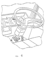
- Fig. 6 is a perspective view of the steering wheel and switches of the embodiment of this invention.
- Fig. 7 is a circuit diagram of the DC power source of the embodiment of the invention.
- Fig. 8 is a block diagram of another structure of the DC power source of another embodiment of this invention.
- Fig. 9 shows invertor output voltage and braking torque corresponding to revolving speed in the embodiment of this invention.
- Fig. 10 is a block diagram for the structure of the DC power source of the embodiment of this invention.
- Fig. 11 shows invertor output voltage, braking torque, duty ratio and substantial resistance value corresponding to revolving speed in the embodiment of this invention.
- Fig. 12 shows value of the resistance and duty ratio corresponding to temperature of the resistor, and also shows substantial value of the resistance corresponding to duty ratio.
- Fig. 13 shows value of the resistance, dissipation power and generated voltage corresponding to temperature of the resistance.
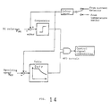
- Fig. 14 is a control model chart of a switching controller on the embodiment of this invention.
- Fig. 15 is a flow chart for the sequence of control in the control mode in the embodiment of this invention.
- Fig. 16 is a flow chart for the sequence of control in a running mode of the embodiment of this invention.
- Fig. 17 is a flow chart for the sequence of control in an auxiliary driving mode of the embodiment of this invention.
- Fig. 18 is a flow chart for the sequence of control in a starting mode of the embodiment of this invention.
- Fig. 19 is a structural view wherein another embodiment of this invention is mounted on the front side of the internal combustion engine.
- Fig. 20 is a structural view wherein another embodiment of this invention is mounted on the rear side of the transmission.
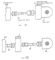
- Fig. 21 is a structural view wherein another embodiment of this invention is mounted at the inlet part of the rear axle.
- Fig. 22 is a structural view wherein another embodiment of this invention is mounted on the propeller shaft between the transmission and the rear axle.
- the reference numeral 1 denotes the internal combustion engine
- 2 the squirrel-cage polyphase induction machine
- 3 the rechargeable battery circuit
- 4 the invertor
- 5 the invertor controller
- 6 the rotary sensor
- 7 the capacitor
- 11 and 11' resistors
- 12 the semiconductor switching circuit
- 12' the switching circuit
- 13 the detector
- 14 and 14' switching controllers
- 15 the electric current detector
- Fig. 1 is a block diagram for the electric structure of the embodiment of this invention.
- Fig. 2 is a schematic view showing the mounting position of the squirrel-cage polyphase induction machine to be used in the embodiment.
- Fig. 3 is a view for the mechanical structure of the squirrel-cage type polyphase induction machine partially exploded on a plane parallel to the center of the engine crank shaft.
- Fig. 4 is a view showing the mechanical structure the section along the arrow IV-IV in Fig. 3.
- a rotor of the induction machine is engaged with the flywheel, while a stator is fixed to the flywheel housing.
- this rotary electric induction machine is a squirrel-cage polyphase induction machine
- the structure of the rotor is very simple and has no brushes.
- the gap between the rotor and the stator of the induction machine of this invention is larger, so the magnetic reluctance between the rotor and the stator will not affect significantly the braking performance.
- the manufacture precision for the gap between the rotor and stator is not as stringent as that of inductor-type power generators.
- the electric construction of this embodiment system is now described in reference to Fig. 1.
- the system comprises: a squirrel-cage polyphase induction machine 2, whose rotor is directly connected to the internal combustion engine 1, a rechargeable battery 3, an invertor 4 which converts the DC voltage of the rechargeable battery 3 to AC voltage of a frequency suitable for inducing a revolving magnetic field with a revolving speed lower than speed of the axial revolution of the induction machine 2, feeds the same to the induction machine, and converts AC current from the induction machine 2 into DC current, and an invertor controller 5 which generates control signals to set the frequency and voltage of the AC side of the invertor 4.
- the invertor controller 5 includes a means to generate control instructions from the driver, in accordance with the operational conditions of the motor vehicle.
- a rotary sensor 6 is provided on the squirrel-cage induction machine 2. Signals from the sensor 6 are fed to the invertor controller 5, and information on the charging state of the rechargeable battery is fed from the battery 3, as an input.
- a capacitor 7 and a semiconductor switching circuit 12 are connected to the output of the invertor and a resistor 11 is connected thereto, via the semiconductor switching circuit 12.
- the resistor 11 is dissipating excessive electric energy, when electric energy too large to be recovered is generated by braking.
- a detector 13 is connected to the circuit 3 and the circuit 12 to detect the output voltage of the invertor 4, while a current detector 15 is provided at the resistor 11 to detect changes in electric current.
- the detector 15 is provided with a switching control circuit 14 which controls the semiconductor switch circuit 12 in accordance with the detected signals thereof.
- the circuit 14 is connected to the detector 13.
- the squirrel-cage polyphase induction machine 2 is mounted internally in a flywheel 200 fixed between the internal combustion engine 1 and the transmission 300. More particularly, as shown in Fig. 3 in a space defined by flywheel housings 215 and 216 of the flywheel 200 are housed a stator core 211, a stator mainly comprising a stator winding 212 inserted in a slot of the core 211 and a lead wire 213, a rotor core 221, and a rotor mainly comprising a rotor bar 222 inserted in a slot of the core 221 and a retaining ring 224 fit on an end ring 223 of the bar 222.
- the stator core 211 is engaged in the stator ring 214, and the stator ring 214 is fixed to the flywheel housings 215 and 216.
- the rotor core 221 is fixed to the outer periphery of the flywheel 225 which is driven by the crank shaft 226 of the internal combustion engine 1.
- the rotor of the induction machine 2 is driven by the crank shaft of the internal combustion engine 1 mounted on an automobile.
- the stator winding of the squirrel-cage polyphase induction machine 2 receives a voltage with a frequency suitable for inducing a revolving magnetic field of a speed lower than the revolving speed of the rotor of the induction machine 2 from the invertor 4, to which DC power is supplied from the rechargeable battery 3.
- This machine 2 converts the mechanical energy of the revolving system into electric energy which is charged in the battery 3 through the invertor 4.
- the invertor controller 5 includes a device which controls the invertor 4, the degree of control in accordance with the driving conditions of the vehicle.
- the semiconductor switching circuit 12 includes a circuit which monitors the DC terminal voltage and connects the resistor 11 automatically to both terminals of the battery 3, when the terminal voltage exceeds a predetermined level.
- Fig. 5 is an electric circuit diagram to show this embodiment in more detail.
- the squirrel-cage polyphase induction machine 2 is of three phases.
- An invertor 4 connects the rechargeable battery 3 to the squirrel-cage polyphase induction machine 2.
- the negative terminal E of the battery 3 is connected to the common potential of the motor vehicle.
- the invertor 4 includes switching elements Qa, Qb, Qc, Qd, Qe, and Qf, which are connected between the positive and negative terminals of the battery 3 and each of the three terminals of the induction machine 2. These switching elements Qa, Qb, Qc, Qd, Qe, Qf comprise of transistors and diodes which are connected in parallel but in opposite directions between the collectors and emitters of the transistors.
- the invertor 4 includes an ON-OFF control signal generator PWM which feeds control signals to the control electrode of each switching element Qa, Qb, Qc, Qd, Qe and Qf.
- the invertor 4 is for the motor vehicle and has been specially designed in order to test this invention, but the basic technology thereof is well known.
- the technology for controlling a revolving magnetic field of the squirrel-cage polyphase induction machine in accordance with the rotation of the rotor is one application of a common technique popularly used in AC elevators and cranes.
- a rotary sensor 6 is mounted on the squirrel-cage polyphase induction machine 2 or the internal combustion machine 1 to detect the revolution of the crank shaft thereof and to send electric pulse signals.
- the pulse signals sent from the rotary sensor 6 are converted to an analog signal by a digital to analog converter DA1 , which indicates revolving speed.
- the analog signal is fed to one of the input terminals of the operational amplifier AMP, and a control reference corresponding to the slip generated by the digital to analog converter DA2 is fed to another input terminal of the amplifier AMP, where these two signals are subtracted or added, depending on their polarity.
- the output from the operational amplifier AMP is given to the ON-OFF controller PWM as the control signal for the output frequency of the invertor 4.
- a negative feedback servo control loop is formed by the squirrel-cage polyphase induction machine 2, the rotary sensor 6, the digital to analog converter DA1, the operational amplifier AMP, and the invertor 4.
- the controller means has circuits illustrated in the lower left part of Fig. 5, including: a microprocessor CPU, an interface circuit IO, a torque controller Tq, switches A1 and A2 linked with a throttle pedal of the vehicle, where switch A1 opens and switch A2 closes when the throttle pedal is pressed, switches N1 and N2, both of which open at the neutral position of the transmission, switches CL1 and CL2 which are linked with the clutch pedal, both open when the clutch pedal is pressed, the first switch S1 which is manipulated by the driver, the second switch S2 which is manipulated by the driver, switch KS linked with a start key switch of the internal combustion engine 1 and a digital to analog converter DA2.
- the switch S3 is a conventional exhaust brake switch which is connected to the exhaust brake circuit Ex.
- the first switch S1 is for instructing auxiliary acceleration
- the second switch S2 is for instructing electric braking to perform.
- these switches S1 and S2 are designed to be operated by a lever L which is mounted on the steering column as shown in Fig. 6.
- the lever L When the lever L is positioned at OFF, both switches S1 and S2 are open, and when it is moved to the upper position for acceleration, the switch S1 is closed.
- Four positions are marked at the lower position for braking, and plural contacts shown in switch S2 of Fig 5 are closed in accordance with the selected position of lever L. By using the four braking positions, the driver can select the degree of electric braking power.
- the degree of acceleration is determined by the position of the throttle pedal.
- the data on the position of the pedal is fed to a terminal T1 in Fig. 5 which sends it to the torque controller Tq, which gives control data to the interface IO.
- the interface IO also receives the output from the temperature sensor H mounted on the resistor 11 as an input.
- This experimental system embodying the aforementioned mechanism, has achieved a braking force as high as 100 HP, and a driving force of several tens of HP, where the driving force is depending on the characteristics of the rechargeable battery.
- This experimental result verifies utility of the system sufficiently.
- the rotor of the squirrel-cage polyphase induction machine 2 is attached on the flywheel of the internal combustion engine 1.
- the diameter of the flywheel housing is about 700 mm.
- the large components among these parts of the control system for the above embodiment in Fig. 5 are the invertor 4 and the rechargeable battery 3. It is recognized that a conventional battery for common automobiles or a slightly larger battery can be selected for the rechargeable battery 3.
- the invertor 4 has voluminous switch elements Qa, Qb, Qc, Qd, Qe, and Qf, total volume of the invertor of the test system is about 80 liters, which may generate braking force of about 150 HP.
- the size was small enough to be mounted on the underside of the body of a medium-sized truck. The volume can be reduced through the future development efforts.
- the invertor 4 comprises stationary electric parts without movable elements, for example switch elements Qa, Qb, Cc, Qd, Qe, and Qf which may be able to be installed in different locations of the vehicle. It is thereby possible to design practical forms for various types of motor vehicles.
- the driving performance of the system is similar to the driving of a vehicle with a conventional exhaust braking system and it is verified that a useful driving performance is sufficiently attained.
- the rotor means is very simple in structure, and it is durable, light, and does not have any frictional parts such as brushes.
- the gap between the rotor and the stator in the system has been set at about twice the distance as the conventional inductor type. It revealed that the trial system with the large gap does not present any particular problem, and that an even wider gap may be possible. It is, therefore, recognized that this invention requires less stringent manufacturing precision which is therefore highly advantageous for mass production.
- the squirrel-cage type structure generates almost no magnetic noise from the rotor, and that the noise of the stator is remarkably less than that of conventional inductor type retarders.
- a squirrel-cage induction machine of three phases is employed in the above embodiments, it may be possible to employ multiphase type machines of larger number of phases. By increasing the number of phases the electric current for one phase can be reduced. This is more advantageous for smaller motor vehicles, where parts of the invertor are distributed within different spaces of the vehicle.
- the invertor controller 5 issues control signals for generating the revolving speed of the magnetic field which is less than the mechanical revolving speed of the rotor of the induction machine 2 detected by the sensor 6.
- the squirrel-cage polyphase induction machine 2 acts as a power generator, and the electric energy generated is converted into DC energy by the invertor 4 and the D C energy is fed to the rechargeable battery 3.
- the terminal voltage of the battery 3 increases to exceed the predetermined level, and the semiconductor switching circuit 12 is closed to connect the terminal of the battery 3 with the resistor 11.
- the invertor controller 5 When driving force is required for the rotary system, the invertor controller 5 issues control signals for generating the revolving speed of the magnetic field which is higher than the mechanical revolving speed of the rotor of the induction machine 2 detected by the sensor 6. At this time, DC current is taken out from the rechargeable battery 3. DC current is converted to polyphase AC current corresponding to the revolving magnetic field by the invertor 4, and is fed to the squirrel-cage polyphase induction machine 2.
- the ratio of the difference against the revolving speed of the rotary magnetic field, i.e. the slip of the squirrel-cage polyphase induction machine 2 is restricted within ⁇ 10%.
- the invertor 4 is fed with control signals from the invertor controller 5 for inducing a revolving magnetic field corresponding to the revolution of the rotor on the stator of the induction machine 2.
- the invertor controller 5 is fed with revolution data from the sensor 6 and with the data on the charging state of the battery 3.
- the invertor controller 5 includes a microprocessor.
- the invertor controller 5 includes a means to take in operation control signals which are changed by the manipulation of the driver.
- the invertor 4 can feed energy from DC terminals to AC terminals, as well as the energy from AC terminals to DC terminals.
- the invertor can further operate the squirrel-cage polyphase induction machine 2 as a polyphase motor by controlling the revolving speed of the revolving magnetic field, depending on the control signal from the invertor controller 5, and the induction machine 2 gives driving force to the rotary shaft.
- the induction machine 2 works as an auxiliary engine device for the internal combustion engine 1.
- the electric energy charged at the battery 3 is used.
- the charging current for a rechargeable battery of a motor vehicle is fed from a generator driven by the internal combustion engine, and charging is continued as long as the internal combustion engine rotates.
- the charging current to the battery is controlled to attain a fully charged state to the rated capacity in as short a time as possible.
- the energy generated for braking is recycled as electric energy and is used as an auxiliary power for running the vehicle as above, it can not effectively recover braking energy to improve fuel efficiency if the rechargeable battery is constantly maintained at a fully charged state to the rated capacity. If the target capacity for charging is set at a very low level to the rated capacity, on the other hand, the charged energy is exhausted when the starter motor is repeatedly used at a certain driving condition.
- the target capacity for charging the rechargeable battery is selected to be smaller than the rated capacity at normal conditions.
- the target capacity must depend on various conditions, such as braking performance, driving conditions, the rated charging capacity of a rechargeable battery, and temperature.
- the target capacity may be 50 to 70% of the rated capacity.
- the system issues an alarm urging the driver to use the auxiliary driving force. Then the electric energy is fed to the squirrel-cage polyphase induction machine 2 by the driver's operation, and its effective use is attained.
- this embodiment employs a method to monitor the terminal voltage of the battery for discrimination.
- the method is not precise but useful.
- the system may employ methods to either monitor the density of battery liquid, or to measure and calculate the electric charge and discharge of the battery.
- the system may employ a method for reducing fuel consumption of the internal combustion engine by warning the driver that the charged electricity in the battery is excessive and urging him to use the auxiliary driving force.
- Another method that can be employed is to incorporate a microprocessor in the invertor controller 5, which receives information that the charged energy is exceeding the preset target level, and which automatically controls the squirrel-cage polyphase induction machine 2 to operate as a motor, even during normal driving, in accordance with the pressed value of the throttle pedal.
- a rechargeable battery 3 As shown in Fig. 5, a rechargeable battery 3, the serial circuit of a resistor 11, and a semiconductor switching circuit 12 are connected to the DC terminal E1 and E2 of the invertor 4.
- a controller CT1 is connected to the control electrode of the semiconductor switching circuit 12.
- the controller CT1 is independent of the controlling system, including the aforementioned microprocessor CPU1, so that when the voltage between the terminals E1 and E2 exceeds the target level, the semiconductor switching circuit 12 is automatically actuated.
- a temperature sensor H is provided on the resistor 11 which is connected in serial manner to the semiconductor switching circuit 12, and the output from the sensor H is fed to the interface circuit IO. When the temperature of the resistor 11 exceeds the preset value, the slip of the revolving magnetic field may be decreased thereby reducing braking torque.
- Operational voltage between the terminal E1 and E2 is in the range of 300 - 600V.
- a circuit shown in Fig.7 is employed in order to match the voltage above to the voltage of the battery at 24V, the conventional battery voltage of a large motor vehicle.
- Terminals E1 and E2 in Fig. 7 are connected to the terminals E1 and E2 in Fig. 5.
- the capacitor C1 is connected to terminals E1 and E2.
- the rated voltage of the battery B is 24 V.
- the capacitor C2 is connected to the battery B.
- serial circuit of a reactor L and a diode D2 for countercurrent prevention are inserted.
- a collector/emitter circuit of the transistor Q2 is connected between the connection of the reactor L with the diode D2 and the terminal E2.
- a collector/emitter circuit of the transistor Q3 is connected in parallel to the diode D2.
- this circuit includes two comparators CP1 and CP2 and a controller CT2 to feed a controlling pulse to the transistors Q2 and Q3 shown as Dr and Br respectively.
- the transistor Q2 is used when the induction machine 2 works as a motor.
- the transistor Q3 is used when the induction machine 2 works as a generator.
- the controller CT2 receives as input the operation data of the first and second switches S1 and S2, which are described in relation to Fig. 5.
- the first switch S1 and the second switch S2 are manipulated by the driver, and the first switch S1 is closed for auxiliary acceleration while the second switch S2 is closed for electric braking.
- the controller CT2 selects the terminal Dr.
- the voltage of the battery B is applied for a short period of time on the reactor L, which is followed by a generation of high voltage.
- the sum of the voltage at the two terminals of the reactor L and the terminal voltage of the battery 3 is supplied to the capacitor C1 through the diode D2.
- the terminal voltage of the capacitor C1 becomes the DC power source voltage for the squirrel-cage polyphase induction machine 2, when it acts as a motor.
- the DC power source voltage is compared with the reference voltage Er2 by a comparator CP2, and the pulse width and repetition period thereof are adjusted to keep the voltage in the preset range.
- the controller CT2 selects the terminal Br. At this time, periodic pulses are fed to the control input terminal Br of the transistor Q3 to intermittently actuate the transistor Q3.
- This intermittent operation forms an intermittently closed loop between the capacitor C1(terminals E1 and E2), capacitor C2, the reactor L, and the transistor Q3 so as to store energy in the reactor L.
- energy in the reactor L increases and the terminal voltage of the reactor L becomes larger than the terminal voltage of the battery B
- a closed loop in the opposite direction of current is formed between the reactor L, the battery B, and the diode D3 to allow passage of electric current and to charge the battery B.
- the terminal voltage of the battery B and the terminal voltage of the capacitor C2 are compared with the reference voltage Er1 by the comparator CP1, and the pulse width and repetition period thereof are adjusted to keep the voltage in the preset range.
- the braking mode (1)a which is the mode where the vehicle is braked, a large amount of energy is generated by the squirrel-cage polyphase induction machine 2, part of which is recovered by the battery B, but most of which is dissipated by the resistor 11.
- the slip of the revolving magnetic field to be fed to the induction machine 2 is controlled to remain negative at a high level.
- This mode is determined by the driver closing the second switch S2. It is controlled to generate an increasingly larger braking torque by closing the contacts of the second switch S2 in sequential steps.
- the running mode (1)b is the mode for normal driving of the car where a relatively small amount of energy is generated by the squirrel-cage polyphase induction machine 2, to be gradually but continuously charged in the rechargeable battery B.
- the slip of the revolving magnetic field to be given to the induction machine 2 is controlled to be negative and low.
- the control mode is automatically shifted to this mode.
- the Driving mode (2) can be further divided into
- the revolving force is fed from the induction machine 2 instead of conventional DC starter motor.
- a slow revolving magnetic field such as 200 rpm is given to the induction machine 2. This eliminates the need for a starter motor, pinion gears, magnet switches, and other facilities, which are normally required for starting.
- the system gives revolving magnetic field a speed slower than the actual revolving speed of the rotor, or a negative slip to the induction machine 2.
- the induction machine 2 works as a generator, and the electric current for the rotary magnetic field is fed through the transistor parts of the switching elements Qa, Qb, Qc, Qd, Qe and Qf.
- the electric energy generated by the induction machine 2 is recycled to the battery 3 through the diode parts of switching elements Qa, Qb, Qc, Qd, Qe and Qf.
- the terminal voltage of the battery 3 is increased and the semiconductor switching circuit 12 is closed to dissipate the energy from the resistor 11 as thermal energy.
- the slip of the rotary magnetic field is controlled through the output from the temperature sensor H, to be less and braking force is reduced, in order to keep the system within a safe working range.
- the induction machine 2 is given a positive slip whereby revolving speed of the rotary magnetic field is greater than that of the rotor of the induction machine 2. This makes the induction machine 2 work as a motor by giving revolving force to the crank shaft of the engine 1.
- Fig. 8 is a block diagram which shows an embodiment of a circuit which detects the revolving speed of the crank shaft and controls the resistance value of the resistor 11.
- the circuit may be constructed by: inserting a resistor 11' with ON-OFF switches SW1, SW2, and SW3 which can select resistance value of R1 , R2 , and R3 between terminals E1 and E2 of the invertor 4, connecting a switch controller 14' which controls the ON-OFF switches SW1, SW2 and SW3, and connecting a detector 13 which detects the output voltage and gives a signal to the controller 14'.
- controllable range can be expanded by switching the ON-OFF switches SW1, SW2, and SW3 in accordance with the signals detected relating to revolving speed.
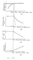
- Figs. 9(a) and 9(b) show the output voltage and braking torque of the invertor in relation to revolving speed.
- the resistance is increased as R3, R2 and R1 while the revolving speed increases.
- the invertor output voltage can be maintained at a substantially constant value.
- braking torque slightly lowers as the revolving speed increases, the braking torque remains at a sufficiently practical level. It has been thus found that the resistance should be changed in order to carry out braking over a wide range.
- Fig. 10 is a block diagram which shows the structure of this circuit wherein terminals E1 and E2 are connected to the terminals E1 and E2 of Fig. 5.
- the circuit comprises: a capacitor 7 connected to the terminals E1 and E2 of the invertor 4, a low value resistor 11 to which electric current generated in the stator winding of the induction machine 2 is fed through the invertor 4, a semiconductor switch 12 connected between the resistor 11 and the invertor 4 for switching the circuit, a detector 13 which detects the voltage applied thereon from the invertor 4, a switch controller 14 which controls the substantial value of the resistor 11 to increase as the output detected by the circuit 13 and the rotary sensor 6 increases, and an electric current detector 15 provided on the resistor 11 which detects the changes in electric current and outputs detection signals to the switch controller 14.
- the rechargeable battery circuit 3 includes a rechargeable battery 31, a reactor 32, a semiconductor switch 33, and a controller 34.
- the detector 13 detects the voltage and send a signal to the switch controller 14.
- the switch controller 14 controls the resistor 11 by giving ON-OFF control signals to the semiconductor switching circuit 12 in order to increase the substantial value of the resistor 11.
- Figs. 11(a), 11(b), 11(c) and 11(d) show the relationship between revolving speed of the crank shaft of the engine 1 and DC output voltage, braking torque, duty ratio, and the substantial resistance of the invertor 4.
- the detector 15 detects elevation in temperature in the resistor 11, in terms of electric current, and sends the detection output to a switching controller 14.
- the switching controller 14 gives ON-OFF control signals with changing a duty ratio to the semiconductor switching circuit 12, so that substantial value of the resistor 11 can be kept low value.
- Fig. 12 (a) shows the relation of temperature to resistance
- Fig. 12 (b) the relation of temperature to duty ratio
- Fig. 12(c) the relation of duty ratio to substantial resistance.
- the duty ratio is controlled to increase with the rise in temperature as shown in Fig. 12(b). Substantial resistance decreases with the increase in duty ratio as shown in Fig. 12(c).
- Increase in temperature of the resistor 11 is detected as electric signals by the detector 15, and these signals are sent to the switching controller 14 so that an ON-OFF control signal is transmitted to the semiconductor switching controller 12 for increasing duty ratio, and resistance is made lower substantially as shown by the solid line in Fig. 12(a). This enables the dissipation of a large amount of electric power over a longer time so as to maintain braking torque.
- the invertor 4 may also be controlled with electric signals detected increase in temperature of the resistor 11, as following manners.
- Fig. 1 when the induction machine 2 act as a generator, AC current is generated on the stator winding of the induction machine. It is converted by the invertor 4 into DC current and is applied to the resistor 11 for dissipating electric power. When dissipation of electric power is continued for a long time, the temperature of the resistor 11 rises.
- the detector 15 detects the increase in temperature on the resistor 11 from its electric current, and transmits the detection output to the invertor controller 5.
- the invertor controller 5 may control the pulse width in order to increase output voltage of the invertor.
- the invertor controller 5 may also control the revolving speed of the magnetic fields of the induction machine in order to increase output voltage of the invertor.
- Figs. 13(a), 13(b), and 13(c) show the relation of temperature increase to resistance (R), dissipated power (P), and generated voltage (V).
- control of the resistance of the resistor 11 involves several factors. It is therefore necessary for the switching controller 14, shown in Fig. 10, to be able to optimally control resistance regarding a number of factors.
- a control model is illustrated in Fig. 14 for an embodiment of the switching controller 14.
- the switching controller 14 is in practice realized by a programmed controller as shown in Fig 14. In the model, DC input voltage Vdc is monitored by a comparator in the main controlling system, and when voltage exceeds the predetermined level (corresponding to the above mentioned Vc), an ON-OFF control signal is issued to make DC voltage Vdc agree with Vc.
- the first auxiliary control system is provided, where input revolving speed is monitored and compared with a stored table, and when the revolving speed reaches the predetermined level (corresponding to the above Nc2 ), an ON-OFF control signal is issued.
- the main controlling system is connected with the auxiliary controlling system by an AND circuit.
- the factor is controlled by issuing control signals with either the input from the temperature sensor (not shown) provided on the resistor 11 or with the detected current of the resistor 11, or, alternatively, by the method of correcting the control output from the above first auxiliary controlling system.
- Fig. 15 shows a flow chart in a braking mode
- Fig. 16 in a running mode
- Fig. 17 in an auxiliary driving mode
- Fig. 18 in a starting mode.
- control by the temperature sensor or by the electric current sensor, which compensates changes in resistance is omitted.
- this invention can carry out coordinated control by detecting the revolving speed of the main shaft of the internal combustion engine 1 and the output voltage from the invertor 4, and by changing the duty ratio of ON-OFF control signals to be fed to the semiconductor switching circuit 12 based on the detection output, so that braking torque may be maintained over a wide range.
- this invention detects the electric current corresponding to temperature change, and changes the duty ratio of the ON-OFF control signals to be fed to the semiconductor switching circuit 12, so that controls over number of factors are harmonized and braking torque may be maintained over a long period of time.
- the aforementioned embodiment of this invention has a structure wherein the rotor of the squirrel-cage polyphase induction machine 2 is mounted on the flywheel which is engaged with the crank shaft of the internal combustion engine, and a stator is mounted on the inside of the flywheel housing; however, the mounting position the induction machine 2 is not limited to the flywheel or to the flywheel housing.
- Fig. 19 shows a structure wherein the squirrel-cage polyphase induction machine 2 is mounted on the front end of an internal combustion engine. Although this structure is inferior, in that it cannot be mounted on a conventional vehicle chassis, it can achieve better balance in the crank shaft, and a crank torsional dumper can be removed.
- Fig. 20 shows a structure wherein the squirrel-cage polyphase induction machine 2 is mounted on the rear portion of the transmission 300.
- the induction machine 2 is not integral with the internal combustion engine 1 but may be separated by a clutch (not shown) and the transmission 300.
- This structure allows the application of braking even if separated from the internal combustion engine 1 because the structure is made integral with the rotation of axle.
- Fig. 21 shows a structure wherein the squirrel-cage polyphase induction machine 2 is mounted on the entrance of the rear axle 40. Like the structure shown in Fig. 20, this structure may be separated by a clutch (not shown) or the transmission 300, and is therefore not integral with the internal combustion engine 1.
- the attachment structure on the internal combustion engine is identical to the one used for conventional machines, need for without changes or additions, for except in a change in the length of the drive shaft.
- Fig. 22 shows another structure wherein the squirrel-cage polyphase induction machine 2 is mounted on the propeller shaft 30 between the transmission 300 and the rear axle 40. Like those examples shown in Figs. 20 and 21, it may be separated by a clutch (not shown) or the transmission 300, and is not integral with the internal combustion engine 1. It has an improved space factor and has the capacity to use a large rotary machine.
- each embodiment may achieve the similar effect, as stated in the foregoing statement, because structures and operations are the same.
- this mechanism uses a squirrel-cage polyphase inductor, compared with retarder of an eddy-current type or an inductor-type power generator in prior art, this mechanism is smaller and more durable, less noise and less susceptible to magnetic leakage, to thereby providing a stronger braking force.
- the mechanism allows a wider gap between its stator core and rotor core, the manufacturing precision can be less precise. This mechanism is therefore highly suitable for the mass-production of electric braking devices. This mechanism is applicable to various motor vehicles including large, medium and small automobiles.
- This mechanism is equipped with an invertor means, which can sufficiently adjust frequencies to output a frequency corresponding to the revolving speed of the rotary magnetic field of the squirrel-cage polyphase inductor, and with a resistor which can dissipate transitional excessive electric energy as thermal energy when the braking force is applied, thereby maintaining a high braking force by dissipating excessive electric energy generated by braking.
- the mechanism of this invention can be operated as a driving means at a low cost and thereby effectively recycle the energy which is inevitably generated by braking. This saves fuel.
- this invention can provide a practical application which can generate powerful braking torque effectively over a long period of time and over a wide range of revolving speed.
Landscapes
- Engineering & Computer Science (AREA)
- Mechanical Engineering (AREA)
- Transportation (AREA)
- Power Engineering (AREA)
- Chemical & Material Sciences (AREA)
- Combustion & Propulsion (AREA)
- General Engineering & Computer Science (AREA)
- Electric Propulsion And Braking For Vehicles (AREA)
Abstract
Description
- This invention relates to an electric braking and auxiliary engine mechanism which performs braking and auxiliary acceleration for motor vehicles and more particularly, to an electric braking and auxiliary engine mechanism which includes a rotary machine directly coupled to the crank shaft of an internal combustion engine which drives the axle of the vehicle.
- The progress of internal combustion engines, especially improvements in supercharging technology, along with development of thermally resistant materials, have successfully realized an internal combustion engine of small stroke volume with high output power. As the capacity of an internal combustion engine becomes smaller, however, the effect of an exhaust retarder or an engine brake is reduced in correspondence with to its stroke volume, necessitating the concurrent use of a retarder. More specifically, an auxiliary brake system is required in addition to the friction brake equipment mounted on wheels, to offset acceleration caused when motor vehicles go downhill, or to reduce the speed to a predetermined level in the initial stage of braking at high speed. There has been provided a retarder, of an eddy current system type of a power generator with an inductor-type structure, directly coupled with the rotor shaft of the internal combustion engine. Although the retarder of an eddy current system is sturdy enough to withstand the outside force caused by the irregular vibration of wheels due to rough roads, the system cannot regenerate useful energy as it converts all of the mechanical energy to be consumed for braking into thermal energy and dissipates it into the atmosphere. This goes against the recent trend of improving fuel consumption , and a device with a large thermal capacity mounted on a motor vehicle for thermal radiation inconveniently increases the size of the system.
- It has been proved that the direct coupling of an inductor-type alternator with the crank shaft of an internal combustion engine is effective as an auxiliary retarder. It has also been proved that in this system, mechanical energy consumed for braking can be converted into electric energy, and that electric energy is recovered in a rechargeable battery which may be used for a starter or other facilities mounted on the vehicle. A generator of this type is, however, defective in that the gap between the stator and the rotor of the generator must be as small as possible, in order to prevent magnetic leakage which reduces efficiency, and that the manufacturing precision of the rotor and the stator must be improved to an extensive degree. This will require considerable working expense in mass production.
- The machine would be able to provide extra operational modes for drivers to improve driving performance, when the driving means for start/acceleration and climbing/running support are used in addition to the main driving means.
- Inventors have conducted experiments using a squirrel-cage polyphase induction machine as above, and have found that a large braking force is obtained, that electric energy, generated by braking, can be recovered to a large extent in a rechargeable battery, and that the rechargeable battery can be used effectively as the electric power source for auxiliary power.
- Inventors have carried out various experiments in order to grasp the relation between the revolving speed of the rotor and the braking torque given to the crank shaft. They have noticed a phenomenon in which no braking torque is generated when the revolving speed of the rotor is at a certain high value, and when low resistance value of a shunt resistor is connected to the electric output of the machine in order to attain large braking torque. They have carried out their experiments by varying the resistance value of the resistor and the revolving speed, in order to find out the reason. They have learned that braking torque is reduced rapidly when the output is terminated by a resistor of small value, and when the revolving speed of the shaft is low, and that as the resistance value increases, the range for generating normal braking torque expands with the higher revolving speed of the shaft. However, large braking torque cannot be attained with a high value of resistance because its dissipated energy is low.
- Inventors have considered the following: The squirrel-cage polyphase induction machine and the invertor may be regarded as one integral DC power source. The power generated by the DC power source is proportional to the revolving speed of the squirrel-cage polyphase induction machine, and the output voltage of the DC power source is also proportional to the revolving speed . The power dissipated by the resistor, which is the load of the power source, however, is proportional to square of the output terminal voltage. Accordingly, when revolving speed increases and when the output voltage increases, dissipated power is exceeding generated power. This means that the squirrel-cage polyphase induction machine of this state is not working as a power generator, and that the machine rapidly loses braking torque.
- Inventors have also observed that when a large electric current is continuously supplied to the resistor in order to generate a large braking torque continuously, the braking torque becomes lower with the passage of time. This is because the resistor is heated by the current and because value of the resistor increases with the temperature. This means the dissipated electric energy becomes smaller. In order to avoid this phenomenon, a resistor with a small resistance value might be selected, but it should be avoided, because the small resistance value would make the current increases and the stator winding of the machine would be heated when a large braking torque is generated.
- It is known, on the other hand, that a technology has been disclosed by Volkswagen AG of West Germany in OS No. 2943554 (Patent Disclosure of West Germany) and the United States Patent No. 4,533,011, wherein an electric machine is used as a generator for the brake, or as a motor of the auxiliary driving device.
- In the Patent Disclosure above, it is disclosed that an electric machine is connected to the crank shaft, and that the electric machine is used as an auxiliary motor device. It is also disclosed that the machine may be driven by the internal combustion engine as a power generator to charge the battery, the power of which can be used for the auxiliary motor. It must be noticed, however, that a second clutch is provided in the disclosed device, for coupling the rotor shaft of the squirrel-cage induction machine to the axle of the motor vehicle, and for separating it from the crank shaft of the internal combustion engine. When the second clutch is opened, the motor vehicle may be driven as an electric vehicle with the auxiliary power alone to achieve a noiseless engine without air-polluting exhaust gas. It is not mentioned, however, that the machine may be used as a retarder to help the engine brakes. Moreover, they do not mention anything about the use of a resistor with a low value for energy dissipation.
- JP-A-61-154462 discloses an electric motor-generator mounted on the crankshaft of an internal combustion engine. Separate motor and generator coils are provided on the rotor, connected to a commutator and slip rings respectively. A single coil is carried by the stator.
- JP-U-53-49608 describes an inverter circuit for an electric machine. The circuit includes switching elements that are controlled according to the rotating speed of the electric machine.
- DE-A-24 36 546 describes an auxiliary drive mechanism for a vehicle. Two electric machines are coupled to drive shafts of the vehicle to provide additional torque at low speeds. Energy recovered upon braking the vehicle is stored in a flywheel.
- CH-A-492 336 describes an electric braking method for an electric motor. The energy generated by braking the motor is dissipated in resistors.
- The primary object of this invention is to provide an auxiliary engine system for motor vehicles which is mechanically durable, generates less noise, achieves stronger braking, and is suitable for mass-production.
- The second object of this invention is to provide an auxiliary engine system for motor vehicles which is provided with an invertor means with a sufficient frequency range to output frequencies corresponding to variations in the revolving speed of the magnetic field of the squirrel-cage polyphase induction machine, so that it may be operated as an auxiliary driving means, at a lower cost, without occupying additional space on the motor vehicle.
- The third object of this invention is to provide an auxiliary engine system for motor vehicles which can maintain high braking torque by dissipating the electric energy continuously at the resistor.
- The fourth object of the invention is to provide an auxiliary engine system for motor vehicles which can effectively recycle electric energy generated by braking to a rechargeable battery, which may be used as an auxiliary power source.
- The fifth object of the invention is to provide an auxiliary engine system for motor vehicles which can effectively generate a large braking torque for a long period of time over a wide range of revolving speeds of the crank shaft of an internal combustion engine.
- According to the present invention, there is provided an electric braking and auxiliary engine mechanism for a motor vehicle including a rotary electric machine coupled to the crank shaft of an internal combustion engine for driving the axle of the vehicle, which is characterized in that said crank shaft and the rotary shaft of said rotary machine are directly coupled, that said rotary machine is a squirrel-cage polyphase induction machine, that an electric means is provided to induce a revolving magnetic field to the squirrel-cage polyphase induction machine, and that said mechanism includes a DC power source including a rechargeable battery, and an invertor which gives a revolving magnetic field to said squirrel-cage polyphase induction machine with the electric current supplied from said DC power source, said invertor having a frequency adjusting range to allow outputs of frequency corresponding to the revolving speed of the rotary magnetic field higher than that of said squirrel-cage polyphase induction machine and of a frequency corresponding to the revolving speed of the rotary magnetic field lower than that of said revolving speed but in the same direction.
- This system is preferable in its structure, as the a rotor of said squirrel-cage polyphase induction machine is mounted on a fly-wheel engaged with the crank shaft of an internal combustion engine, while a stator thereof is mounted on inside of the fly-wheel housing.
- It becomes possible to perform braking suitable to the running conditions of motor vehicles by directly coupling the rotor of the squirrel-cage polyphase induction machine with the crankshaft of the combustion engine as mentioned above, and to control electrically the revolving speed of magnetic field at the stator of the squirrel-cage polyphase induction machine. More specifically, the squirrel-cage polyphase induction machine may be operated as a power generator by making the revolving speed of the magnetic field lower than the mechanical revolving speed of the rotor, thereby giving a braking torque to the motor vehicle. The squirrel-cage polyphase induction machine may be used as a driving motor by making the revolving speed of the magnetic field higher than the mechanical revolving speed of the rotor so as to give auxiliary driving force to the crank shaft of the internal combustion engine.
- As it is impossible to predict the driving conditions for the motor vehicle which require braking, the necessity arises always unexpectedly. It is, therefore, preferably for a rechargeable battery to be charged initially with less than the rated chargeable capacity, and the battery is available to be recharged with electric energy, with high efficiency, when such electric energy is generated for electric braking. The charged energy can be used as an auxiliary driving force to save fuel consumption by the internal combustion engine by that amount.
- Preferably, the invertor means according to this invention is connected between the phase terminals of the squirrel-cage polyphase induction machine and the two terminals of the DC power source, and is provided with switching elements each of which includes a parallel circuit of transistors and diodes.
- It may also comprise a rotary sensor which detects the revolving speed of the squirrel-cage polyphase induction machine as an electric signal, a control means which generates control reference during the time the vehicle is being driven, an adder which issues control signals to feed the sum to said switching elements by adding the control reference to the revolutional speed data, a serial circuit with a switching circuit, and a resistor with a small resistance connected to both terminals of said DC power source.
- Preferably the control means to give the reference for control includes: one switch which is manipulated by the driver of the car to instruct auxiliary acceleration, another switch which is manipulated by the driver to instruct auxiliary braking, and a programed control circuit which generates the control reference to give a different slip in positive or negative values to the squirrel-cage polyphase induction machine, with the manipulation of said two switches. It is preferable that the control means to give the reference include a circuit which inputs the manipulation information of the starter key switch, of the internal combustion engine, and also that the programed control circuit include a means to generate the reference so as to induce a revolving magnetic field, suitable to start the internal combustion engine, the squirrel-cage polyphase induction machine based on the above information.
- The DC power source may include a rechargeable battery whose rated terminal voltage is lower than the rated terminal voltage of the DC power source, with a step-up chopper and a step-down chopper of a reactor type connected to the rechargeable battery. The switching circuit may include a circuit which automatically closes when the terminal voltage of the DC power source reaches a predetermined voltage higher than the rated terminal voltage thereof.
- The mechanism of this invention thus constructed may be used as a braking system, when the revolving speed of the revolving magnetic field is controlled to give a negative slip in respect to the revolving speed of the rotor operating it as a power generator, and may be used as an auxiliary motor, when it is controlled to give a positive slip in respect to the revolving speed of the rotor.
- As switching elements of a complex type, which include a parallel circuit of transistors and diodes, are installed in the invertor circuit, DC electric current can be taken out through said elements when the mechanism is used as a generator, and the electric current for the revolving magnetic field can be supplied from the DC power source, through said elements, when it is used as a motor. The revolving speed information of the squirrel-cage polyphase induction machine is detected in the form of electric signals, with which negative feedback servo control is performed in order to give the desired revolving magnetic field to the induction machine via the control of the invertor circuit. This enables control with higher stability and higher precision. The control reference for said negative feedback servo control is generated in accordance with the driving operation so as to match the conventional driving operation of the motor vehicle .
- When the squirrel-cage polyphase induction machine is used as a generator, the energy generated may be recycled for the DC power source. However, it is impossible to recover all of the electric energy generated from braking as the braking operation is needed at any time, depending on the driving conditions, and the braking torque generally fluctuates in a wide range. A dissipating resistor is therefore provided to deal with the situation where the braking energy is too excessive to be recovered. The resistor is connected to the electric output of the machine with a switching circuit so as to dissipate the excessive electric energy, which is dissipated as thermal energy when providing large braking torque in a short period.
- The dissipating resistor is adapted to automatically connected to the electric output when the terminal voltage of the DC power source reaches a predetermined voltage (e.g. 120%) which is larger than the rated terminal voltage thereof, so that control of the dissipation of braking energy of the resistor is independent of said negative feedback servo control.
- When two switches mentioned above are provided for manipulation by the driver, proper driving operation may be performed by feeding different slips in positive and negative directions to the squirrel-cage polyphase induction machine, in accordance with the driver's manipulation.
- This mechanism may be provided with a circuit which receives input information from the start key switch of the internal combustion engine, and with a program circuit which generates the control reference for giving a revolving magnetic field, of an extremely low speed, suitable to the start of the internal combustion engine, to the squirrel-cage polyphase induction machine corresponding to said input information from the start key switch. The squirrel-cage polyphase induction machine can be used also as a motor to start the internal combustion engine.
- The squirrel-cage polyphase induction machine and the invertor circuit may have higher output voltages to reduce output polyphase current, but the DC current conventionally mounted on motor vehicles is of a considerably low voltage. In order to match such low voltage current with the output voltage of the invertor circuit, it is preferable to provide a step-up chopper and a step-down chopper, of a reactor type, which converts the relatively low voltage of the rechargeable battery to and from the terminal voltage, on the DC side of the invertor.
- The mechanism of this invention is characterized by a detector, which detects electric signals corresponding to revolving speed of the crank shaft, and a controller which controls the substantial resistance value of the resistor to be a larger value, as the speed detected by the detector increases.
- The controller preferably includes a semiconductor switching circuit serially connected to the resistor, and a switching controller which gives periodical control signals to the semiconductor switching circuit. The switching controller preferably includes a circuit which can change the duty ratio of control signals in accordance with output of the detector, while the detector preferably includes a circuit which detects changes in the electric current passing through the resistor as electric signals corresponding to temperature of the resistor. The controller preferably is structured in a manner that only when detection output from the detector exceeds a predetermined level, the equivalent value of the resistor is controlled to increase to a larger value.
- The mechanism according to this invention preferably includes a temperature detector which detects electric signals corresponding to the temperature of the resistor mentioned above, and a controller which controls the substantial value of the resistor to be at a smaller level, when the temperature of the resistor increases in accordance with the output from the detector.
- It is preferable that the controller include a semiconductor switching circuit connected serially to the resistor, and a switching controller which gives periodic ON-OFF control signals to the semiconductor switching circuit. The switching controller includes a circuit which can vary the duty ratio of the signals in accordance to the output from said temperature detector. The temperature detector includes a circuit which detects the changes in electric current passing through the resistor in the form of electric signals corresponding to the temperature of the resistor, and the controller includes a means which can control substantial values of the resistor corresponding to the output from the detector.
- It is further preferable that this mechanism include a detector which detects electric signals in correspondence to the temperature of the resistor, and a controller which controls the revolving magnetic field in correspondence to the output from the detector, so as to increase voltage generated from the squirrel-cage polyphase induction machine. The controller may includes a means which can control the pulse width of the electric current to be fed to the squirrel-cage polyphase induction machine.
- Substantial value of the resistor should be varied in accordance with the revolving speed of the crank shaft of the internal combustion engine, in order to carry out electric braking at a high efficiency for a long time over a wide range of revolving speeds. When the revolving speed is low, resistance should be small, and as the revolving speed increases, resistance should be larger. This can be realized by changing the connecting taps of the resistor. However, the device for switching the taps of the resistor requires a number of switching circuits and resistor elements, with high thermal and current capacity. This would inconveniently increase the size and weight of the device mounted on the motor vehicle . It is therefore preferable to use a circuit comprising a resistor of low value and a semiconductor switching circuit, connected serially, so that substantial resistance value can be varied by periodically turning the semiconductor switching circuit ON and OFF to change the duty ratio thereof.
- It is also preferable to use the output from the rotary sensor as the electric signals corresponding to the revolving speed of the crank shaft. In accordance with the output, ON-OFF control signals of varying duty ratio are fed to the semiconductor switching circuit so that as the output increases, substantial value of the resistor may be controlled to be set at larger value. In this manner, matching the power generator and the load may be improved in the range where revolving speed is high and generated voltage is high. It increases braking torque and accordingly the system can be applied to an electric braking system over a wide range.
- The power dissipated P by the resistor is expressed as

when the resistance of the resistor is R and the DC voltage, of the resistor is V. When electric power is continuously dissipated for a long time on the resistor, temperature of the resistor increases and the resistance R also increases. If the resistance R is controlled to be at a smaller level in effective value, a large dissipated power can be maintained for a long time. - More particularly, the output voltage of the invertor and the electric current of the resistor are monitored, so that when the current passing through the resistor increases in proportion to voltage of the invertor, the substantial resistance value of the resistor is controlled to be increased. When electric current decreases, due to heat generated by the resistor itself, even if the voltage remains at the same level, the substantial resistance value of the resistor is controlled at lower level.
- The rise in temperature of the resistor is most simply detected by watching if electric current passing through the resistor becomes smaller so as to learn the decrease in electric current corresponding to the increase in temperature.
- Fig. 1 is a block diagram of the structure of an embodiment according to this invention.
- Fig. 2 is a schematic view showing the mounting position of the squirrel-cage polyphase induction machine used in the embodiment of this invention.
- Figs. 3 and 4 are mechanical structural views of the structure of the squirrel-cage polyphase induction machine used in the embodiment of this invention.
- Fig. 5 is an electric circuit diagram in detail of the embodiment of this invention.
- Fig. 6 is a perspective view of the steering wheel and switches of the embodiment of this invention.
- Fig. 7 is a circuit diagram of the DC power source of the embodiment of the invention.
- Fig. 8 is a block diagram of another structure of the DC power source of another embodiment of this invention.
- Fig. 9 shows invertor output voltage and braking torque corresponding to revolving speed in the embodiment of this invention.
- Fig. 10 is a block diagram for the structure of the DC power source of the embodiment of this invention.
- Fig. 11 shows invertor output voltage, braking torque, duty ratio and substantial resistance value corresponding to revolving speed in the embodiment of this invention.
- Fig. 12 shows value of the resistance and duty ratio corresponding to temperature of the resistor, and also shows substantial value of the resistance corresponding to duty ratio.
- Fig. 13 shows value of the resistance, dissipation power and generated voltage corresponding to temperature of the resistance.
- Fig. 14 is a control model chart of a switching controller on the embodiment of this invention.
- Fig. 15 is a flow chart for the sequence of control in the control mode in the embodiment of this invention.
- Fig. 16 is a flow chart for the sequence of control in a running mode of the embodiment of this invention.
- Fig. 17 is a flow chart for the sequence of control in an auxiliary driving mode of the embodiment of this invention.
- Fig. 18 is a flow chart for the sequence of control in a starting mode of the embodiment of this invention.
- Fig. 19 is a structural view wherein another embodiment of this invention is mounted on the front side of the internal combustion engine.
- Fig. 20 is a structural view wherein another embodiment of this invention is mounted on the rear side of the transmission.
- Fig. 21 is a structural view wherein another embodiment of this invention is mounted at the inlet part of the rear axle.
- Fig. 22 is a structural view wherein another embodiment of this invention is mounted on the propeller shaft between the transmission and the rear axle.
- In the figures the
reference numeral 1 denotes the internal combustion engine, 2: the squirrel-cage polyphase induction machine, 3: the rechargeable battery circuit, 4: the invertor, 5: the invertor controller ,6: the rotary sensor, 7: the capacitor, 11 and 11': resistors, 12: the semiconductor switching circuit, 12': the switching circuit, 13: the detector, 14 and 14': switching controllers, and 15: the electric current detector. - This invention will now be described referring to an embodiment shown in the attached drawings.
- Fig. 1 is a block diagram for the electric structure of the embodiment of this invention. Fig. 2 is a schematic view showing the mounting position of the squirrel-cage polyphase induction machine to be used in the embodiment. Fig. 3 is a view for the mechanical structure of the squirrel-cage type polyphase induction machine partially exploded on a plane parallel to the center of the engine crank shaft. And Fig. 4 is a view showing the mechanical structure the section along the arrow IV-IV in Fig. 3.
- As shown in these figures, a rotor of the induction machine is engaged with the flywheel, while a stator is fixed to the flywheel housing.
- As this rotary electric induction machine is a squirrel-cage polyphase induction machine, the structure of the rotor is very simple and has no brushes. Compared to the machine of a conventional inductor-type, the gap between the rotor and the stator of the induction machine of this invention is larger, so the magnetic reluctance between the rotor and the stator will not affect significantly the braking performance. In other words, the manufacture precision for the gap between the rotor and stator is not as stringent as that of inductor-type power generators.
- The electric construction of this embodiment system is now described in reference to Fig. 1. The system comprises: a squirrel-cage
polyphase induction machine 2, whose rotor is directly connected to theinternal combustion engine 1, arechargeable battery 3, aninvertor 4 which converts the DC voltage of therechargeable battery 3 to AC voltage of a frequency suitable for inducing a revolving magnetic field with a revolving speed lower than speed of the axial revolution of theinduction machine 2, feeds the same to the induction machine, and converts AC current from theinduction machine 2 into DC current, and aninvertor controller 5 which generates control signals to set the frequency and voltage of the AC side of theinvertor 4. Theinvertor controller 5 includes a means to generate control instructions from the driver, in accordance with the operational conditions of the motor vehicle. - A
rotary sensor 6 is provided on the squirrel-cage induction machine 2. Signals from thesensor 6 are fed to theinvertor controller 5, and information on the charging state of the rechargeable battery is fed from thebattery 3, as an input. - A
capacitor 7 and asemiconductor switching circuit 12 are connected to the output of the invertor and aresistor 11 is connected thereto, via thesemiconductor switching circuit 12. Theresistor 11 is dissipating excessive electric energy, when electric energy too large to be recovered is generated by braking. - A
detector 13 is connected to thecircuit 3 and thecircuit 12 to detect the output voltage of theinvertor 4, while acurrent detector 15 is provided at theresistor 11 to detect changes in electric current. Thedetector 15 is provided with a switchingcontrol circuit 14 which controls thesemiconductor switch circuit 12 in accordance with the detected signals thereof. Thecircuit 14 is connected to thedetector 13. - The mechanical structure of the squirrel-cage
polyphase induction machine 2 will now be explained referring to Figs. 2 through 4. - As shown in Fig. 2, the squirrel-cage
polyphase induction machine 2 is mounted internally in aflywheel 200 fixed between theinternal combustion engine 1 and thetransmission 300. More particularly, as shown in Fig. 3 in a space defined byflywheel housings flywheel 200 are housed astator core 211, a stator mainly comprising a stator winding 212 inserted in a slot of thecore 211 and alead wire 213, arotor core 221, and a rotor mainly comprising arotor bar 222 inserted in a slot of thecore 221 and a retainingring 224 fit on anend ring 223 of thebar 222. Thestator core 211 is engaged in thestator ring 214, and thestator ring 214 is fixed to theflywheel housings rotor core 221, on the other hand, is fixed to the outer periphery of theflywheel 225 which is driven by thecrank shaft 226 of theinternal combustion engine 1. - The electric operation of the embodiment is described below.
- The rotor of the
induction machine 2 is driven by the crank shaft of theinternal combustion engine 1 mounted on an automobile. When the vehicle is controlled in braking, by discharging the mechanical energy of the revolution system, the stator winding of the squirrel-cagepolyphase induction machine 2 receives a voltage with a frequency suitable for inducing a revolving magnetic field of a speed lower than the revolving speed of the rotor of theinduction machine 2 from theinvertor 4, to which DC power is supplied from therechargeable battery 3. Thismachine 2 converts the mechanical energy of the revolving system into electric energy which is charged in thebattery 3 through theinvertor 4. - The
invertor controller 5 includes a device which controls theinvertor 4, the degree of control in accordance with the driving conditions of the vehicle. - In cases where a large braking torque is generated by a certain driving condition in a short period, it is difficult to recycle all the electric energy generated from the squirrel-cage
polyphase induction machine 2 to thebattery 3. A part of this energy is therefore dissipated as thermal energy from theresistor 11, whose current is controlled by thesemiconductor switching circuit 12. Thesemiconductor switching circuit 12 includes a circuit which monitors the DC terminal voltage and connects theresistor 11 automatically to both terminals of thebattery 3, when the terminal voltage exceeds a predetermined level. - Fig. 5 is an electric circuit diagram to show this embodiment in more detail.
- In this embodiment, the squirrel-cage
polyphase induction machine 2 is of three phases. Aninvertor 4 connects therechargeable battery 3 to the squirrel-cagepolyphase induction machine 2. The negative terminal E of thebattery 3 is connected to the common potential of the motor vehicle. - The
invertor 4 includes switching elements Qa, Qb, Qc, Qd, Qe, and Qf, which are connected between the positive and negative terminals of thebattery 3 and each of the three terminals of theinduction machine 2. These switching elements Qa, Qb, Qc, Qd, Qe, Qf comprise of transistors and diodes which are connected in parallel but in opposite directions between the collectors and emitters of the transistors. Theinvertor 4 includes an ON-OFF control signal generator PWM which feeds control signals to the control electrode of each switching element Qa, Qb, Qc, Qd, Qe and Qf. - The
invertor 4 is for the motor vehicle and has been specially designed in order to test this invention, but the basic technology thereof is well known. The technology for controlling a revolving magnetic field of the squirrel-cage polyphase induction machine in accordance with the rotation of the rotor is one application of a common technique popularly used in AC elevators and cranes. - A
rotary sensor 6 is mounted on the squirrel-cagepolyphase induction machine 2 or theinternal combustion machine 1 to detect the revolution of the crank shaft thereof and to send electric pulse signals. The pulse signals sent from therotary sensor 6 are converted to an analog signal by a digital to analog converter DA1 , which indicates revolving speed. The analog signal is fed to one of the input terminals of the operational amplifier AMP, and a control reference corresponding to the slip generated by the digital to analog converter DA2 is fed to another input terminal of the amplifier AMP, where these two signals are subtracted or added, depending on their polarity. The output from the operational amplifier AMP is given to the ON-OFF controller PWM as the control signal for the output frequency of theinvertor 4. On these circuit connections, a negative feedback servo control loop is formed by the squirrel-cagepolyphase induction machine 2, therotary sensor 6, the digital to analog converter DA1, the operational amplifier AMP, and theinvertor 4. - The control reference corresponding to slip is thus subtracted or added to the negative feedback servo control loop. Signals for the controller means which generate the slip will now be described. The controller means has circuits illustrated in the lower left part of Fig. 5, including: a microprocessor CPU, an interface circuit IO, a torque controller Tq, switches A1 and A2 linked with a throttle pedal of the vehicle, where switch A1 opens and switch A2 closes when the throttle pedal is pressed, switches N1 and N2, both of which open at the neutral position of the transmission, switches CL1 and CL2 which are linked with the clutch pedal, both open when the clutch pedal is pressed, the first switch S1 which is manipulated by the driver, the second switch S2 which is manipulated by the driver, switch KS linked with a start key switch of the
internal combustion engine 1 and a digital to analog converter DA2. The switch S3 is a conventional exhaust brake switch which is connected to the exhaust brake circuit Ex. - The first switch S1 is for instructing auxiliary acceleration, while the second switch S2 is for instructing electric braking to perform. In this embodiment these switches S1 and S2 are designed to be operated by a lever L which is mounted on the steering column as shown in Fig. 6. When the lever L is positioned at OFF, both switches S1 and S2 are open, and when it is moved to the upper position for acceleration, the switch S1 is closed. Four positions are marked at the lower position for braking, and plural contacts shown in switch S2 of Fig 5 are closed in accordance with the selected position of lever L. By using the four braking positions, the driver can select the degree of electric braking power.
- When the lever L is shifted to the upper position for acceleration, the degree of acceleration is determined by the position of the throttle pedal. The data on the position of the pedal is fed to a terminal T1 in Fig. 5 which sends it to the torque controller Tq, which gives control data to the interface IO. The interface IO also receives the output from the temperature sensor H mounted on the
resistor 11 as an input. - This experimental system, embodying the aforementioned mechanism, has achieved a braking force as high as 100 HP, and a driving force of several tens of HP, where the driving force is depending on the characteristics of the rechargeable battery. This experimental result verifies utility of the system sufficiently. In this embodiment, the rotor of the squirrel-cage
polyphase induction machine 2 is attached on the flywheel of theinternal combustion engine 1. The diameter of the flywheel housing is about 700 mm. - The large components among these parts of the control system for the above embodiment in Fig. 5 are the
invertor 4 and therechargeable battery 3. It is recognized that a conventional battery for common automobiles or a slightly larger battery can be selected for therechargeable battery 3. Although theinvertor 4 has voluminous switch elements Qa, Qb, Qc, Qd, Qe, and Qf, total volume of the invertor of the test system is about 80 liters, which may generate braking force of about 150 HP. The size was small enough to be mounted on the underside of the body of a medium-sized truck. The volume can be reduced through the future development efforts. Theinvertor 4 comprises stationary electric parts without movable elements, for example switch elements Qa, Qb, Cc, Qd, Qe, and Qf which may be able to be installed in different locations of the vehicle. It is thereby possible to design practical forms for various types of motor vehicles. - The driving performance of the system is similar to the driving of a vehicle with a conventional exhaust braking system and it is verified that a useful driving performance is sufficiently attained.
- As the rotary electric machine of this system is of a squirrel-cage polyphase induction type, the rotor means is very simple in structure, and it is durable, light, and does not have any frictional parts such as brushes. In the experiment, the gap between the rotor and the stator in the system has been set at about twice the distance as the conventional inductor type. It revealed that the trial system with the large gap does not present any particular problem, and that an even wider gap may be possible. It is, therefore, recognized that this invention requires less stringent manufacturing precision which is therefore highly advantageous for mass production. It has also been noted that the squirrel-cage type structure generates almost no magnetic noise from the rotor, and that the noise of the stator is remarkably less than that of conventional inductor type retarders.
- Although a squirrel-cage induction machine of three phases is employed in the above embodiments, it may be possible to employ multiphase type machines of larger number of phases. By increasing the number of phases the electric current for one phase can be reduced. This is more advantageous for smaller motor vehicles, where parts of the invertor are distributed within different spaces of the vehicle.
- The electric operation and the control of the
invertor 4 will now be described. - When braking force is required for the rotary system, the
invertor controller 5 issues control signals for generating the revolving speed of the magnetic field which is less than the mechanical revolving speed of the rotor of theinduction machine 2 detected by thesensor 6. At this time the squirrel-cagepolyphase induction machine 2 acts as a power generator, and the electric energy generated is converted into DC energy by theinvertor 4 and the D C energy is fed to therechargeable battery 3. When braking torque is too large to be absorbed by thebattery 3, the terminal voltage of thebattery 3 increases to exceed the predetermined level, and thesemiconductor switching circuit 12 is closed to connect the terminal of thebattery 3 with theresistor 11. - When driving force is required for the rotary system, the
invertor controller 5 issues control signals for generating the revolving speed of the magnetic field which is higher than the mechanical revolving speed of the rotor of theinduction machine 2 detected by thesensor 6. At this time, DC current is taken out from therechargeable battery 3. DC current is converted to polyphase AC current corresponding to the revolving magnetic field by theinvertor 4, and is fed to the squirrel-cagepolyphase induction machine 2. - The larger the difference between the revolving speed of the revolving magnetic field and the axial revolving speed, the larger the braking torque or driving force becomes. In this embodiment, the ratio of the difference against the revolving speed of the rotary magnetic field, i.e. the slip of the squirrel-cage
polyphase induction machine 2 is restricted within ± 10%. - Description will now be given to the control over the charge of the rechargeable battery. The
invertor 4 is fed with control signals from theinvertor controller 5 for inducing a revolving magnetic field corresponding to the revolution of the rotor on the stator of theinduction machine 2. Theinvertor controller 5 is fed with revolution data from thesensor 6 and with the data on the charging state of thebattery 3. Theinvertor controller 5 includes a microprocessor. Theinvertor controller 5 includes a means to take in operation control signals which are changed by the manipulation of the driver. - As is described above, the
invertor 4 can feed energy from DC terminals to AC terminals, as well as the energy from AC terminals to DC terminals. The invertor can further operate the squirrel-cagepolyphase induction machine 2 as a polyphase motor by controlling the revolving speed of the revolving magnetic field, depending on the control signal from theinvertor controller 5, and theinduction machine 2 gives driving force to the rotary shaft. Thereby theinduction machine 2 works as an auxiliary engine device for theinternal combustion engine 1. For this purpose the electric energy charged at thebattery 3 is used. - Conventionally, the charging current for a rechargeable battery of a motor vehicle is fed from a generator driven by the internal combustion engine, and charging is continued as long as the internal combustion engine rotates. When the charged energy is exhausted by the operation of the starter motor or other equipment, the charging current to the battery is controlled to attain a fully charged state to the rated capacity in as short a time as possible.
- However, in the technology where the energy generated for braking is recycled as electric energy and is used as an auxiliary power for running the vehicle as above, it can not effectively recover braking energy to improve fuel efficiency if the rechargeable battery is constantly maintained at a fully charged state to the rated capacity. If the target capacity for charging is set at a very low level to the rated capacity, on the other hand, the charged energy is exhausted when the starter motor is repeatedly used at a certain driving condition.
- In this invention, therefore, the target capacity for charging the rechargeable battery is selected to be smaller than the rated capacity at normal conditions. The target capacity must depend on various conditions, such as braking performance, driving conditions, the rated charging capacity of a rechargeable battery, and temperature. The target capacity may be 50 to 70% of the rated capacity.
- When the electric energy recycled and charged increases to exceed the above preset target level, the system issues an alarm urging the driver to use the auxiliary driving force. Then the electric energy is fed to the squirrel-cage
polyphase induction machine 2 by the driver's operation, and its effective use is attained. - As for information on the charging state of the rechargeable battery, which is to be supplied to the
invertor controller 5, this embodiment employs a method to monitor the terminal voltage of the battery for discrimination. The method is not precise but useful. In order to improve precision, the system may employ methods to either monitor the density of battery liquid, or to measure and calculate the electric charge and discharge of the battery. - The system may employ a method for reducing fuel consumption of the internal combustion engine by warning the driver that the charged electricity in the battery is excessive and urging him to use the auxiliary driving force. Another method that can be employed is to incorporate a microprocessor in the
invertor controller 5, which receives information that the charged energy is exceeding the preset target level, and which automatically controls the squirrel-cagepolyphase induction machine 2 to operate as a motor, even during normal driving, in accordance with the pressed value of the throttle pedal. - The control for electric braking and auxiliary acceleration of this invention is described below.
- As shown in Fig. 5, a
rechargeable battery 3, the serial circuit of aresistor 11, and asemiconductor switching circuit 12 are connected to the DC terminal E1 and E2 of theinvertor 4. A controller CT1 is connected to the control electrode of thesemiconductor switching circuit 12. - In this embodiment the controller CT1 is independent of the controlling system, including the aforementioned microprocessor CPU1, so that when the voltage between the terminals E1 and E2 exceeds the target level, the
semiconductor switching circuit 12 is automatically actuated. A temperature sensor H is provided on theresistor 11 which is connected in serial manner to thesemiconductor switching circuit 12, and the output from the sensor H is fed to the interface circuit IO. When the temperature of theresistor 11 exceeds the preset value, the slip of the revolving magnetic field may be decreased thereby reducing braking torque. - Operational voltage between the terminal E1 and E2 is in the range of 300 - 600V. In this embodiment, a circuit shown in Fig.7 is employed in order to match the voltage above to the voltage of the battery at 24V, the conventional battery voltage of a large motor vehicle. Terminals E1 and E2 in Fig. 7 are connected to the terminals E1 and E2 in Fig. 5. The capacitor C1 is connected to terminals E1 and E2. The rated voltage of the battery B is 24 V. The capacitor C2 is connected to the battery B. Between the positive terminal of the battery B and terminal E1 serial circuit of a reactor L and a diode D2 for countercurrent prevention are inserted. Between the connection of the reactor L with the diode D2 and the terminal E2, a collector/emitter circuit of the transistor Q2 is connected. A collector/emitter circuit of the transistor Q3 is connected in parallel to the diode D2.
- As shown in the lower half of Fig. 7, this circuit includes two comparators CP1 and CP2 and a controller CT2 to feed a controlling pulse to the transistors Q2 and Q3 shown as Dr and Br respectively. The transistor Q2 is used when the
induction machine 2 works as a motor. The transistor Q3 is used when theinduction machine 2 works as a generator. The controller CT2 receives as input the operation data of the first and second switches S1 and S2, which are described in relation to Fig. 5. The first switch S1 and the second switch S2 are manipulated by the driver, and the first switch S1 is closed for auxiliary acceleration while the second switch S2 is closed for electric braking. - When the first switch S1 is manipulated and the squirrel-cage
polyphase induction machine 2 works as a motor, the controller CT2 selects the terminal Dr. By setting a much shorter pulse than the repetition period on the terminal Dr of the transistor Q2, the voltage of the battery B is applied for a short period of time on the reactor L, which is followed by a generation of high voltage. The sum of the voltage at the two terminals of the reactor L and the terminal voltage of thebattery 3 is supplied to the capacitor C1 through the diode D2. The terminal voltage of the capacitor C1 becomes the DC power source voltage for the squirrel-cagepolyphase induction machine 2, when it acts as a motor. The DC power source voltage is compared with the reference voltage Er2 by a comparator CP2, and the pulse width and repetition period thereof are adjusted to keep the voltage in the preset range. - When the second switch S2 is manipulated for the squirrel-cage
polyphase induction machine 2 to work as a generator, the controller CT2 selects the terminal Br. At this time, periodic pulses are fed to the control input terminal Br of the transistor Q3 to intermittently actuate the transistor Q3. This intermittent operation forms an intermittently closed loop between the capacitor C1(terminals E1 and E2), capacitor C2, the reactor L, and the transistor Q3 so as to store energy in the reactor L. When energy in the reactor L increases and the terminal voltage of the reactor L becomes larger than the terminal voltage of the battery B, a closed loop in the opposite direction of current is formed between the reactor L, the battery B, and the diode D3 to allow passage of electric current and to charge the battery B. The terminal voltage of the battery B and the terminal voltage of the capacitor C2 are compared with the reference voltage Er1 by the comparator CP1, and the pulse width and repetition period thereof are adjusted to keep the voltage in the preset range. - Operational modes of the mechanism can be roughly classified into three groups;
- (1) Generating mode (the induction machine works as a generator)
- (2) Driving mode (the induction machine works as a motor)
- (3) Halting mode (the rotor stops)
- (1)a Braking mode
- (1)b Running mode.
- In the braking mode (1)a, which is the mode where the vehicle is braked, a large amount of energy is generated by the squirrel-cage
polyphase induction machine 2, part of which is recovered by the battery B, but most of which is dissipated by theresistor 11. In this mode(1)a, the slip of the revolving magnetic field to be fed to theinduction machine 2 is controlled to remain negative at a high level. This mode is determined by the driver closing the second switch S2. It is controlled to generate an increasingly larger braking torque by closing the contacts of the second switch S2 in sequential steps. - The running mode (1)b is the mode for normal driving of the car where a relatively small amount of energy is generated by the squirrel-cage
polyphase induction machine 2, to be gradually but continuously charged in the rechargeable battery B. In this mode, the slip of the revolving magnetic field to be given to theinduction machine 2 is controlled to be negative and low. When the first and second switches are open, the control mode is automatically shifted to this mode.
The Driving mode (2) can be further divided into - (2)a auxiliary driving mode and
- (2)b starting mode.
- In the starting mode (2)b, when the
internal combustion engine 1 is actuated from a halted state, the revolving force is fed from theinduction machine 2 instead of conventional DC starter motor. For this purpose, a slow revolving magnetic field such as 200 rpm is given to theinduction machine 2. This eliminates the need for a starter motor, pinion gears, magnet switches, and other facilities, which are normally required for starting. - In the generating mode(1) above, the system gives revolving magnetic field a speed slower than the actual revolving speed of the rotor, or a negative slip to the
induction machine 2. Theinduction machine 2 works as a generator, and the electric current for the rotary magnetic field is fed through the transistor parts of the switching elements Qa, Qb, Qc, Qd, Qe and Qf. The electric energy generated by theinduction machine 2 is recycled to thebattery 3 through the diode parts of switching elements Qa, Qb, Qc, Qd, Qe and Qf. When a large braking torque is temporarily needed, and when the generated energy becomes too large to be recovered, the terminal voltage of thebattery 3 is increased and thesemiconductor switching circuit 12 is closed to dissipate the energy from theresistor 11 as thermal energy. When the thermal energy continues to be at large value in the resistor, the slip of the rotary magnetic field is controlled through the output from the temperature sensor H, to be less and braking force is reduced, in order to keep the system within a safe working range. - In the driving mode (2) above, the
induction machine 2 is given a positive slip whereby revolving speed of the rotary magnetic field is greater than that of the rotor of theinduction machine 2. This makes theinduction machine 2 work as a motor by giving revolving force to the crank shaft of theengine 1. - How to control the resistance of the
resistor 11 which dissipates thermal energy in the system will now be described. - Various tests have been conducted on the above embodiment and inventors have found that, while the vehicle is running over a certain high revolving speed of the engine, and when the system is operated at braking mode, braking torque suddenly becomes extremely low. The inventors have studied the phenomenon in detail to learn that it can be avoided by selecting the value of the dissipating
resistor 11. More specifically, when the induction machine is used as a generator, and when the revolving speed thereof is very high, the output voltage is suddenly reduced in the region of a smaller magnetic field to thereby lower the output power from the generator. It means that in this situation, the dissipated power (V²/R) in the small value of theresistor 11 exceeds the output of the generator. In order to avoid this, the value of theresistor 11 should be changed in accordance with the revolving speed at the time of braking. Fig. 8 shows an embodiment of the control circuit to achieve such a purpose. - Fig. 8 is a block diagram which shows an embodiment of a circuit which detects the revolving speed of the crank shaft and controls the resistance value of the
resistor 11. The circuit may be constructed by: inserting a resistor 11' with ON-OFF switches SW1, SW2, and SW3 which can select resistance value of R1 , R2 , and R3 between terminals E1 and E2 of theinvertor 4, connecting a switch controller 14' which controls the ON-OFF switches SW1, SW2 and SW3, and connecting adetector 13 which detects the output voltage and gives a signal to the controller 14'. - Inventors have conducted various tests on the above embodiment and they have found that the controllable range can be expanded by switching the ON-OFF switches SW1, SW2, and SW3 in accordance with the signals detected relating to revolving speed.
- Figs. 9(a) and 9(b) show the output voltage and braking torque of the invertor in relation to revolving speed. As shown in Fig. 9(a), the resistance is increased as R3, R2 and R1 while the revolving speed increases. In such manners the invertor output voltage can be maintained at a substantially constant value. Moreover, although braking torque slightly lowers as the revolving speed increases, the braking torque remains at a sufficiently practical level. It has been thus found that the resistance should be changed in order to carry out braking over a wide range.
- After further research inventors learned the better method, in which the duty ratio (the ratio of the time the switch is ON against the ON-OFF period) to control the semiconductor switch is changed when output voltage from the
invertor 4 exceeds a predetermined level, and the substantial value of theresistor 11 can effectively be varied. - Fig. 10 is a block diagram which shows the structure of this circuit wherein terminals E1 and E2 are connected to the terminals E1 and E2 of Fig. 5. In this embodiment the circuit comprises: a
capacitor 7 connected to the terminals E1 and E2 of theinvertor 4, alow value resistor 11 to which electric current generated in the stator winding of theinduction machine 2 is fed through theinvertor 4, asemiconductor switch 12 connected between theresistor 11 and theinvertor 4 for switching the circuit, adetector 13 which detects the voltage applied thereon from theinvertor 4, aswitch controller 14 which controls the substantial value of theresistor 11 to increase as the output detected by thecircuit 13 and therotary sensor 6 increases, and an electriccurrent detector 15 provided on theresistor 11 which detects the changes in electric current and outputs detection signals to theswitch controller 14. - The
rechargeable battery circuit 3 includes arechargeable battery 31, areactor 32, asemiconductor switch 33, and acontroller 34. - The operation of the system with above structure will now be described. Description will be primarily made referring to control of the
resistor 11 by detecting the voltage from theinvertor 4. - When the revolving magnetic field of a revolving speed corresponding to a generator is given to the stator winding of the squirrel-cage
polyphase induction machine 2 whose rotary shaft is coupled with the crank shaft of theengine 1, AC current is generated in the stator winding. This AC current is converted into DC current by theinvertor 4 and it is applied on terminals E1 and E2. - The
detector 13 detects the voltage and send a signal to theswitch controller 14. When the detected output voltage exceeds the preset level, theswitch controller 14 controls theresistor 11 by giving ON-OFF control signals to thesemiconductor switching circuit 12 in order to increase the substantial value of theresistor 11. - Figs. 11(a), 11(b), 11(c) and 11(d) show the relationship between revolving speed of the crank shaft of the
engine 1 and DC output voltage, braking torque, duty ratio, and the substantial resistance of theinvertor 4. - As shown in Fig. 11, when the revolving speed of the
engine 1 increases from zero to reach a certain value of speed Nc1, the braking torque starts decreasing, as shown by the dotted lines in Fig. 11(b). When the speed reaches from zero to the point Nc2 which is slightly below Nc1, thedetector 13 detects the corresponding output voltage Vc and sends detection signals to theswitch controller 14. In accordance with the detection signals, theswitch controller 14 sends thesemiconductor switching circuit 12 ON-OFF instructions. As a result, the duty ratio of thesemiconductor switching circuit 12 decreases following the revolving speed increases, and the ON-OFF control signals with reduced duty ratio as shown in Fig. 11(c) are given to thesemiconductor switching circuit 12. - To follow the operation of the
semiconductor switching circuit 12 in accordance with the ON-OFF control signal the substantial resistance of theresistor 11 increases as shown in Fig. 11(d). This improves the matching between the generator and its load, in the region where revolving speed is high. And this improvement widens the application range of electric braking for this mechanism. - Inventors have also found that delay in response occurs when control is performed with detected output of the invertor DC voltage alone. Therefore, the revolving speed of the
engine 1 detected by thesensor 6 is given to the controller in advance, and auxiliary control or duty ratio control in accordance with the revolving speed is performed as shown in fig. 11(c). After the invertor DC voltage is detected the control pattern is corrected by the aforementioned ON-OFF control. This further expands the range of stable braking torque. - The results of various tests have further revealed another problem, although this problem is less important than the problem above. When electric braking is applied continuously for a long time, the temperature of the
resistor 11 rises to increase its resistance which at the same time gradually decreases braking torque. This problem can essentially be solved by using a resistor with a lower temperature coefficiency, but in practice it is difficult to obtain a low cost resistor of low temperature coefficiency. Therefore, substantial resistance of theresistor 11 should be made lower by using the aforementioned circuit when it is used for braking for a long time. - For this purpose inventors have tried to control substantial value of the
resistor 11 by detecting the electric current which is passing through theresistor 11. On this method substantial value is controlled when the current becomes smaller compared with the DC voltage applied to the resistor. Inventors have also tried another method to control substantial value of theresistor 11 providing a temperature sensor on theresistor 11. On this method the control is performed when the output from the sensor shows higher temperature than predetermined value. - When braking is continued, and the electric power dissipation continues for a long time, the temperature of the
resistor 11 is elevated. Thedetector 15 detects elevation in temperature in theresistor 11, in terms of electric current, and sends the detection output to a switchingcontroller 14. The switchingcontroller 14 gives ON-OFF control signals with changing a duty ratio to thesemiconductor switching circuit 12, so that substantial value of theresistor 11 can be kept low value. - Fig. 12 (a) shows the relation of temperature to resistance, Fig. 12 (b) the relation of temperature to duty ratio and Fig. 12(c) the relation of duty ratio to substantial resistance.
- When the temperature of the
resistor 11 increases, resistance increases, as shown by the dotted line in Fig. 12(a), and the electric power dissipated from theresistor 11 as thermal energy decreases. The duty ratio, on the other hand is controlled to increase with the rise in temperature as shown in Fig. 12(b). Substantial resistance decreases with the increase in duty ratio as shown in Fig. 12(c). - Increase in temperature of the
resistor 11 is detected as electric signals by thedetector 15, and these signals are sent to the switchingcontroller 14 so that an ON-OFF control signal is transmitted to thesemiconductor switching controller 12 for increasing duty ratio, and resistance is made lower substantially as shown by the solid line in Fig. 12(a). This enables the dissipation of a large amount of electric power over a longer time so as to maintain braking torque. - The
invertor 4 may also be controlled with electric signals detected increase in temperature of theresistor 11, as following manners. In Fig. 1, when theinduction machine 2 act as a generator, AC current is generated on the stator winding of the induction machine. It is converted by theinvertor 4 into DC current and is applied to theresistor 11 for dissipating electric power. When dissipation of electric power is continued for a long time, the temperature of theresistor 11 rises. Thedetector 15 detects the increase in temperature on theresistor 11 from its electric current, and transmits the detection output to theinvertor controller 5. Theinvertor controller 5 may control the pulse width in order to increase output voltage of the invertor. Theinvertor controller 5 may also control the revolving speed of the magnetic fields of the induction machine in order to increase output voltage of the invertor. - Figs. 13(a), 13(b), and 13(c) show the relation of temperature increase to resistance (R), dissipated power (P), and generated voltage (V).
- When temperature rises in the
resistor 11, as shown in Fig. 13(a), resistance (R) of theresistor 11 increases and dissipated electric power decreases as shown in the dotted line of Fig. 13(b). Thedetector 15 detects increase in temperature in theresistor 11 as electric signals, and the voltage (V) generated by theinvertor 4 is increased by theinvertor controller 5 in accordance with the temperature to thereby maintain power dissipation at a high level as is shown by the solid lines in Fig. 13(b). - The operation and structure of embodiments other than those stated above are identical, in relation to Figs. 1 and 5. For the sake of simplicity, overlapping descriptions have been omitted.
- As is described above, control of the resistance of the
resistor 11 involves several factors. It is therefore necessary for the switchingcontroller 14, shown in Fig. 10, to be able to optimally control resistance regarding a number of factors. A control model is illustrated in Fig. 14 for an embodiment of the switchingcontroller 14. The switchingcontroller 14 is in practice realized by a programmed controller as shown in Fig 14. In the model, DC input voltage Vdc is monitored by a comparator in the main controlling system, and when voltage exceeds the predetermined level (corresponding to the above mentioned Vc), an ON-OFF control signal is issued to make DC voltage Vdc agree with Vc. The first auxiliary control system is provided, where input revolving speed is monitored and compared with a stored table, and when the revolving speed reaches the predetermined level (corresponding to the above Nc2 ), an ON-OFF control signal is issued. The main controlling system is connected with the auxiliary controlling system by an AND circuit. - There exists another factor for controlling temperature rises in the
resistor 11. The factor is controlled by issuing control signals with either the input from the temperature sensor (not shown) provided on theresistor 11 or with the detected current of theresistor 11, or, alternatively, by the method of correcting the control output from the above first auxiliary controlling system. - In order to carry out these operations, control programs are prepared for the microprocessor CPU of Fig. 5 as shown in Figs. 15-18 as flow charts. Fig. 15 shows a flow chart in a braking mode, Fig. 16 in a running mode, Fig. 17 in an auxiliary driving mode, and Fig. 18 in a starting mode. In Figs. 15-18, control by the temperature sensor or by the electric current sensor, which compensates changes in resistance, is omitted.
- As shown above, this invention can carry out coordinated control by detecting the revolving speed of the main shaft of the
internal combustion engine 1 and the output voltage from theinvertor 4, and by changing the duty ratio of ON-OFF control signals to be fed to thesemiconductor switching circuit 12 based on the detection output, so that braking torque may be maintained over a wide range. When power is dissipated for a long time and the temperature in theresistor 11 rises, this invention detects the electric current corresponding to temperature change, and changes the duty ratio of the ON-OFF control signals to be fed to thesemiconductor switching circuit 12, so that controls over number of factors are harmonized and braking torque may be maintained over a long period of time. - The aforementioned embodiment of this invention has a structure wherein the rotor of the squirrel-cage
polyphase induction machine 2 is mounted on the flywheel which is engaged with the crank shaft of the internal combustion engine, and a stator is mounted on the inside of the flywheel housing; however, the mounting position theinduction machine 2 is not limited to the flywheel or to the flywheel housing. - Some of the embodiments thereof are described below. Fig. 19 shows a structure wherein the squirrel-cage
polyphase induction machine 2 is mounted on the front end of an internal combustion engine. Although this structure is inferior, in that it cannot be mounted on a conventional vehicle chassis, it can achieve better balance in the crank shaft, and a crank torsional dumper can be removed. - Fig. 20 shows a structure wherein the squirrel-cage
polyphase induction machine 2 is mounted on the rear portion of thetransmission 300. In this case, theinduction machine 2 is not integral with theinternal combustion engine 1 but may be separated by a clutch (not shown) and thetransmission 300. This structure allows the application of braking even if separated from theinternal combustion engine 1 because the structure is made integral with the rotation of axle. - Fig. 21 shows a structure wherein the squirrel-cage
polyphase induction machine 2 is mounted on the entrance of therear axle 40. Like the structure shown in Fig. 20, this structure may be separated by a clutch (not shown) or thetransmission 300, and is therefore not integral with theinternal combustion engine 1. The attachment structure on the internal combustion engine is identical to the one used for conventional machines, need for without changes or additions, for except in a change in the length of the drive shaft. - Fig. 22 shows another structure wherein the squirrel-cage
polyphase induction machine 2 is mounted on thepropeller shaft 30 between thetransmission 300 and therear axle 40. Like those examples shown in Figs. 20 and 21, it may be separated by a clutch (not shown) or thetransmission 300, and is not integral with theinternal combustion engine 1. It has an improved space factor and has the capacity to use a large rotary machine. - As mentioned above, even if the installing position of a squirrel-cage
polyphase induction machine 2 on the motor vehicle is different, each embodiment may achieve the similar effect, as stated in the foregoing statement, because structures and operations are the same. - As the mechanism of this invention uses a squirrel-cage polyphase inductor, compared with retarder of an eddy-current type or an inductor-type power generator in prior art, this mechanism is smaller and more durable, less noise and less susceptible to magnetic leakage, to thereby providing a stronger braking force. As the mechanism allows a wider gap between its stator core and rotor core, the manufacturing precision can be less precise. This mechanism is therefore highly suitable for the mass-production of electric braking devices. This mechanism is applicable to various motor vehicles including large, medium and small automobiles.
- This mechanism is equipped with an invertor means, which can sufficiently adjust frequencies to output a frequency corresponding to the revolving speed of the rotary magnetic field of the squirrel-cage polyphase inductor, and with a resistor which can dissipate transitional excessive electric energy as thermal energy when the braking force is applied, thereby maintaining a high braking force by dissipating excessive electric energy generated by braking. The mechanism of this invention can be operated as a driving means at a low cost and thereby effectively recycle the energy which is inevitably generated by braking. This saves fuel.
- Moreover, this invention can provide a practical application which can generate powerful braking torque effectively over a long period of time and over a wide range of revolving speed.
Claims (23)
- An electric braking and auxiliary engine mechanism for a motor vehicle including a rotary electric machine (2) coupled to the crank shaft (226) of an internal combustion engine (1) for driving the axle of the vehicle, which is characterized in that said crank shaft (226) and the rotary shaft of said rotary machine (2) are directly coupled, that said rotary machine (2) is a squirrel-cage polyphase induction machine, that an electric means is provided to induce a revolving magnetic field to the squirrel-cage polyphase induction machine (2), and that said mechanism includes a DC power source including a rechargeable battery (3), and an invertor (4) which gives a revolving magnetic field to said squirrel-cage polyphase induction machine (2) with the electric current supplied from said DC power source, said invertor (4) having a frequency adjusting range to allow outputs of frequency corresponding to the revolving speed of the rotary magnetic field higher than that of said squirrel-cage polyphase induction machine (2) and of a frequency corresponding to the revolving speed of the rotary magnetic field lower than that of said revolving speed but in the same direction.
- The electric braking and auxiliary engine mechanism for a motor vehicle as claimed in Claim 1, wherein the rotor (221-224) of said squirrel-cage polyphase induction machine (2) is mounted on the flywheel (200) which is engaged with the crank shaft (226) of the internal combustion engine (1).
- The electric braking and auxiliary engine mechanism for a motor vehicle as claimed in Claim 2, wherein the stator (211,212) of said squirrel-cage polyphase induction machine (2) is mounted inside the flywheel housing (215,216) of the internal combustion engine (1).
- The electric braking and auxiliary engine mechanism for a motor vehicle as claimed in Claim 1, wherein the invertor means (4) includes switching elements (Qa...Qf) of a complex type which are connected between the phase terminals of the squirrel-cage polyphase induction machine (2) and the positive and negative terminals of the DC power source, and which includes a parallel circuit of transistors and diodes.
- The electric braking and auxiliary engine mechanism for a motor vehicle as claimed in Claim 1, wherein it further includes a rotary sensor (6) which detects the revolving speed information of the squirrel-cage polyphase induction machine (2) as electric signals, a control means (14) which generates a control reference when the vehicle is being driven, an adder which adds the control reference and said revolving speed information and generates an ON-OFF control signal to be given to switching elements (Qa....Qf), and a DC circuit of a switching circuit (12) connected to both terminals of the DC power source (3) and a resistor (11) of low resistance.
- The electric braking and auxiliary engine mechanism for a motor vehicle as claimed in Claim 5, wherein the control means (14) for setting the control reference includes a first switch (S1) which is manipulated by the driver and which instructs auxiliary driving, a second switch (S2) which is manipulated by the driver and which instructs auxiliary braking, and a program controller (CT2) which gives a different positive or negative slip to the squirrel-cage polyphase induction machine (2) by manipulating said first or second switch (S1,S2).
- The electric braking and auxiliary engine mechanism as claimed in Claim 5, wherein the control means (14) which gives the control reference, includes a circuit which receives as an input the operational data for a starter key switch (KS) of the internal combustion engine (1), while the program circuit (CT2) includes a means which gives a rotary magnetic field suitable to actuate the internal combustion engine (1) to the squirrel-cage polyphase induction machine (2) based on the operational data to issue the control reference.
- The electric braking and auxiliary engine mechanism for a motor vehicle as claimed in Claim 5, wherein the DC power source (3) includes a rechargeable battery (31) with a rated voltage lower than the control voltage of the DC power source, a step-up chopper (Q2) and a step-down chopper (Q3) of a reactor type connected to the rechargeable battery (31).
- The electric braking and auxiliary engine mechanism for a motor vehicle as claimed in Claim 5, wherein the switching circuit (12) includes a circuit means which automatically closes when the terminal voltage of the DC power source (3) reaches a predetermined voltage exceeding the control voltage thereof.
- The electric braking and auxiliary engine mechanism for a motor vehicle as claimed in Claim 1, wherein it further comprises a means (34) which maintains the rechargeable battery (31) at a preset target level which is lower than the rated capacity thereof.
- The electric braking and auxiliary engine mechanism for a motor vehicle as claimed in Claim 10, wherein the preset target level is of 50 to 70% of the rated capacity thereof.
- The electric braking and auxiliary engine mechanism for a motor vehicle as claimed in Claim 5, wherein the system further comprises a detector (14) which detects electric signals corresponding to the revolving speed of the crank shaft (226), and a controller (14) which increases the substantial value of the resistor (11) in accordance with the revolving speed indicated by the detection output from said detector.
- The electric braking and auxiliary engine mechanism for a motor vehicle as claimed in Claim 12, wherein the controller further includes a semiconductor switching circuit (12) connected in serial manner to said resistor (11) and a switch controller (14) which gives said semiconductor switching circuit (12) ON-OFF control signals periodically, and said switching controller (14) includes a circuit which changes the duty ratio of the ON-OFF control signals based on said detection outputs.
- The electric braking and auxiliary engine mechanism as claimed in Claim 13, wherein the detector (14) includes a circuit (13) which detects the voltage applied on the resistor (11) as electric signals corresponding to the revolving speed of the crank shaft (226) or the terminal voltage of the serial circuit of the resistor (11) and semiconductor switching circuit (12).
- The electric braking and auxiliary engine mechanism for a motor vehicle as claimed in any one of Claims 12 through 14, wherein the controller (14) controls the effective value of the resistor (11) corresponding to the detection output from the detector (13).
- The electric braking and auxiliary engine mechanism for a motor vehicle as claimed in Claim 5, wherein the system further includes a detector (15) which detects electric signals corresponding to the temperature of the resistor (11), and a controller (14) which controls the effective value of said resistor (11) at a low value when said resistor increases.
- The electric braking and auxiliary engine mechanism for a motor vehicle as claimed in Claim 16, wherein the controller includes a semiconductor switching circuit (12) connected to the resistor (11) in serial manner and a switching controller (14) which periodically gives ON-OFF control signals to the semiconductor switching circuit (12), the switching controller (14) including a circuit which changes the duty ratio of the ON-OFF control signals in accordance with the detection output.
- The electric braking and auxiliary engine mechanism for a motor vehicle as claimed in Claim 17, wherein the detector (15) includes a circuit which detects changes in the electric current passing through the resistor (11) as electric signals corresponding to the temperature of the resistor (11).
- The electric braking and auxiliary engine mechanism for a motor vehicle as claimed in any of Claim 16 through 18, wherein the switch controller (14) includes a means which controls the substantial value of the resistor (11) only when the detection output from the detector exceeds a predetermined level.
- The electric braking and auxiliary engine mechanism for a motor vehicle as claimed in Claim 5, wherein the system further includes a detector (15) which detects electric signals corresponding to the temperature of the resistor (11) and a controller (5) which controls the DC current of the invertor (4) in accordance with the detection output of the detector (15).
- The electric braking and auxiliary engine mechanism for a motor vehicle as claimed in Claim 20, wherein the controller (5) which controls DC voltage includes a means which controls the pulse width of the electric current to be given to the squirrel-cage polyphase induction machine (2).
- The electric braking and auxiliary engine mechanism for a motor vehicle as claimed in Claim 20 wherein the controller (5) which controls DC current includes a means which controls the revolving speed of the revolving magnetic field to be given to the squirrel-cage polyphase induction machine (2).
- An electric braking and auxiliary engine mechanism for a motor vehicle including a rotary electric machine (2) connected to the crank shaft (226) of the internal combustion engine (1) which drives the axle of the vehicle, which is characterized in that said rotary machine (2) is a squirrel-cage polyphase induction machine, an electric means is provided to give a revolving magnetic field to the squirrel-cage polyphase induction machine (2), said squirrel-cage polyphase induction machine is directly coupled between the transmission (300) and the rear axle of the vehicle, and that said mechanism includes a DC power source including a rechargeable battery (3), and an invertor (4) which gives a revolving magnetic field to said squirrel-cage polyphase induction machine (2) with the electric current supplied from said DC power source, said invertor (4) having a frequency adjusting range to allow outputs of frequency corresponding to the revolving speed of the rotary magnetic field higher than that of said squirrel-cage polyphase induction machine (2) and of a frequency corresponding to the revolving speed of the rotary magnetic field lower than that of said revolving speed but in the same direction.
Applications Claiming Priority (13)
| Application Number | Priority Date | Filing Date | Title |
|---|---|---|---|
| JP3627887 | 1987-02-18 | ||
| JP36279/87 | 1987-02-18 | ||
| JP36278/87 | 1987-02-18 | ||
| JP3627987A JPH061924B2 (en) | 1987-02-18 | 1987-02-18 | Vehicle retarder |
| JP36280/87 | 1987-02-18 | ||
| JP36281/87 | 1987-02-18 | ||
| JP62036280A JPH0612932B2 (en) | 1987-02-18 | 1987-02-18 | Secondary battery charge control method |
| JP62036281A JPH061925B2 (en) | 1987-02-18 | 1987-02-18 | Vehicle retarder with auxiliary acceleration function |
| JP33605/88 | 1988-02-16 | ||
| JP63033605A JPH07108041B2 (en) | 1987-02-18 | 1988-02-16 | Electric braking device |
| PCT/JP1988/000157 WO1988006107A1 (en) | 1987-02-18 | 1988-02-17 | Electric braking and auxiliary acceleration apparatus for automotive vehicles |
| JP3292688A JPH0779524B2 (en) | 1988-02-17 | 1988-02-17 | Car retarder equipment |
| JP32926/88 | 1988-02-17 |
Publications (3)
| Publication Number | Publication Date |
|---|---|
| EP0352323A1 EP0352323A1 (en) | 1990-01-31 |
| EP0352323A4 EP0352323A4 (en) | 1991-04-17 |
| EP0352323B1 true EP0352323B1 (en) | 1994-06-01 |
Family
ID=27549662
Family Applications (1)
| Application Number | Title | Priority Date | Filing Date |
|---|---|---|---|
| EP88901911A Expired - Lifetime EP0352323B1 (en) | 1987-02-18 | 1988-02-17 | Electric braking and auxiliary acceleration apparatus for automotive vehicles |
Country Status (4)
| Country | Link |
|---|---|
| US (2) | US5053632A (en) |
| EP (1) | EP0352323B1 (en) |
| DE (1) | DE3889911T2 (en) |
| WO (1) | WO1988006107A1 (en) |
Cited By (1)
| Publication number | Priority date | Publication date | Assignee | Title |
|---|---|---|---|---|
| EP1219493A4 (en) * | 1999-09-20 | 2006-03-22 | Hitachi Ltd | HYBRID VEHICLE DYNAMOTOR AND METHOD FOR CONTROLLING THE SAME |
Families Citing this family (68)
| Publication number | Priority date | Publication date | Assignee | Title |
|---|---|---|---|---|
| US5053632A (en) * | 1987-02-18 | 1991-10-01 | Hino Jidosha Kogyo Kabushiki Kaisha | Electric braking and auxiliary engine mechanism for a motor vehicle |
| US6040634A (en) * | 1989-12-19 | 2000-03-21 | Larguier; Rene | Electric motor/thermal engine drive for a vehicle in which the electric motor functions as a flywheel, starter motor, and generator |
| US5552681A (en) * | 1992-03-06 | 1996-09-03 | Hino Jidosha Kogyo Kabushiki Kaisha | Apparatus for storing energy generated during breaking of a vehicle and for providing energy to the internal combustion engine of the vehicle at other times |
| DE69324970T2 (en) * | 1992-03-06 | 1999-12-09 | Hino Motors Ltd | BRAKE AND AUXILIARY POWER DEVICE OF AN INTERNAL COMBUSTION ENGINE |
| JP3226599B2 (en) * | 1992-05-19 | 2001-11-05 | 東芝アイティー・コントロールシステム株式会社 | Battery car control method and device |
| JPH06105405A (en) * | 1992-09-18 | 1994-04-15 | Hitachi Ltd | Brake controller for electric motor vehicle |
| US5343970A (en) * | 1992-09-21 | 1994-09-06 | Severinsky Alex J | Hybrid electric vehicle |
| US5586613A (en) * | 1993-04-22 | 1996-12-24 | The Texas A&M University System | Electrically peaking hybrid system and method |
| DE4430670B4 (en) * | 1993-09-02 | 2006-02-23 | Denso Corp., Kariya | Control device for an electric generator / engine for an internal combustion engine |
| US5842534A (en) * | 1995-05-31 | 1998-12-01 | Frank; Andrew A. | Charge depletion control method and apparatus for hybrid powered vehicles |
| US6177734B1 (en) | 1998-02-27 | 2001-01-23 | Isad Electronic Systems Gmbh & Co. Kg | Starter/generator for an internal combustion engine, especially an engine of a motor vehicle |
| JP2002516055A (en) | 1995-08-31 | 2002-05-28 | イーエスアーデー・エレクトロニク・ジステームス・ゲーエムベーハー・ウント・コンパニ・カーゲー | Towing control system and method for motor vehicle using electric machine |
| EP0846065B1 (en) * | 1995-08-31 | 2001-11-07 | Continental ISAD Electronic Systems GmbH & Co. oHG | Traction control system for a motor vehicle, using an electrical machine |
| US6158405A (en) * | 1995-08-31 | 2000-12-12 | Isad Electronic Systems | System for actively reducing rotational nonuniformity of a shaft, in particular, the drive shaft of an internal combustion engine, and method of operating the system |
| DE19532135A1 (en) | 1995-08-31 | 1997-03-06 | Clouth Gummiwerke Ag | Drive system, in particular for a motor vehicle, and method for operating the same |
| DE19532164A1 (en) | 1995-08-31 | 1997-03-06 | Clouth Gummiwerke Ag | Drive system, in particular for a motor vehicle, and method for operating the same |
| DE19532129A1 (en) | 1995-08-31 | 1997-03-06 | Clouth Gummiwerke Ag | System for actively reducing rotational irregularities of a shaft, in particular the drive shaft of an internal combustion engine, and method therefor |
| US6138629A (en) * | 1995-08-31 | 2000-10-31 | Isad Electronic Systems Gmbh & Co. Kg | System for actively reducing radial vibrations in a rotating shaft, and method of operating the system to achieve this |
| DE19532136A1 (en) * | 1995-08-31 | 1997-03-06 | Clouth Gummiwerke Ag | Drive system, in particular for a motor vehicle, and method for operating the same |
| US6148784A (en) * | 1995-08-31 | 2000-11-21 | Isad Electronic Systems Gmbh & Co. Kg | Drive systems, especially for a motor vehicle, and method of operating same |
| SE505214C2 (en) * | 1995-09-04 | 1997-07-14 | Chandur Sadarangani | hybrid Drive |
| JP3420411B2 (en) * | 1995-11-14 | 2003-06-23 | 本田技研工業株式会社 | Hybrid car |
| CN1065486C (en) * | 1996-05-24 | 2001-05-09 | 日野自动车工业株式会社 | Control unit for on-board battery |
| US5939861A (en) * | 1996-05-24 | 1999-08-17 | Hino Jidosha Kogyo Kabushiki Kaisha | Control system for on-vehicle battery |
| JP3167935B2 (en) * | 1996-08-02 | 2001-05-21 | 本田技研工業株式会社 | Control device for hybrid vehicle |
| JP2994590B2 (en) * | 1996-08-02 | 1999-12-27 | 本田技研工業株式会社 | Control device for hybrid vehicle |
| US5847470A (en) * | 1996-10-31 | 1998-12-08 | Mitchell; Herman Roosevelt | Auxiliary motor drive system |
| DE19709135C1 (en) * | 1997-03-06 | 1998-11-12 | Isad Electronic Sys Gmbh & Co | Drive system for a motor vehicle |
| US5941328A (en) * | 1997-11-21 | 1999-08-24 | Lockheed Martin Corporation | Electric vehicle with variable efficiency regenerative braking depending upon battery charge state |
| ATE530402T1 (en) | 1998-09-14 | 2011-11-15 | Paice Llc | START-UP AND SHUT-OFF CONTROL OF THE COMBUSTION ENGINE IN HYBRID VEHICLES |
| EP1932704B1 (en) | 1998-09-14 | 2011-10-26 | Paice LLC | Engine start and shutdown control in hybrid vehicles |
| US6209672B1 (en) | 1998-09-14 | 2001-04-03 | Paice Corporation | Hybrid vehicle |
| US6338391B1 (en) | 1999-03-01 | 2002-01-15 | Paice Corporation | Hybrid vehicles incorporating turbochargers |
| US6554088B2 (en) | 1998-09-14 | 2003-04-29 | Paice Corporation | Hybrid vehicles |
| US6133659A (en) * | 1999-03-26 | 2000-10-17 | Synchrotek, Inc. | Vehicle in-line generator |
| US6037728A (en) * | 1999-03-29 | 2000-03-14 | Petkovic; Peter M. | Electrical braking and energy storage for moving vehicles |
| DE19932061A1 (en) * | 1999-07-12 | 2001-01-18 | Volkswagen Ag | Drive device |
| JP3651575B2 (en) * | 1999-09-06 | 2005-05-25 | スズキ株式会社 | Vehicle propulsion device |
| JP3893815B2 (en) * | 1999-10-18 | 2007-03-14 | アイシン・エィ・ダブリュ株式会社 | Vehicle drive device |
| FR2803452B1 (en) * | 1999-12-29 | 2002-04-05 | Peugeot Citroen Automobiles Sa | DEVICE FOR FIXING AN ELECTRICAL EQUIPMENT, SUCH AS AN ALTERNATOR-STARTER, IN A MOTOR VEHICLE'S CLUTCH HOUSING |
| US6364042B1 (en) | 2000-04-26 | 2002-04-02 | Ford Global Technologies, Inc. | Method and apparatus for coupling an engine and transmission with a starter/alternator |
| JP3366899B2 (en) * | 2000-06-13 | 2003-01-14 | 東海旅客鉄道株式会社 | Regenerative brake |
| KR100743132B1 (en) * | 2000-07-11 | 2007-07-27 | 아이신에이더블류 가부시키가이샤 | Drive |
| JP3896258B2 (en) * | 2001-04-25 | 2007-03-22 | 株式会社日立製作所 | Automotive power supply |
| JP3571677B2 (en) * | 2001-09-03 | 2004-09-29 | 本田技研工業株式会社 | Wiring structure of motor for hybrid vehicle |
| US7122914B2 (en) * | 2003-12-22 | 2006-10-17 | Caterpillar Inc. | System for starting an electric drive machine engine |
| US7012392B2 (en) * | 2004-02-06 | 2006-03-14 | Honeywell International Inc. | Multi-stage dynamic braking resistor network |
| US7378808B2 (en) * | 2004-05-25 | 2008-05-27 | Caterpillar Inc. | Electric drive system having DC bus voltage control |
| US20060030450A1 (en) * | 2004-08-09 | 2006-02-09 | Kyle Ronald L | Hybrid vehicle formed by converting a conventional IC engine powered vehicle and method of such conversion |
| AU2005273975A1 (en) * | 2004-08-09 | 2006-02-23 | Railpower Technologies Corp. | Regenerative braking methods for a hybrid locomotive |
| US20100044129A1 (en) * | 2004-08-09 | 2010-02-25 | Hybrid Electric Conversion Co., Llc | Hybrid vehicle formed by converting a conventional ic engine powered vehicle and method of such conversion |
| US7419021B2 (en) * | 2004-09-27 | 2008-09-02 | Oshkosh Truck Corporation | Engine and generator orientation within a hybrid vehicle |
| CN101091305A (en) † | 2004-12-28 | 2007-12-19 | 维斯塔斯风力系统有限公司 | Method of controlling a wind turbine connected to an electric utility grid |
| US7624830B1 (en) * | 2005-07-22 | 2009-12-01 | Kevin Williams | Energy recoverable wheel motor |
| US7654355B1 (en) * | 2006-01-17 | 2010-02-02 | Williams Kevin R | Flywheel system for use with electric wheels in a hybrid vehicle |
| FI122124B (en) * | 2006-07-04 | 2011-08-31 | Abb Oy | Procedure for controlling brake switch, brake switch and frequency converter |
| US9093938B2 (en) * | 2008-08-05 | 2015-07-28 | Edwards Japan Limited | Motor driver circuit and vacuum pump having the motor driver circuit |
| US20100236850A1 (en) * | 2009-03-18 | 2010-09-23 | Richard Menelly | Method and apparatus for adding electric auto function to a gas-driven auto |
| ES2349979B1 (en) * | 2009-05-21 | 2011-11-07 | F. Javier Porras Vila | INERTIA REDUCTION BRAKE, IMPROVED. |
| ES2349978B1 (en) * | 2009-05-21 | 2011-11-07 | F. Javier Porras Vila | INERTIA REDUCTION BRAKE. |
| US8544575B1 (en) * | 2009-12-02 | 2013-10-01 | Mainstream Engineering Corporation | Lightweight internal combustion/electric hybrid power source for vehicles |
| US8497591B2 (en) | 2010-12-29 | 2013-07-30 | General Electric Company | System and method for off-highway vehicle engine cranking |
| US8688302B2 (en) | 2010-12-31 | 2014-04-01 | Cummins Inc. | Hybrid power system braking control |
| KR101587318B1 (en) * | 2011-11-22 | 2016-02-02 | 베이징 시앙티안 후아창 에어로다이나믹 포스 테크놀로지 리서치 인스티튜트 컴퍼니 리미티드 | Pneumatic generator system with electromagnetic power boost and electromagnetic power booster |
| DE102016000835A1 (en) * | 2016-01-26 | 2017-07-27 | Man Truck & Bus Ag | Powertrain module for a motor vehicle |
| FR3083386B1 (en) * | 2018-06-28 | 2021-05-14 | Telma | ELECTROMAGNETIC RETARDER AND GENERATOR AND VEHICLE SET CONTAINING SUCH A SET |
| US10821821B1 (en) * | 2019-04-29 | 2020-11-03 | Ford Global Technologies, Llc | Hybrid/electric vehicle transmission |
| DE102021127440A1 (en) * | 2021-10-22 | 2023-04-27 | Zf Cv Systems Global Gmbh | Device for controlling an electric drive of a trailer vehicle and system therefor and method therefor |
Citations (2)
| Publication number | Priority date | Publication date | Assignee | Title |
|---|---|---|---|---|
| CH492336A (en) * | 1967-07-28 | 1970-06-15 | Elin Union Ag | Method for electrical braking of a synchronous machine |
| DE2436546A1 (en) * | 1974-07-16 | 1976-02-19 | Helmut Koerner | Energy saving vehicle transmission - with electric motors and flywheel to store braking energy |
Family Cites Families (10)
| Publication number | Priority date | Publication date | Assignee | Title |
|---|---|---|---|---|
| US4313080A (en) * | 1978-05-22 | 1982-01-26 | Battery Development Corporation | Method of charge control for vehicle hybrid drive batteries |
| DE2943554A1 (en) * | 1979-10-27 | 1981-05-07 | Volkswagenwerk Ag | HYBRID DRIVE FOR A VEHICLE, IN PARTICULAR MOTOR VEHICLE |
| US4305254A (en) * | 1980-02-20 | 1981-12-15 | Daihatsu Motor Co., Ltd. | Control apparatus and method for engine/electric hybrid vehicle |
| US4562894A (en) * | 1982-02-03 | 1986-01-07 | Yang Tai Her | Coupling multi driving system |
| JPS58183004A (en) * | 1982-04-19 | 1983-10-26 | 大三農機株式会社 | Consistent planter for digging planting ditch of spring onion seedling and planting same |
| JPS58183004U (en) * | 1982-05-28 | 1983-12-06 | トヨタ自動車株式会社 | Regenerative braking device for vehicle electric motors |
| AT385244B (en) * | 1983-04-08 | 1988-03-10 | Avl Verbrennungskraft Messtech | EXHAUST PANEL |
| US4699097A (en) * | 1984-08-31 | 1987-10-13 | Mazda Motor Corporation | Means for suppressing engine output torque fluctuations |
| US4766967A (en) * | 1985-12-27 | 1988-08-30 | Eaton Corporation | Oscillation control system for electric motor drive |
| US5053632A (en) * | 1987-02-18 | 1991-10-01 | Hino Jidosha Kogyo Kabushiki Kaisha | Electric braking and auxiliary engine mechanism for a motor vehicle |
-
1988
- 1988-02-17 US US07/415,277 patent/US5053632A/en not_active Expired - Lifetime
- 1988-02-17 WO PCT/JP1988/000157 patent/WO1988006107A1/en not_active Ceased
- 1988-02-17 EP EP88901911A patent/EP0352323B1/en not_active Expired - Lifetime
- 1988-02-17 DE DE3889911T patent/DE3889911T2/en not_active Expired - Lifetime
-
1991
- 1991-07-18 US US07/732,229 patent/US5172006A/en not_active Expired - Lifetime
Patent Citations (2)
| Publication number | Priority date | Publication date | Assignee | Title |
|---|---|---|---|---|
| CH492336A (en) * | 1967-07-28 | 1970-06-15 | Elin Union Ag | Method for electrical braking of a synchronous machine |
| DE2436546A1 (en) * | 1974-07-16 | 1976-02-19 | Helmut Koerner | Energy saving vehicle transmission - with electric motors and flywheel to store braking energy |
Cited By (1)
| Publication number | Priority date | Publication date | Assignee | Title |
|---|---|---|---|---|
| EP1219493A4 (en) * | 1999-09-20 | 2006-03-22 | Hitachi Ltd | HYBRID VEHICLE DYNAMOTOR AND METHOD FOR CONTROLLING THE SAME |
Also Published As
| Publication number | Publication date |
|---|---|
| DE3889911D1 (en) | 1994-07-07 |
| EP0352323A1 (en) | 1990-01-31 |
| DE3889911T2 (en) | 1995-01-05 |
| EP0352323A4 (en) | 1991-04-17 |
| US5053632A (en) | 1991-10-01 |
| US5172006A (en) | 1992-12-15 |
| WO1988006107A1 (en) | 1988-08-25 |
Similar Documents
| Publication | Publication Date | Title |
|---|---|---|
| US5053632A (en) | Electric braking and auxiliary engine mechanism for a motor vehicle | |
| US6199650B1 (en) | Drive system, especially for a motor vehicle, and method of operating same | |
| US6020697A (en) | Hybrid vehicle | |
| US6202776B1 (en) | Drive system, especially for a motor vehicle, and method of operating same | |
| EP1101649B1 (en) | Vehicular engine starting control apparatus | |
| EP0221729B2 (en) | Motor vehicle driving apparatus | |
| EP1108606B1 (en) | Electric generating system for automobiles and its control method | |
| US7064513B2 (en) | Phase angle control for synchronous machine control | |
| US7279855B2 (en) | Electric drive device for vehicle and hybrid engine/motor-type four wheel drive device | |
| US7395888B2 (en) | Vehicle drive device | |
| JPH08503119A (en) | Automotive drive system and method of operating the drive system | |
| JP2003164002A (en) | Regenerative braking apparatus for electric car | |
| EP1375237A2 (en) | Controlling apparatus for a hybrid car | |
| JPS63206101A (en) | Electric braking and auxiliary accelerating apparatus | |
| JPH05176405A (en) | Automobile provided with auxiliary power brake unit | |
| JP3904218B2 (en) | Vehicle electric drive device and engine / motor combined type four-wheel drive device | |
| JP3544116B2 (en) | Drive | |
| JP4098331B2 (en) | Vehicle electric drive device and engine / motor combined type four-wheel drive device | |
| JP3490420B2 (en) | Hybrid car | |
| JP3146743B2 (en) | Retarder device | |
| JPS63314101A (en) | Electric braking device | |
| JPH08182114A (en) | Acceleration assist device for internal combustion engine of vehicle | |
| WO2000033438A1 (en) | Apparatus for charging a battery of an electric vehicle | |
| KR960000594B1 (en) | Electric braking and auxiliary acceleration device of car | |
| JPH06261419A (en) | Control device for engine driven generator for electric vehicle |
Legal Events
| Date | Code | Title | Description |
|---|---|---|---|
| PUAI | Public reference made under article 153(3) epc to a published international application that has entered the european phase |
Free format text: ORIGINAL CODE: 0009012 |
|
| 17P | Request for examination filed |
Effective date: 19890817 |
|
| AK | Designated contracting states |
Kind code of ref document: A1 Designated state(s): CH DE FR GB IT LI SE |
|
| A4 | Supplementary search report drawn up and despatched |
Effective date: 19910226 |
|
| AK | Designated contracting states |
Kind code of ref document: A4 Designated state(s): CH DE FR GB IT LI SE |
|
| 17Q | First examination report despatched |
Effective date: 19921022 |
|
| GRAA | (expected) grant |
Free format text: ORIGINAL CODE: 0009210 |
|
| AK | Designated contracting states |
Kind code of ref document: B1 Designated state(s): CH DE FR GB IT LI SE |
|
| REF | Corresponds to: |
Ref document number: 3889911 Country of ref document: DE Date of ref document: 19940707 |
|
| ITF | It: translation for a ep patent filed | ||
| ET | Fr: translation filed | ||
| EAL | Se: european patent in force in sweden |
Ref document number: 88901911.3 |
|
| PLBE | No opposition filed within time limit |
Free format text: ORIGINAL CODE: 0009261 |
|
| STAA | Information on the status of an ep patent application or granted ep patent |
Free format text: STATUS: NO OPPOSITION FILED WITHIN TIME LIMIT |
|
| 26N | No opposition filed | ||
| PGFP | Annual fee paid to national office [announced via postgrant information from national office to epo] |
Ref country code: SE Payment date: 20000207 Year of fee payment: 13 |
|
| PGFP | Annual fee paid to national office [announced via postgrant information from national office to epo] |
Ref country code: CH Payment date: 20000228 Year of fee payment: 13 |
|
| PG25 | Lapsed in a contracting state [announced via postgrant information from national office to epo] |
Ref country code: SE Free format text: LAPSE BECAUSE OF NON-PAYMENT OF DUE FEES Effective date: 20010218 |
|
| PG25 | Lapsed in a contracting state [announced via postgrant information from national office to epo] |
Ref country code: CH Free format text: LAPSE BECAUSE OF NON-PAYMENT OF DUE FEES Effective date: 20010228 Ref country code: LI Free format text: LAPSE BECAUSE OF NON-PAYMENT OF DUE FEES Effective date: 20010228 |
|
| REG | Reference to a national code |
Ref country code: CH Ref legal event code: PL |
|
| EUG | Se: european patent has lapsed |
Ref document number: 88901911.3 |
|
| REG | Reference to a national code |
Ref country code: GB Ref legal event code: IF02 |
|
| PG25 | Lapsed in a contracting state [announced via postgrant information from national office to epo] |
Ref country code: IT Free format text: LAPSE BECAUSE OF NON-PAYMENT OF DUE FEES;WARNING: LAPSES OF ITALIAN PATENTS WITH EFFECTIVE DATE BEFORE 2007 MAY HAVE OCCURRED AT ANY TIME BEFORE 2007. THE CORRECT EFFECTIVE DATE MAY BE DIFFERENT FROM THE ONE RECORDED. Effective date: 20050217 |
|
| PGFP | Annual fee paid to national office [announced via postgrant information from national office to epo] |
Ref country code: GB Payment date: 20070214 Year of fee payment: 20 |
|
| PGFP | Annual fee paid to national office [announced via postgrant information from national office to epo] |
Ref country code: DE Payment date: 20070215 Year of fee payment: 20 |
|
| REG | Reference to a national code |
Ref country code: GB Ref legal event code: PE20 |
|
| PGFP | Annual fee paid to national office [announced via postgrant information from national office to epo] |
Ref country code: FR Payment date: 20070208 Year of fee payment: 20 |
|
| PG25 | Lapsed in a contracting state [announced via postgrant information from national office to epo] |
Ref country code: GB Free format text: LAPSE BECAUSE OF EXPIRATION OF PROTECTION Effective date: 20080216 |