EP0352133A2 - Polarimètre optique - Google Patents
Polarimètre optique Download PDFInfo
- Publication number
- EP0352133A2 EP0352133A2 EP89307447A EP89307447A EP0352133A2 EP 0352133 A2 EP0352133 A2 EP 0352133A2 EP 89307447 A EP89307447 A EP 89307447A EP 89307447 A EP89307447 A EP 89307447A EP 0352133 A2 EP0352133 A2 EP 0352133A2
- Authority
- EP
- European Patent Office
- Prior art keywords
- filters
- stokes
- polarisation
- intensity
- incoming
- Prior art date
- Legal status (The legal status is an assumption and is not a legal conclusion. Google has not performed a legal analysis and makes no representation as to the accuracy of the status listed.)
- Granted
Links
- 230000003287 optical effect Effects 0.000 title claims description 18
- 238000000034 method Methods 0.000 claims abstract description 22
- 239000000835 fiber Substances 0.000 claims abstract description 10
- 230000005670 electromagnetic radiation Effects 0.000 claims description 6
- 230000001419 dependent effect Effects 0.000 claims description 2
- 230000002238 attenuated effect Effects 0.000 claims 1
- 238000005259 measurement Methods 0.000 description 12
- 239000013307 optical fiber Substances 0.000 description 6
- 238000005070 sampling Methods 0.000 description 5
- 238000004458 analytical method Methods 0.000 description 3
- 230000005540 biological transmission Effects 0.000 description 3
- 238000004891 communication Methods 0.000 description 3
- 238000012545 processing Methods 0.000 description 3
- 238000009795 derivation Methods 0.000 description 2
- 230000000694 effects Effects 0.000 description 2
- 238000004088 simulation Methods 0.000 description 2
- 238000006243 chemical reaction Methods 0.000 description 1
- 230000001427 coherent effect Effects 0.000 description 1
- 238000012937 correction Methods 0.000 description 1
- 239000013078 crystal Substances 0.000 description 1
- 238000001514 detection method Methods 0.000 description 1
- 238000011161 development Methods 0.000 description 1
- 238000010586 diagram Methods 0.000 description 1
- 238000005516 engineering process Methods 0.000 description 1
- 238000001914 filtration Methods 0.000 description 1
- GQYHUHYESMUTHG-UHFFFAOYSA-N lithium niobate Chemical compound [Li+].[O-][Nb](=O)=O GQYHUHYESMUTHG-UHFFFAOYSA-N 0.000 description 1
- 238000012544 monitoring process Methods 0.000 description 1
- 230000007935 neutral effect Effects 0.000 description 1
- 238000011017 operating method Methods 0.000 description 1
- 238000000711 polarimetry Methods 0.000 description 1
- 230000005855 radiation Effects 0.000 description 1
- 230000035945 sensitivity Effects 0.000 description 1
- 238000001228 spectrum Methods 0.000 description 1
- 238000010183 spectrum analysis Methods 0.000 description 1
- 230000003068 static effect Effects 0.000 description 1
- 238000001429 visible spectrum Methods 0.000 description 1
Images

Classifications
-
- G—PHYSICS
- G01—MEASURING; TESTING
- G01J—MEASUREMENT OF INTENSITY, VELOCITY, SPECTRAL CONTENT, POLARISATION, PHASE OR PULSE CHARACTERISTICS OF INFRARED, VISIBLE OR ULTRAVIOLET LIGHT; COLORIMETRY; RADIATION PYROMETRY
- G01J4/00—Measuring polarisation of light
- G01J4/04—Polarimeters using electric detection means
Definitions
- This invention relates to a method of and apparatus for determining the state of polarisation of a pencil of electromagnetic radiation.
- the invention relates to such a method of and apparatus for determining the state of polarisation of an incoming pencil of electromagnetic radiation in or closely adjacent the visible spectrum.
- the state of polarisation of an electromagnetic wave may be represented by a polarisation ellipse, the limiting states of which are when the ellipse degenerates into a straight line, or into a circle. In these two limiting cases, the wave is described as being linearly polarised or circularly polarised, as appropriate.
- the state of polarisation of a wave may be described by four parameters S0, S1, S2 and S3 known as the Stokes parameters.
- the parameter S0 is proportional to the intensity of the wave, whereas the parameters S1, S2 and S3 are related in a simple way to the angle which specifies the orientation of the polarisation ellipse, and also to the angle which characterises the ellipticity and the sense in which the ellipse is being described.
- An alternative representation for the polarisation of a wave is the Poincaré sphere, and in this case the parameter S0 represents the radius of the sphere and the parameters S1, S2 and S3 are the Cartesian co-ordinates of a point P on the sphere which uniquely describes the state of polarisation of the wave.
- a basic method for determining the state of polarisation of a wave is to perform a minimum of three, but in practice usually four, separate transmitted intensity measurements on the wave, each time using a different 'filter' arrangement in the optical path of the wave to the intensity detector.
- Such a set of 'filters' allowing the derivation of the Stokes parameters merely from light intensity measurements following the passage of the light therethrough, will hereinafter be referred to as a set of "Stokes filters”.
- An example of a set of "Stokes filters”, as defined just above, comprises a first 'filter' totally insensitive to polarisation but having a 50% transmission factor, though this filter could have other transmissivities (up to 100% e.g.
- the second and third filters are linear polarisers with their transmission axes at 45 o to each other, and the fourth filter is a circular polariser opaque to left-handed circular polarised light.
- a set of Stokes filters may be used to attempt to determine the state of polarisation of a beam of light issuing from a fibre optic cable.
- the polarisation noise spectrum of such a beam might extend from DC up to perhaps 2 or 3 kHz, which is well beyond the measuring capability of known forms of polarimeter using a set of Stokes filters and constructed in accordance with the teachings of Hague.
- one aspect of the present invention provides a method of determining the polarisation state of an incoming collimated beam of electromagnetic radiation, comprising: passing the beam through a beam expander to produce an expanded collimated beam of greater diameter than that of the incoming collimated beam; passing portions of the expanded beam simultaneously through four separate Stokes filters (as hereinbefore defined); determining the intensity of each divided beam portion following the passage thereof through the respective Stokes filter; and analysing the determined intensities to yield an indication of the polarisation state of the incoming beam.
- apparatus for determining the state of polarisation of an incoming collimated beam of electromagnetic radiation comprises: a beam expander to increase the effective diameter of the incoming beam of light; means mounting a group of Stokes filters (as hereinbefore defined) in the optical path of an expanded beam issuing from the beam expander, whereby four portions of that expanded beam are directed through each filter respectively; and four intensity detectors one associated with each of said Stokes filters respectively, and disposed to detect the intensity of the filtered beam portion and to produce an output dependent thereon.
- each such filter may be circular and may be assembled within an aperture in a carrier such that all four filters are symmetrically disposed with respect to the optical axis of the apparatus.
- each intensity detector comprises a lens mounted on the optical path of the respective beam portion, together with a photosensitive element on to which said lens focuses the beam portion.
- Associated with each photosensitive element may be an amplifier, to produce an electronic signal of a sufficient magnitude for further processing.
- the derivation of the four Stokes parameters is performed by means of a computer, operating on information derived from the outputs of the intensity detectors.
- the amplified outputs may be fed to an analogue-to-digital converter, which produces four digital signals corresponding to the four outputs of the intensity detectors, at any given instant.
- the band-width of the polarimeter of this invention is essentially limited by the conversion rate of such an analogue-to-digital converter, and using the technology currently available, sampling speeds of several tens of kHz can be obtained.
- the apparatus When the apparatus of this invention is being employed in conjunction with a fibre optic cable, the apparatus should include a fibre coupler associated with a GRINROD, or some other type of lens, producing a collimated beam of light, on the optical axis of the beam expander. In this way, the apparatus may be used to perform continuous monitoring of the polarisation state of an incoming light wave, with sampling performed typically at a frequency of up to several tens of kHz.
- This invention extends both to methods of and apparatus for determining the state of polarisation of an incoming collimated beam of electromagnetic beam of radiation as described above, but wherein no beam expander is provided. It will be appreciated that this aspect of the present invention is applicable to such case where the incoming beam is of a sufficient size for portions thereof to be passed directly through the four separate Stokes filters (as hereinbefore defined) simultaneously.
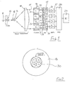
- FIG. 1 there is shown in diagrammatic form the configuration of a polarimeter arranged to operate in accordance with this invention.
- This polarimeter comprises a fibre coupler and GRINROD lens assembly 10, configured to receive an optical fibre 11 and to produce a collimated pencil 12 of light, from the wave issuing from the fibre 11.
- a beam expander comprising a pair of lenses 13 and 14 is mounted on the optical path of the pencil 12, and produces a collimated beam 15 of a diameter many times greater than the diameter of the pencil 12.
- a filter carrier 16 having four Stokes filters F1, F2, F3 and F4 mounted therewithin, is disposed on the optical axis of the beam expander, such that four separate portions of the collimated beam 15 pass through the four filters F1 F2, F3 and F4 respectively.
- Four intensity detectors 17, 18, 19 and 20 are mounted to receive the four filtered beam portions 21, 22, 23 and 24, each intensity detector comprising a lens 25 and a photodetector 26, on to which the respective beam portion is focused by the lens 25.
- the output of each photodetector is supplied to a respective amplifier 27, and the output of all four amplifiers is supplied to an analogue-to-digital converter 28.
- the digitised signal outputs from the converter 28 are fed to a computer, for further processing.
- the filter carrier 16 is of circular overall shape, and has a circular aperture 30 in which are mounted the four filters F1, F2, F3 and F4.
- the four filters comprise Stokes filters (as defined hereinbefore) though filter F1 may in fact simply comprise an open aperture.
- filter F1 comprises a 50% transmission filter, and the other three filters as specified hereinbefore
- the four Stokes parameters S0, S1, S2 and S3 may be derived from the following equations, where I0, I1, I2 and I3 are the detected light intensities of the beam portions, following filtration through the filters F1 to F4:
- S2 2 I2 - 2 I0
- S3 2 I3 - 2 I0
- the fibre carrier and GRINROD lens 10 is supported on a plate 31 carried at one end of a barrel 32 supported in a suitable frame 33.
- the barrel 32 also supports the two lenses 13 and 14 of the beam expander, a carrier 34 for the lens 13 being adjustable to permit the precision focusing adjustment of the expander.
- the filter carrier 16 Also mounted in the frame 33 is the filter carrier 16, and a further carrier 35 for the intensity detectors 17-20.
- the frame 33 supports an end plate 36 on which are provided suitable electrical connectors for wires from the detectors 26.
- An adjustable iris diaphragm 37 is mounted in the frame 33, between the filter carrier 16 and the further carrier 35, to allow uniform attenuation of all four filtered beams. This allows the dynamic range of the polarimeter to be increased, by prevent saturation of the detectors and/or associated amplifiers, should the incoming beam be particularly intense.
- a neutral density filter could be used for this purpose, instead of an adjustable diaphragm.
- the embodiment of polarimeter of this invention is able very rapidly to produce a determination of the state of polarisation of an incoming light wave emanating from an optical fibre.
- the band-width of the apparatus of this invention is in effect limited by the processing speed of the outputs of the four detectors, and thus band-widths of several tens of kHz can be achieved.
Landscapes
- Physics & Mathematics (AREA)
- General Physics & Mathematics (AREA)
- Spectroscopy & Molecular Physics (AREA)
- Investigating, Analyzing Materials By Fluorescence Or Luminescence (AREA)
- Addition Polymer Or Copolymer, Post-Treatments, Or Chemical Modifications (AREA)
- Spectrometry And Color Measurement (AREA)
- Organic Low-Molecular-Weight Compounds And Preparation Thereof (AREA)
- Optical Modulation, Optical Deflection, Nonlinear Optics, Optical Demodulation, Optical Logic Elements (AREA)
Applications Claiming Priority (2)
| Application Number | Priority Date | Filing Date | Title |
|---|---|---|---|
| GB888817382A GB8817382D0 (en) | 1988-07-21 | 1988-07-21 | Optical polarimeter |
| GB8817382 | 1988-07-21 |
Publications (3)
| Publication Number | Publication Date |
|---|---|
| EP0352133A2 true EP0352133A2 (fr) | 1990-01-24 |
| EP0352133A3 EP0352133A3 (fr) | 1991-03-20 |
| EP0352133B1 EP0352133B1 (fr) | 1994-10-26 |
Family
ID=10640866
Family Applications (1)
| Application Number | Title | Priority Date | Filing Date |
|---|---|---|---|
| EP89307447A Expired - Lifetime EP0352133B1 (fr) | 1988-07-21 | 1989-07-21 | Polarimètre optique |
Country Status (6)
| Country | Link |
|---|---|
| US (1) | US5081348A (fr) |
| EP (1) | EP0352133B1 (fr) |
| JP (1) | JPH02196930A (fr) |
| AT (1) | ATE113375T1 (fr) |
| DE (1) | DE68919005D1 (fr) |
| GB (1) | GB8817382D0 (fr) |
Cited By (6)
| Publication number | Priority date | Publication date | Assignee | Title |
|---|---|---|---|---|
| EP0439127A2 (fr) * | 1990-01-22 | 1991-07-31 | Hewlett-Packard Company | Dispositif optique rapide pour la mesure de la polarisation |
| EP0536538A2 (fr) * | 1991-09-06 | 1993-04-14 | Hewlett-Packard Company | Méthode de mesure de la sensibilité de la polarisation des dispositifs optiques |
| EP0654657A2 (fr) * | 1993-11-23 | 1995-05-24 | AT&T Corp. | Système et méthode de mesure de l'atténuation dépendant de la polarisation |
| WO1999008081A1 (fr) * | 1997-08-06 | 1999-02-18 | INSTITUT FüR MIKROTECHNIK MAINZ GMBH | Micropolarimetre |
| EP1705469A1 (fr) * | 2005-03-25 | 2006-09-27 | Raython Company | Polarimètre pour déterminer simultanément les paramètres de Stokes de lumière |
| EP1608153B1 (fr) * | 2004-06-18 | 2008-08-06 | STMicroelectronics Limited | Détecteur d'orientation |
Families Citing this family (25)
| Publication number | Priority date | Publication date | Assignee | Title |
|---|---|---|---|---|
| US5258615A (en) * | 1990-08-03 | 1993-11-02 | Gpt Limited | Optical fiber monitoring by detection of polarization variations |
| US5227623A (en) * | 1992-01-31 | 1993-07-13 | Hewlett-Packard Company | Method and apparatus for measuring polarization mode dispersion in optical devices |
| US5337146A (en) * | 1992-03-30 | 1994-08-09 | University Of New Orleans | Diffraction-grating photopolarimeters and spectrophotopolarimeters |
| JPH0618332A (ja) * | 1992-07-01 | 1994-01-25 | Kokusai Denshin Denwa Co Ltd <Kdd> | ストークス・パラメータ測定方法及び装置 |
| US5805285A (en) * | 1992-09-18 | 1998-09-08 | J.A. Woollam Co. Inc. | Multiple order dispersive optics system and method of use |
| US5666201A (en) * | 1992-09-18 | 1997-09-09 | J.A. Woollam Co. Inc. | Multiple order dispersive optics system and method of use |
| US5416324A (en) * | 1993-06-11 | 1995-05-16 | Chun; Cornell S. L. | Optical imaging device with integrated polarizer |
| US6122404A (en) * | 1998-05-28 | 2000-09-19 | Trw Inc. | Visible stokes polarimetric imager |
| EP1218707A1 (fr) | 1999-07-27 | 2002-07-03 | Colorado School Of Mines | Polarimetres/ ellipsometres spectroscopiques a detection parallele |
| US6490043B1 (en) | 2000-02-14 | 2002-12-03 | Aerodyne Research, Inc. | Polarimetric spectral intensity modulation spectropolarimeter |
| US6836327B1 (en) * | 2001-03-16 | 2004-12-28 | General Photonics Corporation | In-line optical polarimeter based on integration of free-space optical elements |
| WO2002093237A1 (fr) * | 2001-05-15 | 2002-11-21 | Optellios, Inc. | Unite d'analyse de polarisation, procede d'etalonnage et leur optimalisation |
| US20030075676A1 (en) * | 2001-10-24 | 2003-04-24 | Bernard Ruchet | Apparatus for measuring state of polarization of a lightwave |
| US6674532B2 (en) | 2001-11-02 | 2004-01-06 | Vandelden Jay S. | Interferometric polarization interrogating filter assembly and method |
| WO2003087741A1 (fr) * | 2002-04-10 | 2003-10-23 | Terapulse, Inc. | Dispositif de controle du rapport signal-bruit optique presentant une coherence accrue |
| US6744509B2 (en) | 2002-08-20 | 2004-06-01 | Meadowlark Optics, Inc. | Retardance sweep polarimeter and method |
| US6906800B2 (en) * | 2003-03-14 | 2005-06-14 | The United States Of America As Represented By The Secretary Of The Air Force | Polarimeter using quantum well stacks separated by gratings |
| US7800755B1 (en) | 2007-07-02 | 2010-09-21 | The United States Of America As Represented By The Secretary Of The Navy | High-speed polarimeter having a multi-wavelength source |
| US7945130B2 (en) * | 2007-11-15 | 2011-05-17 | General Photonics Corporation | Mode scrambling apparatus for multimode fiber |
| CN102116674B (zh) * | 2010-01-06 | 2012-09-05 | 西安交通大学 | 光偏振态斯托克斯参量的测量方法及系统 |
| US8780433B2 (en) | 2011-09-28 | 2014-07-15 | General Photonics Corporation | Polarization scrambling based on cascaded optical polarization devices having modulated optical retardation |
| US9354118B2 (en) | 2014-02-06 | 2016-05-31 | Film Sense, LLC | Multiple wavelength ellipsometer system and related method |
| JP6065875B2 (ja) * | 2014-06-02 | 2017-01-25 | 横河電機株式会社 | 偏光検査装置 |
| DE102017216358A1 (de) * | 2017-09-14 | 2019-03-14 | Fraunhofer-Gesellschaft zur Förderung der angewandten Forschung e.V. | Vorrichtung und Verfahren zur Bestimmung eines Polarisationszustandes einer elektromagnetischen Welle |
| US10900840B1 (en) * | 2018-10-26 | 2021-01-26 | Arizona Board Of Regents On Behalf Of The University Of Arizona | Snapshot Mueller matrix polarimeter |
Citations (2)
| Publication number | Priority date | Publication date | Assignee | Title |
|---|---|---|---|---|
| FR2570186A1 (fr) * | 1984-09-07 | 1986-03-14 | France Etat | Procede et dispositif de mesure du taux de polarisation |
| WO1986007631A1 (fr) * | 1985-06-21 | 1986-12-31 | Research Corporation | Agencement de photodectecteurs pour mesurer l'etat de polarisation de la lumiere |
Family Cites Families (7)
| Publication number | Priority date | Publication date | Assignee | Title |
|---|---|---|---|---|
| US3556662A (en) * | 1968-05-03 | 1971-01-19 | Us Navy | Device for determining birefringence |
| US4158506A (en) * | 1977-11-15 | 1979-06-19 | The United States Of America As Represented By The Secretary Of The Army | Automatic determination of the polarization state of nanosecond laser pulses |
| US4171916A (en) * | 1977-11-18 | 1979-10-23 | Ishikawajima-Harima Heavy Industries Co., Ltd. | Apparatus and method for measuring the consistency of a pulp suspension |
| DE3004635C2 (de) * | 1980-02-08 | 1982-01-14 | Walter 7500 Karlsruhe Gehmann | Dioptervisier |
| US4698497A (en) * | 1986-05-22 | 1987-10-06 | Westinghouse Electric Corp. | Direct current magneto-optic current transformer |
| US4777358A (en) * | 1987-03-30 | 1988-10-11 | Geo-Centers, Inc. | Optical differential strain gauge |
| US4904085A (en) * | 1988-05-04 | 1990-02-27 | Simmonds Precision Products, Inc. | Polarimetric fiber optic sensor testing apparatus |
-
1988
- 1988-07-21 GB GB888817382A patent/GB8817382D0/en active Pending
-
1989
- 1989-07-21 AT AT89307447T patent/ATE113375T1/de not_active IP Right Cessation
- 1989-07-21 DE DE68919005T patent/DE68919005D1/de not_active Expired - Lifetime
- 1989-07-21 EP EP89307447A patent/EP0352133B1/fr not_active Expired - Lifetime
- 1989-07-21 JP JP1190398A patent/JPH02196930A/ja active Pending
-
1991
- 1991-06-03 US US07/711,504 patent/US5081348A/en not_active Expired - Fee Related
Patent Citations (2)
| Publication number | Priority date | Publication date | Assignee | Title |
|---|---|---|---|---|
| FR2570186A1 (fr) * | 1984-09-07 | 1986-03-14 | France Etat | Procede et dispositif de mesure du taux de polarisation |
| WO1986007631A1 (fr) * | 1985-06-21 | 1986-12-31 | Research Corporation | Agencement de photodectecteurs pour mesurer l'etat de polarisation de la lumiere |
Non-Patent Citations (2)
| Title |
|---|
| APPLIED PHYSICS LETTERS, vol. 35, no. 11, 1st December 1979, pages 840-842, New York, US; R. ULRICH: "Polarization stabilization on single-mode fiber" * |
| OPTIK, vol. 75, no. 1, December 1986, pages 26-36, Stuttgart, DE; S.R. CLOUDE: "Group theory and polarisation algebra" * |
Cited By (12)
| Publication number | Priority date | Publication date | Assignee | Title |
|---|---|---|---|---|
| EP0439127A2 (fr) * | 1990-01-22 | 1991-07-31 | Hewlett-Packard Company | Dispositif optique rapide pour la mesure de la polarisation |
| EP0439127A3 (en) * | 1990-01-22 | 1992-04-29 | Hewlett-Packard Company | Fast optical polarization meter |
| US5298972A (en) * | 1990-01-22 | 1994-03-29 | Hewlett-Packard Company | Method and apparatus for measuring polarization sensitivity of optical devices |
| EP0536538A2 (fr) * | 1991-09-06 | 1993-04-14 | Hewlett-Packard Company | Méthode de mesure de la sensibilité de la polarisation des dispositifs optiques |
| EP0536538A3 (en) * | 1991-09-06 | 1993-12-15 | Hewlett Packard Co | Method and apparatus for measuring polarization sensitivity of optical devices |
| EP0654657A2 (fr) * | 1993-11-23 | 1995-05-24 | AT&T Corp. | Système et méthode de mesure de l'atténuation dépendant de la polarisation |
| EP0654657A3 (fr) * | 1993-11-23 | 1995-11-22 | At & T Corp | Système et méthode de mesure de l'atténuation dépendant de la polarisation. |
| WO1999008081A1 (fr) * | 1997-08-06 | 1999-02-18 | INSTITUT FüR MIKROTECHNIK MAINZ GMBH | Micropolarimetre |
| US6268915B1 (en) | 1997-08-06 | 2001-07-31 | Michael Abraham | Micropolarimeter |
| EP1608153B1 (fr) * | 2004-06-18 | 2008-08-06 | STMicroelectronics Limited | Détecteur d'orientation |
| US7542087B2 (en) | 2004-06-18 | 2009-06-02 | Stmicroelectronics Limited | Orientation sensor and associated methods |
| EP1705469A1 (fr) * | 2005-03-25 | 2006-09-27 | Raython Company | Polarimètre pour déterminer simultanément les paramètres de Stokes de lumière |
Also Published As
| Publication number | Publication date |
|---|---|
| GB8817382D0 (en) | 1988-08-24 |
| US5081348A (en) | 1992-01-14 |
| EP0352133B1 (fr) | 1994-10-26 |
| DE68919005D1 (de) | 1994-12-01 |
| JPH02196930A (ja) | 1990-08-03 |
| ATE113375T1 (de) | 1994-11-15 |
| EP0352133A3 (fr) | 1991-03-20 |
Similar Documents
| Publication | Publication Date | Title |
|---|---|---|
| EP0352133B1 (fr) | Polarimètre optique | |
| US4682024A (en) | Laser radiation warning sensor utilizing polarization | |
| US4655589A (en) | Apparatus for automatic measurement of stress in a transparent body by means of scattered light | |
| ES469049A1 (es) | Polarimetro de fluorescencia para analisis moleculares | |
| CN107941468A (zh) | 一种光纤偏振态的可视化动态检测方法及装置 | |
| JPH0315727A (ja) | 光電測定装置 | |
| US5526109A (en) | Multi-velocity component LDV | |
| EP0024574A1 (fr) | Appareil pour la détermination du profil de l'indice de réfraction de fibres optiques | |
| US3721500A (en) | Instrument for measuring the depolarization of backscattered light | |
| KR100336696B1 (ko) | 편광 분석장치 및 편광 분석방법 | |
| WO1986006845A1 (fr) | Velocimetre de diffraction optique | |
| GB2237950A (en) | Particle size and velocity determination | |
| JPH02311722A (ja) | 光サンプリング波形測定装置 | |
| KR100799445B1 (ko) | 산업용 레이저 속도 측정방법 | |
| JPS59155741A (ja) | 粒子検出装置 | |
| SU822031A1 (ru) | Способ измерени двух компонентСКОРОСТи пОТОКА | |
| SU883875A1 (ru) | Устройство дл дистанционного контрол положени объектов | |
| SU962768A1 (ru) | Устройство дл контрол параметров вибрации | |
| JPS577514A (en) | Optical measuring device | |
| RU2061250C1 (ru) | Акустооптическое устройство для определения частоты радиочастотного сигнала | |
| SU535485A1 (ru) | Устройство дл измерени среднего заутеровского диаметра частиц аэрозол | |
| SU872954A1 (ru) | Устройство дл бесконтактного контрол малых поперечных размеров | |
| Johnson | Multi-velocity component LDV | |
| GB2066458A (en) | Method and Apparatus for Measuring the Optical Retardation of Synthetic Filaments or Film | |
| SU1674095A1 (ru) | Анализатор пространственных спектров |
Legal Events
| Date | Code | Title | Description |
|---|---|---|---|
| PUAI | Public reference made under article 153(3) epc to a published international application that has entered the european phase |
Free format text: ORIGINAL CODE: 0009012 |
|
| AK | Designated contracting states |
Kind code of ref document: A2 Designated state(s): AT BE CH DE ES FR GB GR IT LI LU NL SE |
|
| PUAL | Search report despatched |
Free format text: ORIGINAL CODE: 0009013 |
|
| AK | Designated contracting states |
Kind code of ref document: A3 Designated state(s): AT BE CH DE ES FR GB GR IT LI LU NL SE |
|
| 17P | Request for examination filed |
Effective date: 19910912 |
|
| 17Q | First examination report despatched |
Effective date: 19921012 |
|
| GRAA | (expected) grant |
Free format text: ORIGINAL CODE: 0009210 |
|
| AK | Designated contracting states |
Kind code of ref document: B1 Designated state(s): AT BE CH DE ES FR GB GR IT LI LU NL SE |
|
| PG25 | Lapsed in a contracting state [announced via postgrant information from national office to epo] |
Ref country code: IT Free format text: LAPSE BECAUSE OF FAILURE TO SUBMIT A TRANSLATION OF THE DESCRIPTION OR TO PAY THE FEE WITHIN THE PRE;WARNING: LAPSES OF ITALIAN PATENTS WITH EFFECTIVE DATE BEFORE 2007 MAY HAVE OCCURRED AT ANY TIME BEFORE 2007. THE CORRECT EFFECTIVE DATE MAY BE DIFFERENT FROM THE ONE RECORDED.SCRIBED TIME-LIMIT Effective date: 19941026 Ref country code: NL Effective date: 19941026 Ref country code: FR Effective date: 19941026 Ref country code: CH Effective date: 19941026 Ref country code: ES Free format text: THE PATENT HAS BEEN ANNULLED BY A DECISION OF A NATIONAL AUTHORITY Effective date: 19941026 Ref country code: GR Free format text: LAPSE BECAUSE OF FAILURE TO SUBMIT A TRANSLATION OF THE DESCRIPTION OR TO PAY THE FEE WITHIN THE PRESCRIBED TIME-LIMIT Effective date: 19941026 Ref country code: LI Effective date: 19941026 Ref country code: BE Effective date: 19941026 Ref country code: AT Effective date: 19941026 |
|
| REF | Corresponds to: |
Ref document number: 113375 Country of ref document: AT Date of ref document: 19941115 Kind code of ref document: T |
|
| REF | Corresponds to: |
Ref document number: 68919005 Country of ref document: DE Date of ref document: 19941201 |
|
| PG25 | Lapsed in a contracting state [announced via postgrant information from national office to epo] |
Ref country code: SE Effective date: 19950126 |
|
| PG25 | Lapsed in a contracting state [announced via postgrant information from national office to epo] |
Ref country code: DE Effective date: 19950127 |
|
| REG | Reference to a national code |
Ref country code: CH Ref legal event code: PL |
|
| EN | Fr: translation not filed | ||
| NLV1 | Nl: lapsed or annulled due to failure to fulfill the requirements of art. 29p and 29m of the patents act | ||
| PG25 | Lapsed in a contracting state [announced via postgrant information from national office to epo] |
Ref country code: GB Effective date: 19950721 |
|
| PG25 | Lapsed in a contracting state [announced via postgrant information from national office to epo] |
Ref country code: LU Free format text: LAPSE BECAUSE OF NON-PAYMENT OF DUE FEES Effective date: 19950731 |
|
| PLBE | No opposition filed within time limit |
Free format text: ORIGINAL CODE: 0009261 |
|
| STAA | Information on the status of an ep patent application or granted ep patent |
Free format text: STATUS: NO OPPOSITION FILED WITHIN TIME LIMIT |
|
| 26N | No opposition filed | ||
| GBPC | Gb: european patent ceased through non-payment of renewal fee |
Effective date: 19950721 |