EP0352104A2 - Magneto-optical memory apparatus and optical memory apparatus - Google Patents
Magneto-optical memory apparatus and optical memory apparatus Download PDFInfo
- Publication number
- EP0352104A2 EP0352104A2 EP89307346A EP89307346A EP0352104A2 EP 0352104 A2 EP0352104 A2 EP 0352104A2 EP 89307346 A EP89307346 A EP 89307346A EP 89307346 A EP89307346 A EP 89307346A EP 0352104 A2 EP0352104 A2 EP 0352104A2
- Authority
- EP
- European Patent Office
- Prior art keywords
- optical
- magneto
- reproduction
- recording
- information
- Prior art date
- Legal status (The legal status is an assumption and is not a legal conclusion. Google has not performed a legal analysis and makes no representation as to the accuracy of the status listed.)
- Granted
Links
Images


Classifications
-
- G—PHYSICS
- G11—INFORMATION STORAGE
- G11B—INFORMATION STORAGE BASED ON RELATIVE MOVEMENT BETWEEN RECORD CARRIER AND TRANSDUCER
- G11B7/00—Recording or reproducing by optical means, e.g. recording using a thermal beam of optical radiation by modifying optical properties or the physical structure, reproducing using an optical beam at lower power by sensing optical properties; Record carriers therefor
- G11B7/24—Record carriers characterised by shape, structure or physical properties, or by the selection of the material
- G11B7/2407—Tracks or pits; Shape, structure or physical properties thereof
- G11B7/24085—Pits
-
- G—PHYSICS
- G11—INFORMATION STORAGE
- G11B—INFORMATION STORAGE BASED ON RELATIVE MOVEMENT BETWEEN RECORD CARRIER AND TRANSDUCER
- G11B11/00—Recording on or reproducing from the same record carrier wherein for these two operations the methods are covered by different main groups of groups G11B3/00 - G11B7/00 or by different subgroups of group G11B9/00; Record carriers therefor
- G11B11/10—Recording on or reproducing from the same record carrier wherein for these two operations the methods are covered by different main groups of groups G11B3/00 - G11B7/00 or by different subgroups of group G11B9/00; Record carriers therefor using recording by magnetic means or other means for magnetisation or demagnetisation of a record carrier, e.g. light induced spin magnetisation; Demagnetisation by thermal or stress means in the presence or not of an orienting magnetic field
- G11B11/105—Recording on or reproducing from the same record carrier wherein for these two operations the methods are covered by different main groups of groups G11B3/00 - G11B7/00 or by different subgroups of group G11B9/00; Record carriers therefor using recording by magnetic means or other means for magnetisation or demagnetisation of a record carrier, e.g. light induced spin magnetisation; Demagnetisation by thermal or stress means in the presence or not of an orienting magnetic field using a beam of light or a magnetic field for recording by change of magnetisation and a beam of light for reproducing, i.e. magneto-optical, e.g. light-induced thermomagnetic recording, spin magnetisation recording, Kerr or Faraday effect reproducing
- G11B11/10502—Recording on or reproducing from the same record carrier wherein for these two operations the methods are covered by different main groups of groups G11B3/00 - G11B7/00 or by different subgroups of group G11B9/00; Record carriers therefor using recording by magnetic means or other means for magnetisation or demagnetisation of a record carrier, e.g. light induced spin magnetisation; Demagnetisation by thermal or stress means in the presence or not of an orienting magnetic field using a beam of light or a magnetic field for recording by change of magnetisation and a beam of light for reproducing, i.e. magneto-optical, e.g. light-induced thermomagnetic recording, spin magnetisation recording, Kerr or Faraday effect reproducing characterised by the transducing operation to be executed
- G11B11/10504—Recording
-
- G—PHYSICS
- G11—INFORMATION STORAGE
- G11B—INFORMATION STORAGE BASED ON RELATIVE MOVEMENT BETWEEN RECORD CARRIER AND TRANSDUCER
- G11B11/00—Recording on or reproducing from the same record carrier wherein for these two operations the methods are covered by different main groups of groups G11B3/00 - G11B7/00 or by different subgroups of group G11B9/00; Record carriers therefor
- G11B11/10—Recording on or reproducing from the same record carrier wherein for these two operations the methods are covered by different main groups of groups G11B3/00 - G11B7/00 or by different subgroups of group G11B9/00; Record carriers therefor using recording by magnetic means or other means for magnetisation or demagnetisation of a record carrier, e.g. light induced spin magnetisation; Demagnetisation by thermal or stress means in the presence or not of an orienting magnetic field
- G11B11/105—Recording on or reproducing from the same record carrier wherein for these two operations the methods are covered by different main groups of groups G11B3/00 - G11B7/00 or by different subgroups of group G11B9/00; Record carriers therefor using recording by magnetic means or other means for magnetisation or demagnetisation of a record carrier, e.g. light induced spin magnetisation; Demagnetisation by thermal or stress means in the presence or not of an orienting magnetic field using a beam of light or a magnetic field for recording by change of magnetisation and a beam of light for reproducing, i.e. magneto-optical, e.g. light-induced thermomagnetic recording, spin magnetisation recording, Kerr or Faraday effect reproducing
- G11B11/10502—Recording on or reproducing from the same record carrier wherein for these two operations the methods are covered by different main groups of groups G11B3/00 - G11B7/00 or by different subgroups of group G11B9/00; Record carriers therefor using recording by magnetic means or other means for magnetisation or demagnetisation of a record carrier, e.g. light induced spin magnetisation; Demagnetisation by thermal or stress means in the presence or not of an orienting magnetic field using a beam of light or a magnetic field for recording by change of magnetisation and a beam of light for reproducing, i.e. magneto-optical, e.g. light-induced thermomagnetic recording, spin magnetisation recording, Kerr or Faraday effect reproducing characterised by the transducing operation to be executed
- G11B11/10515—Reproducing
-
- G—PHYSICS
- G11—INFORMATION STORAGE
- G11B—INFORMATION STORAGE BASED ON RELATIVE MOVEMENT BETWEEN RECORD CARRIER AND TRANSDUCER
- G11B11/00—Recording on or reproducing from the same record carrier wherein for these two operations the methods are covered by different main groups of groups G11B3/00 - G11B7/00 or by different subgroups of group G11B9/00; Record carriers therefor
- G11B11/10—Recording on or reproducing from the same record carrier wherein for these two operations the methods are covered by different main groups of groups G11B3/00 - G11B7/00 or by different subgroups of group G11B9/00; Record carriers therefor using recording by magnetic means or other means for magnetisation or demagnetisation of a record carrier, e.g. light induced spin magnetisation; Demagnetisation by thermal or stress means in the presence or not of an orienting magnetic field
- G11B11/105—Recording on or reproducing from the same record carrier wherein for these two operations the methods are covered by different main groups of groups G11B3/00 - G11B7/00 or by different subgroups of group G11B9/00; Record carriers therefor using recording by magnetic means or other means for magnetisation or demagnetisation of a record carrier, e.g. light induced spin magnetisation; Demagnetisation by thermal or stress means in the presence or not of an orienting magnetic field using a beam of light or a magnetic field for recording by change of magnetisation and a beam of light for reproducing, i.e. magneto-optical, e.g. light-induced thermomagnetic recording, spin magnetisation recording, Kerr or Faraday effect reproducing
- G11B11/10502—Recording on or reproducing from the same record carrier wherein for these two operations the methods are covered by different main groups of groups G11B3/00 - G11B7/00 or by different subgroups of group G11B9/00; Record carriers therefor using recording by magnetic means or other means for magnetisation or demagnetisation of a record carrier, e.g. light induced spin magnetisation; Demagnetisation by thermal or stress means in the presence or not of an orienting magnetic field using a beam of light or a magnetic field for recording by change of magnetisation and a beam of light for reproducing, i.e. magneto-optical, e.g. light-induced thermomagnetic recording, spin magnetisation recording, Kerr or Faraday effect reproducing characterised by the transducing operation to be executed
- G11B11/10528—Shaping of magnetic domains, e.g. form, dimensions
-
- G—PHYSICS
- G11—INFORMATION STORAGE
- G11B—INFORMATION STORAGE BASED ON RELATIVE MOVEMENT BETWEEN RECORD CARRIER AND TRANSDUCER
- G11B13/00—Recording simultaneously or selectively by methods covered by different main groups among G11B3/00, G11B5/00, G11B7/00 and G11B9/00; Record carriers therefor not otherwise provided for; Reproducing therefrom not otherwise provided for
- G11B13/04—Recording simultaneously or selectively by methods covered by different main groups among G11B3/00, G11B5/00, G11B7/00 and G11B9/00; Record carriers therefor not otherwise provided for; Reproducing therefrom not otherwise provided for magnetically or by magnetisation and optically or by radiation, for changing or sensing optical properties
-
- G—PHYSICS
- G11—INFORMATION STORAGE
- G11B—INFORMATION STORAGE BASED ON RELATIVE MOVEMENT BETWEEN RECORD CARRIER AND TRANSDUCER
- G11B7/00—Recording or reproducing by optical means, e.g. recording using a thermal beam of optical radiation by modifying optical properties or the physical structure, reproducing using an optical beam at lower power by sensing optical properties; Record carriers therefor
- G11B7/004—Recording, reproducing or erasing methods; Read, write or erase circuits therefor
- G11B7/0045—Recording
-
- G—PHYSICS
- G11—INFORMATION STORAGE
- G11B—INFORMATION STORAGE BASED ON RELATIVE MOVEMENT BETWEEN RECORD CARRIER AND TRANSDUCER
- G11B7/00—Recording or reproducing by optical means, e.g. recording using a thermal beam of optical radiation by modifying optical properties or the physical structure, reproducing using an optical beam at lower power by sensing optical properties; Record carriers therefor
- G11B7/004—Recording, reproducing or erasing methods; Read, write or erase circuits therefor
- G11B7/005—Reproducing
-
- G—PHYSICS
- G11—INFORMATION STORAGE
- G11B—INFORMATION STORAGE BASED ON RELATIVE MOVEMENT BETWEEN RECORD CARRIER AND TRANSDUCER
- G11B7/00—Recording or reproducing by optical means, e.g. recording using a thermal beam of optical radiation by modifying optical properties or the physical structure, reproducing using an optical beam at lower power by sensing optical properties; Record carriers therefor
- G11B7/007—Arrangement of the information on the record carrier, e.g. form of tracks, actual track shape, e.g. wobbled, or cross-section, e.g. v-shaped; Sequential information structures, e.g. sectoring or header formats within a track
- G11B7/013—Arrangement of the information on the record carrier, e.g. form of tracks, actual track shape, e.g. wobbled, or cross-section, e.g. v-shaped; Sequential information structures, e.g. sectoring or header formats within a track for discrete information, i.e. where each information unit is stored in a distinct discrete location, e.g. digital information formats within a data block or sector
Definitions
- the present invention relates to a magneto-optical memory apparatus in which a light beam is projected to a magneto-optical recording medium for recording information therein, erasing and reproducing the information recorded therein.
- the present invention also relates to an optical memory apparatus having an optical information recording medium for recording information, in which a light beam is projected to this optical information recording medium and the information is reproduced by the light reflected therefrom.
- a magneto-optical memory apparatus of the type above-mentioned is arranged such that the optical head projects a laser light condensed to a spot having a diameter of about 1 ⁇ m, to a magneto-optical recording medium capable of recording and erasing information, causing the medium to record information, as well as to read and erase the information recorded therein, and that the signal detector circuit produces a digital reproduction signal based on a reproduction signal supplied from the optical head.
- the signal detector circuit has a peak position detector circuit for detecting the peak positions of information pulses of the reproduction signal, or an amplitude detector circuit for detecting the width and interval of the information pulses. By either one of these circuits, a digital reproduction signal may be obtained from the reproduction signal.
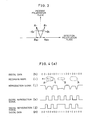
- a conventional magneto-optical memory apparatus includes a magneto-optical disk 101 as the magneto-optical recording medium, and an optical head 102 for recording information in the magneto-optical disk 101, reading and erasing the information recorded therein.
- the optical head 102 includes a semiconductor laser 111, a beam splitter (half-mirror) 112, an objective lens 113, a half-wave plate 116, an analyser 117, a condensing lens 114 and a photo detector 115.
- a light beam emitted from the semiconductor laser 111 passing through the beam splitter (half-mirror) 112 is condensed by the objective lens 113 and projected to the magneto-optical disk 101.
- the reproduction light reflected from the magneto-optical disk 101 passes through the objective lens 113 and is vertically turned, at a portion thereof, by the beam splitter (half-mirror) 112. This light is inclined at a predetermined angle in the polarization direction by the half-wave plate 116.
- the light passes through the analyser 117 and is condensed by the condensing lens 114. Thereafter, the light is incident on the photo detector 115. In the photo detector 115, the reproduction light is converted into an electric signal, which is then sent to a signal detector circuit 23. In the circuit 23, the data are reproduced.
- the magneto-optical disk 101 as the magneto-optical recording medium includes a magnetic thin film having a magnetization facilitating axis in a direction at a right angle to the surface of the thin film. Data may be recorded in the magneto-optical disk 101 as outlined below.
- the optical head 102 projects a laser light to the magnetic thin film of the magneto-optical disk 101
- the portion of the thin film irradiated by the laser light is locally increased in temperature to lower the coercive force thereof.
- the magnetization direction thereof may be inverted in a desired direction. Data are recorded by such inversion of the magnetization direction.
- data reproduction may be carried out as outlined below.
- the polarization plane of the reproduction light which is a reflected light or a transmission light from the magneto-optical recording medium, is rotated by a desired angle according to the magnetization direction of the magneto-optical recording medium.
- the rotation of the polarization plane results from the Faraday effect for the transmission light and from the Kerr effect for the reflected light.
- recording marks (b) are recorded in the magneto-optical disk 101 by inversion of magnetization. It is now supposed that the vectors of the reflected lights from the recording marks are expressed by R-, while the vectors of the reflected lights from other non-marking parts than the recording marks are expressed by R+. Then, a reproduction signal (c) is obtained from the optical head 102 which has received the reflected lights from the magneto-optical disk 101. In the reproduction signal (c), negative-direction pulses are generated by the reflected lights R- from the recording marks, and high-level pulses are generated by the reflected lights R+ from the non-marking parts.
- the signal detector circuit 23 When the signal detector circuit 23 has a peak position detector circuit (not shown), the signal detector circuit 23 to which the reproduction signal (c) above-mentioned has been entered, supplies a digital reproduction signal (d) of which rise portions are identical with the negative-direction peak positions of the reproduction signal (c). On the other hand, when the signal detector circuit 23 includes an amplitude detector circuit (not shown), the signal detector circuit 23 supplies a digital reproduction signal (e) which is in a high level for a predetermined width to the negative-direction peak positions of the reproduction signal (c). Based on the digital reproduction signal (d) or (e), digital data (f) may be obtained as reproduction information.
- a conventional optical memory apparatus comprises: an optical information recording medium in which information is recorded by forming physical concavo-convex portions therein; an optical head for reading the information recorded in the optical information recording medium; and a signal detector circuit for generating a digital reproduction signal from the information read by the optical head.
- the description of the optical head and the signal detector circuit in the optical memory apparatus is here omitted since they have the same functions and the like as those of the optical head and the signal detector circuit in the magneto-optical memory apparatus above-mentioned.
- Fig. 15 (b) recorded in the optical information recording medium are recording marks (b), as recording informaiton, corresponding to the digital data (a).
- recording marks (b) In reading the recording marks by the optical head, the amounts of the reflected lights are increased or decreased by the diffraction thereof due to the concavo-convex portions above-mentioned.
- a reproduction signal (c) is generated.
- the signal detector circuit has a peak position detector circuit
- the signal detector circuit to which the reproduction signal (c) has been entered generates a digital reproduction signal (d) of which rise portions are identical with the negative-direction peak positions of the reproduction signal (c).
- the signal detector circuit when the signal detector circuit includes an amplitude detector circuit, the signal detector circuit supplies a digital reproduction signal (e) which is in a high level for a predetermined width to the negative-direction peak positions of the reproduction signal (c). Based on the digital reproduction signal (d) or (e), digital data (f) may be obtained as reproduction information.
- the magneto-optical memory apparatus mentioned earlier generally employs a magneto-optical recording medium in which formed are (i) physical concavo-convex portions presenting track address information and the like and (ii) recording areas for recording information by inverting the magnetization direction of the magneto-optical recording medium.
- the conventional arrangement above-mentioned presents the problem that it is difficult to enhance the recording density in the magneto-optical recording medium to increase the recording capacity.
- the recording marks need to be further reduced in size.
- the recording marks are reduced in size, it becomes difficult to record such recording marks into the magneto-optical recording medium.
- a laser light is condensed on the magneto-optical recording medium to record the recording marks, it is more difficult to properly form smaller recording marks in view of the degree of diaphragming the laser beam, the characteristics of the magneto-optical recording medium, the ambient temperature and the like. Accordingly, it is difficult to enhance the recording density by forming small-size recording marks.
- the conventional arrangement is not suitable to enhance the recording density.
- each recording mark is shown as an independent mark corresponding to one code.
- the recording density may not be satisfactorily enhanced even in an arrangement in which each recording mark is corresponding to a plurality of codes and the recording mark is made in size identical with other part than the recording mark.
- the present invention provides a magneto-optical memory apparatus comprising: an optical head; a magneto-optical recording medium relatively movable with respect to the optical head, into which recording marks, each having two ends, are recorded as information; the optical head being arranged such that,
- the signal detector circuit may include a peak position detector circuit for detecting the peak positions of information pulses of the reproduction signal and/or an amplitude detector circuit for detecting the width and interval of information pulses having a level not greater than a reference value.
- the magneto-optical memory apparatus may comprise: an optical head; a magneto-optical recording medium relatively movable with respect to the optical head, into which first and second recording marks are recorded as information; the optical head being arranged such that,
- the magneto-optical recording medium may be made of plastic or glass formed in the shape of a disk or a card, and provided with a magnetic thin film having a magnetization facilitating axis in a direction at a right angle to the surface thereof.
- the recording marks as information may be recorded and erased by inversion of the magnetization direction.
- the optical head may include a polarization beam splitter and may be arranged such that the de tection polarization plane is at a right angle to the incident polarization plane.
- the magneto-optical recording medium may be arranged such that each of the first recording marks is made in the form of an ellipse of which length and width are greater than the diameter of the condensing spot of a laser light used at the time of reproduction, and that each of the second recording marks has a length greater than the diameter of the condensing spot.
- the signal detector circuit may include a peak position detector circuit for detecting the peak positions of information pulses of the reproduction signal, and an amplitude detector circuit for detecting the width and interval of information pulses having a level not greater than a reference value.
- the magneto-optical memory apparatus in accordance with the present invention may comprise: an optical head; and a magneto-optical recording medium relatively movable with respect to the optical head, into which recording marks as information are recorded; the optical head having
- the optical system unit may be so arranged as to detect a decrease in amount of received light due to inteference of the reproduction light from a recording mark as irradiated by a light beam with the reproduction light from the non-marking part.
- the optical system unit may include a polarization beam splitter and may be arranged such that the detection polarization plane is at a right angle to the incident polarization plane.
- the optical head may be arranged such that, at the time of reproduction, a condensing spot having a diameter greater than the width of a recording mark of the magneto-optical recording medium, is projected to the magneto-optical recording medium, and the reflected light as a reproduction light is then obtained.
- the magneto-optical memory apparatus in accordance with the present invention may comprise: an optical head; a magneto-optical recording medium relatively movable with respect to the optical head, into which recording marks as information are recorded; the optical head being arranged such that,
- the magneto-optical recording medium may have first and second recording marks, of which ends in the relative moving direction with respect to the optical head, correspond to the second code of digital information composed of two different types of codes, and which are formed in arcuate shapes having different curvatures.
- Each arcuate end of each second recording mark may be longer than that of each first recording mark such that each arcuate end of the second recording mark corresponds to two second codes.
- the magneto-optical recording medium may be arranged such that each recording mark is made in the form of an ellipse of which length and width are greater than the diameter of the condensing spot used at the time of reproduction.
- the optical head may be arranged such that, when a light beam is projected to an end of a recording mark, the detection polarization plane components of the reflected lights from the recording mark and the non-marking part are shifted by 180° in phase.
- the magneto-optical memory apparatus in accordance with the present invention may comprise: an optical head having a two-division photo detector; a magneto-optical recording medium relatively movable with respect to the optical head, into which recording marks as information are recorded, the magneto-optical recording medium being arranged such that
- the magneto-optical recording medium may be arranged such that each of the recording marks is made in the form of an ellipse of which length and width are greater than the diameter of a condensing spot used at the time of reproduction.
- the two-division photo detector may have two divided light receiving portions and the division direction may be identical with the direction of the scanning tracks on the magneto-optical recording medium.
- the signal detector circuit may include a positive direction detector circuit for detecting a positive-direction information pulse in the information pulse of the difference signal supplied from the differential amplifier, a negative direction detector circuit for detecting a negative-direction information pulse, and an OR-gate for calculating a logical sum of these detector circuits.
- the positive direction detector circuit and the negative direction detector circuit may include a peak position detector circuit and/or an amplitude detector circuit.
- the optical head may be arranged such that, when a light beam is projected to an end of a recording mark and the reproduction light is incident on the two-division photo detector, the intensity distributions of such incident light are asymmetric with each other.
- the optical head may be arranged such that, at the time of reproduction, the reproduction lights or reflected lights from a recording mark and a non-marking part are shifted in phase.
- the optical memory apparatus in accordance with the present invention comprises: an optical information recording medium in which recording marks as information are recorded in the form of physical concavo-convex portions, the recording marks being arranged such that the ends thereof in the relative moving direction with respect to an optical head, correspond to a second code sandwiched in between two first codes of digital information composed of two different types of codes; the optical information recording medium being arranged such that when a light beam from the optical head is projected to an end of recording mark, the reflected lights are diffracted due to the concavo-convex portions to decrease the amount of the light incident on the optical head, thereby to generate an information pulse in a reproduction signal supplied from the optical head, the optical head being arranged such that, when the optical head projects a light beam to the optical information recording medium, the reflected light from the optical information recording medium is entered into the optical head to supply a reproduction signal containing an information pulse corresponding to the second code above-ment
- the magneto-optical memory apparatus in accordance with the present invention com strictlyprises: a magneto-optical disk 1 as a magneto-optical recording medium; an optical head 2 for recording information in the magneto-optical disk 1, reading and erasing the information recorded therein; and a signal detector circuit 3 for converting a reproduction signal obtained from the optical head 2 into a digital reproduction signal.
- the magneto-optical disk 1 has a magnetic thin film having a magnetization facilitating axis in a direction at a right angle to the surface of the thin film. By inverting the magnetization direction, first and second recording marks as information may be recorded, erased and so on.
- the magneto-optical disk 1 is movable with respect to the optical head 2.
- a laser light emitted from a semiconductor laser 11 passes through a polarization beam splitter 12 and is condensed by an objective lens 13, as shown in Fig. 2.
- the laser light is then incident on the magneto-optical disk 1.
- the reflected light passes again through the objective lens 13 and is partially dispersed in optical pass by the polarization beam splitter 12.
- the polarization beam splitter 12 is arranged such that the detection polarization plane thereof is at a right angle to the incident polarization plane.
- the polarization beam splitter 12 also serves as an analyser.
- the reflected light is condensed by a condensing lens 14 and converted into an electric signal by a photo detector 15. This signal is then sent to the signal detector circuit 3.
- the optical head 2 is arranged such that, when a laser light as a light beam is projected to the magneto-optical disk 1, recording marks A as first recording marks and recording marks B as second recording marks shown by (i) in Fig. 4 (a) are recorded for digital data (h) in Fig. 4 (a) as digital information.
- each recording mark A each end or edge thereof in the relative moving direction with respect to the optical head 2, corresponds to one "1" sandwiched in between two "0". It is here noted that "0" represents a first code and "1" represents a second code.
- each edge and the intermediate portion between both edges thereof correspond to "1".
- Each recording mark B corresponds, in its entirety, to "1111".
- Each recording mark B has a width narrower than that of each recording mark A.
- Each recording mark A is made in the form of an ellipse of which length and width are greater than the diameter of a condensing spot 4 of a laser light used at the time of reproduction.
- Each recording mark B has a length longer than the diameter of the condensing spot 4. This facilitates the generation of information pulses, to be discussed later.
- the optical head 2 is adapted to supply a reproduction signal when a laser light having the condensing spot 4 having a diameter smaller than the width of each recording mark A and greater than the width of each recording mark B, is projected to the magneto-optical disk 1 and the reflected light is entered into the optical head 2. Only when the optical head 2 receives the reflected light generated at the time an end of a recording mark A or B is irradiated by the laser light, the optical head 2 generates, in the reproduction signal, an information pulse corresponding to "1" as the second code due to interference of the reflected light from the recording mark A or B with the reflected light from the non-marking part.
- the optical head 2 When the laser light is projected to the intermediate portion between both ends of a recording mark B, the optical head 2 is adapted to supply a reproduction signal of which level is lower than a reference value, due to interference of the reflected light from the recording mark B with the reflected light from the non-marking part.
- the optical head 2 includes the polarization beam splitter 12 (serving also as an analyser) in which the incident polarization plane is disposed at a right angle to the detection polarization plane thereof, and the photo detector 15 for converting the output of the polarization beam splitter 12 into an electric signal, as shown in Fig. 3.
- the polarization planes of the reflected lights from the recording mark A or B and the non-marking part are rotated in opposite directions on the laser light incident polarization plane, as shown in Fig. 3.
- the detection polarization plane components of both reflected lights are shifted by 180° in phase. This produces, in a reproduction signal supplied from the photo detector 15, an information pulse or a portion having a level lower than a reference value.
- the signal detector circuit 3 detects, as 1 or the second code, (i) information pulses contained in the reproduction signal supplied from the optical head 2, and (ii) parts between information pulses of which level is not greater than the reference value.
- the signal detector circuit 3 then converts the reproduction signal into the digital reproduction signal. More specifically, the signal detector circuit 3 has a peak position detector circuit (not shown) for detecting the peak positions of information pulses in the reproduction signal, and an amplitude detector circuit (not shown) for detecting the width and interval of information pulses of which level is not greater than the reference value.
- the digital reproduction signal may be obtained from the reproduction signal.
- the optical head 2 projects a light beam to the magneto-optical disk 1, and by inverting the magnetization of the part irradiated by this light beam, the recording marks A, B shown by (i) in Fig. 4 (a) corresponding to the digital data (h) in Fig. 4 (a) are recorded in the magneto-optical disk 1.
- the recording marks A are recorded such that each edge thereof corresponds to "1" sandwiched in between two "0" in the digital data (h).
- Each recording mark B is recorded such that each edge and the part between both edges thereof correspond to "1" and the width thereof is smaller than that of each recording mark A.
- the optical head 2 projects, to the magneto-optical disk 1, a light beam having a light condensing spot with a diameter smaller than the width of each recording mark A and greater than the width of each recording mark B.
- the reflected light thereof is entered to the optical head 2, which produces a reproduction signal (j).
- the Kerr effect causes the polarization plane of the reflected light to be rotated according to the magnetization direction of the non-marking part. It is now supposed that the polarization plane is rotated by + ⁇ K with respect to the incident polarization plane as shown in Fig. 3. Then, the vector of the reflected light is R+.
- the detection polarization plane of the polarization beam splitter 12 is disposed at a right angle to the laser light incident polarization plane, the detection polarization plane component R ⁇ + of the reflected light R+ is obtained by detection at the polarization beam splitter 12, and the reproduction signal (j) obtained from the photo detector 15 is in a high level.
- the polari zation plane of the reflected light is rotated by - ⁇ K and the vector of the reflected light is R-, since the recording mark A is inverted in magnetization with respect to the non-marking part.
- the detection polarization plane component R ⁇ - of the reflected light R- is obtained by detection at the polarization beam splitter 12, and the reproduction signal (j) from the photo detector is in a high level.
- the reproduction signal (j) is slightly low in level. This is because the reflected light from the non-mrking part slightly interferes with the reflected light from the recording mark A.
- Figs. 5 (a) and 6 show an example of the results of calculator simulations of the reproduction signal.
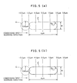
- Fig. 5 (a) shows the relationship between a recording mark C and the light condensing spot 4 in a calculator simulation of reproduction signals in Fig. 6.
- the recording mark C is made in the form of an ellipse having a length of 4 ⁇ m and a width of W, and has at each edge thereof a semi-circular portion having a radius of W/2.
- the light condensing spot 4 is a Gaussian beam of which radius is 0.65 ⁇ m (This is a radius of a circle of which beam intensity is equal to 1/e2).
- the light condensing spot 4 scans in the direction of the line of apsides of the recording mark C.
- the distance in center between the recording mark C and the light condensing spot 4 is shown at the upper portion in Fig. 5 (a).
- the sub strate of the magneto-optical disk 1 having the recording mark C formed thereon, has a refractive index of 1.5.
- the pitch between adjacent tracks in the longitudinal direction on the drawing paper is equal to 1.6 ⁇ m.
- the objective lens has an aperture ratio of 0.55, and the laser light forming the condensing spot 4 has a wavelength of 0.78 ⁇ m.
- Fig. 6 shows the results of a simulation.
- the axis of abscissa represents the scanning direction of the light condensing spot 4 and shows the distance between the center of the recording mark C and the center of the light condensing spot 4.
- the axis of ordinate represents the intensity of a reproduction light incident on the photo detector. This intensity is set to 1.0 when the light condensing spot 4 is located perfectly in other position than the recording mark C, and set to 0.0 when no reproduction light is generated.
- the photo detector 15 generates a reproduction signal corresponding to such a reproduction light.
- the simulations were made under the conditions above-mentioned. It is apparent that the optimum width, depth or height of the recording mark C vary with changes in, for example, the refractive index of a glass substrate, the wavelength ⁇ of the laser light, the aperture ratio of the objective lens and the like.
- the intensity of an externally applied magnetic field is weakened with the diameter of the light condensing spot 4 maintained constant. This enables data to be recorded with the width of the recording mark C reduced. On the contrary, if the externally applied magnetic field is increased, the width of the recording mark C is increased.
- the light intensity of the light condensing spot 4 used at the recording time may vary. That is, as the light intensity is lowered, the width of the recording mark C is reduced, and vice versa.
- the same effect may be achieved by electrically shifting the focus in a focus servo system for condensing the light condensing spot 4 on the magneto-optical disk 1. That is, the addition of offset to the focus enables the light condensing spot 4 to be widened.
- the reproduction signal (j) is entered into the signal detector circuit 3.
- a peak position detector circuit (not shown) in the circuit 3 generates a digital reproduction signal (k) of which rise portions are identical with the negative peaks of the information pulses in the reproduction signal (j).
- the amplitude detector circuit (not shown) of the circuit 3 generates a digital reproduction signal (1) in a high level for a predetermined width, to (a) the negative peak positions and (b) the parts having a level lower than the reference value, of the information pulses in the reproduction signal (j).
- the pulses of these digital reproduction signals (k) and (1) correspond to "1" of the digital data (h).
- digital data (m) as reproduction information may be obtained from both signals (k) and (1).
- the arrangement for obtaining the digital data (m) may be made such that the information pulses generated for the edges of the recording marks A, B are utilized as reproduction clocks and that the reproduction of information is made by detecting the level between edges of a record ing mark B.
- the detection polarization plane of the polarization beam splitter 12 is disposed at a right angle to the laser light incident polarization plane.
- these planes are not necessarily disposed at a right angle to each other, as far as provision is made such that there occurs, at the edges of the recording marks A, B and between the edges of each recording mark B, interference in the reflected lights or transmission lights of the recording marks A, B and the non-marking parts.
- the recording marks above-mentioned are so recorded as to correspond to the second code of the digital information composed of two different types of codes (0, 1). Accordingly, the recording marks may be those as shown in Fig. 8 (b). More specifically, at the time of recording operation of the magneto-optical memory apparatus, a laser light is projected from the semiconductor laser 11 of the optical head 2, and this laser light is converted into a linear polaralization light by the polarization beam splitter 12. The linear polarization light is then incident on the objective lens 13, which condenses the light on the magneto-optical disk 1. The part of the magneto-optical disk 1 irradiated by the laser light is inverted in magnetization and, as shown in Fig. 8, the recording marks (b) are recorded for the digital data (a). Recording is made such that the recording marks corresponds to "1" in the digital data (a).
- a laser light projected from the semiconductor laser 11 is condensed, by the objective lens 13, into the condensing spot 4 having a diameter greater than the width of each recording mark.
- the condensing spot 4 is then projected to the magneto-optical disk 1.
- the reflected light from the magneto-optical disk 1 is incident on the polarization beam splitter 12 through the objective lens 13, and then taken out as a detection polarization plane component corresponding to the magnetization direction of the magneto-optical disk 1.
- the light thus taken out is condensed onto the photo detector 15 by the condensing lens 14 and then converted into an electric signal, which is then generated as a reproduction signal (c).
- the polarization plane of the reflected light is rotated according to the magnetization direction of the non-marking part by the Kerr effect. If the polarization plane is rotated by + ⁇ K as shown in Fig. 3, the vector of the reflected light is R+. Since the detection polarization plane of the polarization beam splitter 12 is disposed at a right angle to the laser light incident polarization plane, a detection polarization plane component R ⁇ + of the reflected light R+ is obtained by detection at the polarization beam splitter 12. The detection polarization plane component R ⁇ + is incident on the photo detector 15. At this time, since no light interference occurrs, a large amount of the light is incident on the photo detector 15. Accordingly, the reproduction signal (c) supplied from the photo detector 15 is in a high level.
- the polarization planes of the reflected lights from the recording mark and the non-marking part are respectively rotated by - ⁇ K and + ⁇ K , since the recording mark is inverted in magnetization with respect to the non-marking part.
- the detection polarization plane components of both reflected lights are shifted by 180° in phase. This causes the reflected lights from the recording mark and the non-marking part to interfere with each other. This reduces the amount of the reflected light incident on the photo detector 15. Accordingly, the reproduction signal (c) supplied from the photo detector 15 is in a low level in a range according to the length of the recording mark.
- the recording marks may be formed as shown by (i) in Fig. 9. More specifically, at the time of recording, the optical head 2 projects a laser light to the magneto-optical disk 1. By inversion in magnetization of the part of the magneto-optical disk 1 irradiated by the laser light, recording marks as shown in Fig. 9 (i) may be recorded in the magneto-optical disk 1 for digital data in Fig. 9 (h). Such recording is made such that each edge of the recording marks corresponds to "1" sandwiched in between two "0" in the digital data (h).
- the optical head 2 projects, to the magneto-optical disk 1, a laser light having the condensing spot 4 of which diameter is smaller than the width of each recording mark.
- the reflected light is entered into the optical head 2, which generates a reproduction signal (j).
- the vector of the reflected light is R+, provided that the polarization plane of the reflected light is rotated by + ⁇ K according to the magnetization direction of the non-marking part by the Kerr effect, as shown in Fig. 3. Since the detection polarization plane of the polarization beam splitter 12 is disposed at a right angle to the laser light incident polarization plane, the detection polarization plane component R ⁇ + of the reflected light R+ is obtained by detection at the polarization beam splitter 12, and a reproduction signal (j) obtained from the photo detector is in a high level.
- the polarization plane of the reflected light is rotated by - ⁇ K and the vector of the reflected light is R-, since the recording mark is inverted in magnetization with respect to the non-marking part.
- the detection polarization plane component R ⁇ - of the reflected light R- is obtained by detection at the polarization beam splitter 12 and the reproduction signal (j) from the photo detector is in a high level.
- the reproduction signal (j) is slightly low in level. This is because the reflected light from the non-mrking part slightly interferes with the reflected light from the recording mark.
- Figs. 11 and 12 With reference to Figs. 11 and 12, the following description will discuss an example using a two-division photo detector, instead of the photo detector 15 in the optical head 2 above-mentioned. It is noted that like parts in Figs. 11 and 12 are designated by like numerals used in the embodiment above-mentioned.
- Fig. 11 shows an example of the magneto-optical memory apparatus using a two-division photo detector as a photo detector.
- a differential amplifier 16 is adapted to supply a difference signal containing an information pulse corresponding to "1" as the second code, based on a difference between output signals from light receiving portions 15′a, 15′b of a two-division photo detector 15′.
- the differential amplifier 16 has a non-inversion input terminal 16a connected to the light receiving portion 15′a of the two division photo detector 15′ in the optical head 2, and an inversion input terminal 16b connected to the light receiving portion 15′b.
- a signal detector circuit 3 includes: a positive-direction signal detector circuit 17 for detecting a positive-direction signal in the difference signal supplied from the differential amplifier 16; a negative-direction signal detector circuit 18 for detecting a negative-direction signal in the difference signal; and an OR-gate 19 for supplying a digital reproduction signal upon reception of the output signals from the positive-direction signal detector circuit 17 and the negative-direction signal detector circuit 18.
- the positive-direction signal detector circuit 17 is adapted to detect, as 1 of digital data, the positive-direction information pulse in the difference signal supplied from the differential amplifier 16, while the negative-direction signal detector circuit 18 is adapted to detect, as 1, the negative-direction information pulse.
- the positive-direction signal detector circuit 17 and the negative-direction signal detector circuit 18 may be formed by, for example, a peak position detector circuit or an amplitude detector circuit. An output from either the positive-direction signal detector circuit 17 or the negative-direction signal detector circuit 18 may be regarded as a digital reproduction signal, from which digital data may be obtained.
- a laser light is projected from a semiconductor laser 11 of an optical head 2 and converted into a linear polarization light by a polarization beam splitter 12.
- the laser light is then incident on an objective lens 13, which condenses the light onto a magneto-optical disk 1.
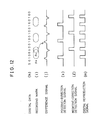
- the part of the magneto-optical disk 1 irradiated by the laser light is inverted in magnetization, and recording marks shown by (i) in Fig. 12 are recorded for digital data shown by (h) in Fig. 12. Recording is made such that each edge of the recording marks corresponds to "1" sandwiched in between two "0" in the digital data (h).
- the laser light projected from the semiconductor laser 11 is condensed, by the objective lens 13, to a condensing spot 4 having a diameter equal to or smaller than the width of each recording mark.
- the light thus condensed is then projected to the magneto-optical disk 1.
- the reflected light from the magneto-optical disk 1 is incident on the polarization beam splitter 12 through the objective lens 13, and taken out as a detection polarization plane component corresponding to the magnetization direction of the magneto-optical disk 1.
- the light thus taken out is condensed onto the light receiving portions 15′a, 15′b of the two-division photo detector 15′ by the condensing lens 14.
- the light thus condensed is converted into an electric signal.
- the outputs from the light receiving portions 15′a, 15′b are entered into the differential amplifier 16.
- the differential amplifier 16 supplies a difference signal (j) as a reproduction signal.
- the polarization plane of the reflected light is rotated according to the magnetization direction of the non-marking part by the Kerr effect.
- the vector of the reflected light is R+. Since the detection polarization plane of the polarization beam splitter 12 is disposed at a right angle to the laser light incident polarization plane, the detection polarization plane component R ⁇ + of the reflected light R+ is obtained by detection at the polarization beam splitter 12.
- the light of the detection polarization plane component R ⁇ + is inci dent on the two-division photo detector 15′.
- the intensity distributions or light recieiving patterns of the light incident on the light receiving portions 15′a and 15′b of the two-division photo detector 15′ are symmetric with each other. Accordingly, the output signals of the light receiving portions 15′a, 15′b are equal to each other, and the difference signal (j) supplied from the differential amplifier 16 is in a reference level.
- the polarization planes of the reflected lights are respectively rotated by - ⁇ K and + ⁇ K , since the recording mark is inverted in magnetization with respect to the non-marking part.
- the detection polarization plane components of both reflected lights are shifted by 180° in phase. This causes the reflected lights from the recording mark and the non-marking part to interfere with each other.
- the light receiving patterns in the light receiving portions 15′a, 15′b are asymmetric with each other.
- the output from the light receiving portion 15′a is greater than the out put of the light receiving portion 15′b, and a positive-direction information pulse is generated in the difference signal (j).
- the polarization plane of the reflected light is rotated by - ⁇ K and the vector of the reflected light is R-.
- the detection polarization plane component R ⁇ - of the reflected light R- is obtained by detection at the polarization beam splitter 12 and is incident on the two-division photo detector 15′.
- the light receiving patterns in the light receiving portions 15′a, 15′b are symmetric with each other and the difference signal (j) is in the reference level, as in the case mentioned earlier. In such a case too, there are instances where the reflected lights from the recording mark and the non-marking part interfere more or less with each other, resulting in a slight variation of the level of the difference signal (j).
- the difference signal (j) is entered into the positive-direction signal detector circuit 17 and negative-direction signal detector circuit 18.
- the positive-direction signal detector circuit 17 supplies a positive-direction detection signal (k) of which rise portions are identical with the positive-direction peak positions of the information pulses of the difference signal (j).
- the negative-direction signal detector circuit 18 supplies a negative-direction detection signal (1) of which rise portions are identical with the negative-direction peak positions of the information pulses of the difference signal (j).
- Both detection signals (k), (1) are entered into an OR-gate 19, which, in turn, generates a digital reproduction signal (m) obtained by logical sum of these detection signals (k), (1).
- Each pulse of the digital reproduction signal (m) corresponds to "1" in the digital data (h). Accordingly, digital data as reproduction information may be obtained from this signal (m).
- the arrangement may be made such that reproduction is made by detecting, for example, the amplitude of each information pulse.
- the polarization beam splitter 12 is arranged such that the detection polarization plane is at a right angle to the laser light incident polarization plane.
- these polarization planes be at a right angle to each other.
- the present invention may not be limited to the arrangement in which the division direction is identical with the scanning track direction.
- the condensing spot 4 has a diameter not greater than each recording mark.
- the diameter of the condensing spot 4 may be greater than each recording mark, as far as the light receiving patterns at the edges are asymmetric.
- the application of the present invention is not limited to the magneto-optical memory apparatus.
- the present invention may also be applied to a photomemory apparatus in which physical concavo-convex recording marks for producing light interference are formed on, for example, a recording medium.
- a 1/4 wave plate may be disposed between the polarization beam splitter 12 and the objective lens 13, thereby to obtain the difference signal (j) in the same manner as above-mentioned. That is, there may be disposed an optical system suitable for the recording medium such that, at the edges of a recording mark, the intensity distributions of the light incident on the two-division photo detector 15′ are asymmetric.
- optical memory apparatus containing, as recording media, recording marks in the form of physical concavo-convex portions adapted to produce an optical interference.
- like parts in the optical memory apparatus are designated by like numerals used in the description of the magneto-optical memory apparatus above-mentioned. The description of such like parts is omitted.
- the optical memory apparatus in accordance with the present invention comprises an optical disk (not shown) as an optical information recording medium, an optical head 2 and a signal detector circuit 3.
- the optical disk has concavo-convex recording marks as shown in Fig. 10 (i).
- Each edge of the recording marks A corresponds to "1" sandwiched in between two "0” and each edge of the recording marks B corresponds to "11" sandwiched in between two “0".
- Each edge of the recording marks A is formed in an arcuate shape of which curvature is different from that of the arcuate shape of each edge of the recording marks B. That is, the arcuate edge of each of the recording marks B is longer than the arcuate edge of each of the recording marks A such that each edge of the recording marks B corresponds to two "1".
- the intermediate part between both edges of each of the recording marks A and B corresponds to "0", and each non-marking part also corresponds to "0".
- the recording marks A and B are arranged such that, when a light beam from the optical head 2 is projected to an edge of the recording marks A and B, the reflected lights are diffracted to reduce the amount of the light incident on the optical head 2, thereby to generate an information pulse in a reproduction signal supplied from the optical head 2.
- each of the recording marks A and B may be in the form of a pit concaved in the light beam incident direction.
- the reflected lights from the recording mark A or B and from the non-marking part are diffracted. This decreases the amount of the light incident on the optical head 2, thereby to generate a negative-direction information pulse in the output from the optical head 2.
- the diameter of the condensing spot 4 of a laser light projected from the optical head 2 may be substantially equal to the width of each of the recording marks A and B, but may be preferably smaller than such width for assuring the generation of such information pulse.
- the reflected light from the recording mark A interferes with the reflected light from the non-marking part, provoking light diffraction. Accordingly, the amount of the reflected light incident on the optical head 2 is reduced, and a negative information pulse is generated in the reproduction signal (j). This is because the diffraction effect at the edge above-mentioned is greater than that at other parts.
- the interference of the reflected lights is small such that the level of the reproduction signal (j) is slightly lowered.
- the reproduction signal (j) is entered into the signal detector circuit 3.
- the signal detector circuit 3 is provided with a peak position detector circuit, there is obtained a digital reproduction signal (k) of which rise portions are identical with the negative peak positions of the information pulses in the reproduction signal (j).
- the signal detector circuit 3 has an amplitude detector circuit, there is obtained a digital reproduction signal (1) which is in a high level for a predetermined width to the negative peak positions of the information pulses.
- the pulses of the digital reproduction signal (k) or (1) correspond to "1" of the digital data (h).
- digital data (m) as reproduction information may be obtained from the signal (k) or (1).
- the width of an information pulse generated in the reproduction signal (j) is increased, since the edge arcuate portion of the recording mark B is longer than the edge arcuate portion of the recording mark A. Accordingly, when the reproduction signal (j) is entered into the signal detector circuit 3 having the amplitude detector circuit, the digital reproduction signal (1) obtained from the signal detector circuit 3 is in a high level to the negative peak positions of the information pulses of the reproduction signal (j), and has pulses of which widths are corresponding to the widths of the information pulses of the reproduction signal (j). More specifically, each pulse of the digital reproduction signal (1) has a width corresponding to "11" of the digital data (h). Accordingly, there are obtained digital data (m), as reproduction information, from the digital reproduction signal (1).
- the recording marks at the outer periphery are read as having a smaller curvature, since the running speed of the disk is higher at the outer periphery thereof. Accordingly, the width of the reproduction signal detected at the edge is greater for the inner part. If such width is regarded as one information, such information may be recognized as a track position information (ID information). That is, in the method above-mentioned, the curvature of the edge of a recording mark is understood in an analogue manner.
- Figs. 5 (b) and 7 show the results of calculator simulations of the reproduction signal.
- Fig. 5 (b) shows the relationship between a recording mark C and the light condensing spot 4 in a calculator simulation of reproduction signals in Fig. 6 and 7.
- the recording mark C is made in the form of an ellipse having a length of 4 ⁇ m and a width of W, and has at each edge thereof a semi-circular portion having a radius of W/2.
- the light condensing spot 4 is a Gaussian beam of which radius is 0.65 ⁇ m (This is a radius of a circle of which beam intensity is equal to 1/e2).
- the light condensing spot 4 scans in the direction of the line of apsides of the recording mark C.
- the distance in center between the recording mark C and the light condensing spot 4 is shown at the upper portion in Fig. 5 (b).
- the substrate of the optical disk (not shown) having the recording mark C formed thereon, has a refractive index of 1.5.
- the pitch between adjacent tracks in the longitudinal direction on the drawing paper is equal to 1.6 ⁇ m.
- the objective lens has an aperture ratio of 0.55, and the laser light forming the condensing spot 4 has a wavelength of 0.78 ⁇ m.
- Fig. 6 shows the results of a simulation in which the recording mark C has a depth or height D of 0.13 ⁇ m.
- the axis of abscissa represents the scanning direction of the light condensing spot 4 and shows the distance between the center of the recording mark C and the center of the light condensing spot 4.
- the axis of ordinate represents the intensity of a reproduction light incident on the photo detector. This intensity is set to 1.0 when the light condensing spot 4 is located perfectly in other position than the recording mark C, and set to 0.0 when no reproduction light is generated.
- the photo detector 15 generates a reproduction signal corresponding to such a reproduction light.
- Fig. 7 shows the results of a simulation in which the recording mark C has a depth or height D of 0.065 ⁇ m.
- Fig. 7 shows signals of which widths are generally smaller than those shown in Fig. 6, but generally presents a trend similar to that in Fig. 6.
- the information pulse may be increased for the recording mark C having a depth or height D of about 0.13 ⁇ m.
- the simulations were made under the conditions above-mentioned. It is apparent that the optimum width, depth or height of the recording mark C vary with changes in, for. example, the refractive index of a glass substrate, the wavelength ⁇ of the laser light, the aperture ratio of the objective lens and the like.
- the intensity of an externally applied magnetic field is weakened with the diameter of the light condensing spot 4 maintained constant. This enables data to be recorded with the width of the recording mark C reduced. On the contrary, if the externally applied magnetic field is increased, the width of the recording mark C is increased.
- the light intensity of the light condensing spot 4 used at the recording time may vary. That is, as the light intensity is lowered, the width of the recording mark C is reduced, and vice versa.
- the same effect may be achieved by electrically shifting the focus in a focus servo system for condensing the light condensing spot 4 on the optical disk . That is, the addition of offset to the focus enables the light condensing spot 4 to be widened.
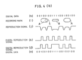
- FIG. 4 (b) Another example of the concavo-convex recording marks are shown in Fig. 4 (b).
- the recording marks in Fig. 4 (b) are arranged such that, only when a laser light as a light beam from the optical head 2 is projected to a recording mark edge, the reflected lights are diffracted to decrease the amount of the light incident on the optical head, thereby to generate an information pulse in a reproduction signal supplied from the optical head 2.
- a reproduction signal (j) supplied from the optical head 2 is in a high level as shown in Fig. 4 (b).
- the laser light from the optical head 2 is projected to an edge of a recording mark A, the reflected lights from the recording mark A and the non-marking part interfere with each other, provoking light diffraction.
- This decreases the amount of the light incident on the optical head 2 to generate a negative-direction information pulse in the reproduction signal (j). This is because the diffraction efficiency at the edge above-mentioned is greater than that at other parts.
- the laser light is projected to the intermediate part of both edges of a recording mark A, the reflected lights are hardly diffracted so that the reproduction signal (j) is in a high level.
- the descriptions have been respectively made of the magneto-optical memory apparatus and the optical memory apparatus. It is however noted that the present invention may also be applied to a magneto-optical memory apparatus in which the magneto-optical recording medium previously contains physical concavo-convex portions presenting the track address information.
- the magneto-optical memory apparatus in accordance with the present invention com prises: an optical head; a magneto-optical recording medium relatively movable with respect to the optical head, into which recording marks, each having two ends, are recorded as information; the optical head being arranged such that,
- each recording mark may contain a number of information to enhance the recording density in the magneto-optical recording medium, enabling to increase the recording capacity thereof.
- the recording density is not enhanced by merely making the recording marks in a compact design. Accordingly, the recording marks may be readily made in a large size and in a suitable shape.
- the number of component elements of the optical system may be reduced. This simplifies the optical system in arrangement.
- the signal detector circuit may include a peak position detector circuit for detecting the peak positions of information pulses of the reproduction signal and/or an amplitude detector circuit for detecting the width and interval of information pulses of which level is not greater than a reference value.
- the magneto-optical memory apparatus may comprise: an optical head; a magneto-optical recording medium relatively movable with respect to the optical head, into which first and second recording marks are recorded as information; the optical head being arranged such that,
- the magneto-optical recording medium may be made of plastic or glass and formed in the shape of a disk or a card, and provided with a magnetic thin film having a magnetization facilitating axis in a direction at a right angle to the surface thereof.
- the recording marks as information may be recorded and erased by inversion of the magnetization direction.
- the optical head may include a polarization beam splitter and may be arranged such that the de tection polarization plane is at a right angle to the incident polarization plane.
- the magneto-optical recording medium may be arranged such that each of the first recording marks is made in the form of an ellipse of which length and width are greater than the diameter of the condensing spot of a laser light used at the time of reproduction, and each of the second recording marks has a length greater than the diameter of the condensing spot.
- the signal detector circuit may include a peak position detector circuit for detecting the peak positions of information pulses of the reproduction signal and an amplitude detector circuit for detecting the width and interval of information pulses having a level not greater than a reference value.
- the magneto-optical memory apparatus in accordance with the present invention may comprise: an optical head; and a magneto-optical recording medium relatively movable with respect to the optical head, into which recording marks as information are recorded; the optical head having
- the optical system may be so arranged as to detect a decrease in amount of received light due to inteference of the reproduction light from a recording mark as irradiated by a light beam, with the reproduction light from the non-marking part.
- the optical system may include a polarization beam splitter and may be arranged such that the detection polarization plane is at a right angle to the incident polarization plane.
- the optical head may be arranged such that, at the time of reproduction, a condensing spot having a diameter greater than the width of a recording mark of the magneto-optical recording medium, is projected to the magneto-optical recording medium, and the reflected light as a reproduction light is obtained.
- the magneto-optical memory apparatus in accordance with the present invention may comprise: an optical head; a magneto-optical recording medium relatively movable with respect to the optical head, into which recording marks as information are recorded; the optical head being arranged such that,
- the magneto-optical recording medium may have first and second recording marks, of which ends in the relative moving direction with respect to the optical head, correspond to the second code of digital information composed of two different types of codes, and which are formed in arcuate shapes having different curvatures.
- Each arcuate end of a second recording mark may be longer than that of a first recording mark such that each arcuate end of the second recording mark corresponds to two second codes.
- the magneto-optical recording medium may be arranged such that each recording mark is made in the form of an ellipse of which length and width are greater than the diameter of the condensing spot used at the time of reproduction.
- the optical head may be arranged such that, when a light beam is projected to an end of a recording mark, the detection polarization plane components of the reflected lights from the recording mark and the non-marking part are shifted by 180° in phase.
- the magneto-optical memory apparatus in accordance with the present invention may comprise: an optical head having a two-division photo detector; a magneto-optical recording medium relatively movable with respect to the optical head, into which recording marks as information are recorded, the magneto-optical recording medium being arranged such that
- the magneto-optical recording medium may be arranged such that each of the recording marks is made in the form of an ellipse of which length and width are greater than the diameter of a condensing spot used at the time of reproduction.
- the two-division photo detector may have two divided light receiving portions such that the division direction is identical with the direction of the scanning tracks on the magneto-optical recording medium.
- the signal detector circuit may include a positive direction detector circuit for detecting a positive-direction information pulse in the information pulse of the difference signal supplied from the differential amplifier, a negative-direction detector circuit for detecting a negative-direction information pulse, and an OR-gate for calculating a logical sum of these detector circuits.
- the positive direction detector circuit and the negative direction detector circuit may include a peak position detector circuit and/or an amplitude detector circuit.
- the optical head may be arranged such that, when a light beam is projected to an end of a recording mark and the reproduction light is incident on the two-division photo detector, the intensity distributions of such incident light are asymmetric with each other.
- the optical head may be arranged such that, at the time of reproduction, the reproduction lights or reflected lights from a recording mark and a non-marking part are shifted in phase.
- the optical memory apparatus in accordance with the present invention is characterized in that: the recording marks as information are recorded, in the form of physical concavo-convex portions, in the optical information recording medium; the recording marks are arranged such that the ends thereof in the relative moving direction with respect to the optical head, correspond to a second code sandwiched in between two first codes of digital information composed of two different types of codes; and when a light beam from the optical head is projected to an end of a recording mark, the reflected lights are diffracted due to the concavo-convex portions to decrease the amount of the light incident on the optical head, thereby to generate an information pulse in a reproduction signal supplied from the optical head.
- first and second recording marks as information are recorded, in the form of physical concavo-convex portions, in an optical information recording medium; the ends of the first and second recording marks in the relative moving direction with respect to an optical head, correspond to a second code of digital information composed of two different types of first and second codes; only when a light beam projected from the optical head is projected to an end of the recording marks, the reflected lights are diffracted due to the concavo-convex portions to decrease the amount of the light incident on the optical head, thereby to generate an information pulse in a reproduction signal supplied from the optical head; the intermediate part of both ends of each of the second recording marks corresponds to the second code above-mentioned; and each of the second recording marks has a width smaller than that of each of the first recording marks such that, when the light beam from the optical head is projected to the intermediate part of a second recording mark, the reflected lights are diffracted due to the concavo-convex portions to
- each recording mark contains a number of information to enhance the recording density in the optical information recording medium, thereby to increase the recording capacity.
- the recording density is not enhanced by merely making the recording marks in a compact design. Accordingly, the recording marks may be made in a large size and in a suitable shape. This facilitates the transfer of the recording marks made by plastic forming or the like.
Abstract
an optical head;
a magneto-optical recording medium relatively movable with respect to the optical head, into which recording marks, each having two ends, are recorded as information;
the optical head being arranged such that,
- (i) at the time of recording into the magneto-optical recording medium, the recording marks are recorded such that the ends of each recording mark correspond to a second code of digital information composed of two different types of codes,
- (ii) at the time of reproduction, a light beam having a condensing spot is projected to the magneto-optical recording medium and, when a reproduction light containing reproduction information is entered to the optical head from the magneto-optical recording medium, a reproduction signal is supplied, and
- (iii) when the light beam is projected to a recording mark, an information pulse corresponding to the second code is generated in the reproduction signal, only when the reproduction light from the recording mark interferes with the reproduction light from the non-marking part; and
Description
- The present invention relates to a magneto-optical memory apparatus in which a light beam is projected to a magneto-optical recording medium for recording information therein, erasing and reproducing the information recorded therein. The present invention also relates to an optical memory apparatus having an optical information recording medium for recording information, in which a light beam is projected to this optical information recording medium and the information is reproduced by the light reflected therefrom.
-
- A magneto-optical memory apparatus of the type above-mentioned is arranged such that the optical head projects a laser light condensed to a spot having a diameter of about 1 µm, to a magneto-optical recording medium capable of recording and erasing information, causing the medium to record information, as well as to read and erase the information recorded therein, and that the signal detector circuit produces a digital reproduction signal based on a reproduction signal supplied from the optical head. The signal detector circuit has a peak position detector circuit for detecting the peak positions of information pulses of the reproduction signal, or an amplitude detector circuit for detecting the width and interval of the information pulses. By either one of these circuits, a digital reproduction signal may be obtained from the reproduction signal.
- As shown in Fig. 13, a conventional magneto-optical memory apparatus includes a magneto-
optical disk 101 as the magneto-optical recording medium, and anoptical head 102 for recording information in the magneto-optical disk 101, reading and erasing the information recorded therein. - The
optical head 102 includes asemiconductor laser 111, a beam splitter (half-mirror) 112, anobjective lens 113, a half-wave plate 116, ananalyser 117, acondensing lens 114 and aphoto detector 115. A light beam emitted from thesemiconductor laser 111 passing through the beam splitter (half-mirror) 112 is condensed by theobjective lens 113 and projected to the magneto-optical disk 101. The reproduction light reflected from the magneto-optical disk 101 passes through theobjective lens 113 and is vertically turned, at a portion thereof, by the beam splitter (half-mirror) 112. This light is inclined at a predetermined angle in the polarization direction by the half-wave plate 116. Then, the light passes through theanalyser 117 and is condensed by thecondensing lens 114. Thereafter, the light is incident on thephoto detector 115. In thephoto detector 115, the reproduction light is converted into an electric signal, which is then sent to asignal detector circuit 23. In thecircuit 23, the data are reproduced. - The magneto-
optical disk 101 as the magneto-optical recording medium, includes a magnetic thin film having a magnetization facilitating axis in a direction at a right angle to the surface of the thin film. Data may be recorded in the magneto-optical disk 101 as outlined below. - When the
optical head 102 projects a laser light to the magnetic thin film of the magneto-optical disk 101, the portion of the thin film irradiated by the laser light, is locally increased in temperature to lower the coercive force thereof. When a magnetic field is external ly applied to this portion, the magnetization direction thereof may be inverted in a desired direction. Data are recorded by such inversion of the magnetization direction. - On the other hand, data reproduction may be carried out as outlined below.
- When a laser light of linear polarization weaker than that used at the time of recording, is projected to the magneto-optical recording medium, the polarization plane of the reproduction light which is a reflected light or a transmission light from the magneto-optical recording medium, is rotated by a desired angle according to the magnetization direction of the magneto-optical recording medium. The rotation of the polarization plane results from the Faraday effect for the transmission light and from the Kerr effect for the reflected light. For example, it is now supposed that the vector of the reflected light in a magnetization direction of the magneto-optical recording medium is expressed by R+, while the vector of the reflected light in the inverted magnetization direction with respect to the first-mentioned magnetization direction is expressed by R-. In this case, the rotation angles of the polarization planes corresponding to these reflected lights R+ and R- with respect to the incident polarization plane, are respectively expressed by +ϑK and -8K, as shown in Fig. 14. Provision is made such that the re production signal as an electric signal is obtained by detecting the detection polarization plane components Rα+ and Rα- of the reflected lights R+ and R- on the detection polarization plane set at 45° with respect to the incident polarization plane. At this time, Rα- and Rα+ are in low and high levels of a binary code, respectively.
- The following description will discuss in more detail the operation of the magneto-optical memory apparatus having the principle above-mentioned, with reference to Fig. 15 (a).
- Corresponding to digital data (a) shown in Fig. 15 (a), recording marks (b) are recorded in the magneto-
optical disk 101 by inversion of magnetization. It is now supposed that the vectors of the reflected lights from the recording marks are expressed by R-, while the vectors of the reflected lights from other non-marking parts than the recording marks are expressed by R+. Then, a reproduction signal (c) is obtained from theoptical head 102 which has received the reflected lights from the magneto-optical disk 101. In the reproduction signal (c), negative-direction pulses are generated by the reflected lights R- from the recording marks, and high-level pulses are generated by the reflected lights R+ from the non-marking parts. - When the
signal detector circuit 23 has a peak position detector circuit (not shown), thesignal detector circuit 23 to which the reproduction signal (c) above-mentioned has been entered, supplies a digital reproduction signal (d) of which rise portions are identical with the negative-direction peak positions of the reproduction signal (c). On the other hand, when thesignal detector circuit 23 includes an amplitude detector circuit (not shown), thesignal detector circuit 23 supplies a digital reproduction signal (e) which is in a high level for a predetermined width to the negative-direction peak positions of the reproduction signal (c). Based on the digital reproduction signal (d) or (e), digital data (f) may be obtained as reproduction information. - A conventional optical memory apparatus comprises: an optical information recording medium in which information is recorded by forming physical concavo-convex portions therein; an optical head for reading the information recorded in the optical information recording medium; and a signal detector circuit for generating a digital reproduction signal from the information read by the optical head. The description of the optical head and the signal detector circuit in the optical memory apparatus is here omitted since they have the same functions and the like as those of the optical head and the signal detector circuit in the magneto-optical memory apparatus above-mentioned.
- The following description will discuss the operation of the optical memory apparatus with reference to Fig. 15 (b).
- As shown in Fig. 15 (b), recorded in the optical information recording medium are recording marks (b), as recording informaiton, corresponding to the digital data (a). In reading the recording marks by the optical head, the amounts of the reflected lights are increased or decreased by the diffraction thereof due to the concavo-convex portions above-mentioned. Thus, a reproduction signal (c) is generated. When the signal detector circuit has a peak position detector circuit, the signal detector circuit to which the reproduction signal (c) has been entered, generates a digital reproduction signal (d) of which rise portions are identical with the negative-direction peak positions of the reproduction signal (c). On the other hand, when the signal detector circuit includes an amplitude detector circuit, the signal detector circuit supplies a digital reproduction signal (e) which is in a high level for a predetermined width to the negative-direction peak positions of the reproduction signal (c). Based on the digital reproduction signal (d) or (e), digital data (f) may be obtained as reproduction information.
- The magneto-optical memory apparatus mentioned earlier generally employs a magneto-optical recording medium in which formed are (i) physical concavo-convex portions presenting track address information and the like and (ii) recording areas for recording information by inverting the magnetization direction of the magneto-optical recording medium.
- The conventional arrangement above-mentioned presents the problem that it is difficult to enhance the recording density in the magneto-optical recording medium to increase the recording capacity.
- More specifically, to enhance the recording density of the magneto-optical recording medium in the arrangement above-mentioned, the recording marks need to be further reduced in size. However, as the recording marks are reduced in size, it becomes difficult to record such recording marks into the magneto-optical recording medium. For example, when a laser light is condensed on the magneto-optical recording medium to record the recording marks, it is more difficult to properly form smaller recording marks in view of the degree of diaphragming the laser beam, the characteristics of the magneto-optical recording medium, the ambient temperature and the like. Accordingly, it is difficult to enhance the recording density by forming small-size recording marks. Thus, the conventional arrangement is not suitable to enhance the recording density.
- For convenience' sake, each recording mark is shown as an independent mark corresponding to one code. However, the recording density may not be satisfactorily enhanced even in an arrangement in which each recording mark is corresponding to a plurality of codes and the recording mark is made in size identical with other part than the recording mark.
- It is an object of the present invention to provide a magneto-optical memory apparatus or an optical memory apparatus in which each recording mark contains a number of information to enhance the recording density in the magneto-optical recording medium or the optical information recording medium, enabling to increase the recording capacity.
- It is another object of the present invention to provide a magneto-optical memory apparatus in which the recording marks are made in a large size to facilitate the formation of the recording marks.
- It is a further object of the present invention to provide a magneto-optical memory apparatus in which the number of component elements of the optical system is reduced to simplify the optical system in arrangement.
- It is still another object of the present invention to provide an optical memory apparatus in which the re cording marks are made in a large size to facilitate the formation of the recording marks, enabling to facilitate the transfer of the recording marks made by plastic forming or the like.
- It is a still further object of the present invention to provide a magneto-optical memory apparatus having a magneto-optical recording medium which previously contains physical concavo-convex portions presenting track address information and the like, recording marks being formed in a large size in the magneto-optical recording medium to facilitate the formation of the recording marks.
- To achieve the objects above-mentioned, the present invention provides a magneto-optical memory apparatus comprising:
an optical head;
a magneto-optical recording medium relatively movable with respect to the optical head, into which recording marks, each having two ends, are recorded as information;
the optical head being arranged such that, - (i) at the time of recording into the magneto-optical recording medium, the recording marks are recorded such that the ends of each recording mark correspond to a second code of digital information composed of two different types of codes,
- (ii) at the time of reproduction, a light beam having a condensing spot is projected to the magneto-optical recording medium and a reproduction signal is supplied when a reproduction light containing reproduction information is entered into the optical head from the magneto-optical recording medium, and
- (iii) when the light beam is projected to a recording mark, an information pulse corresponding to the second code is generated in the reproduction signal, only when there occurs an interference of reproduction lights from the recording mark and the non-marking part; and
- The signal detector circuit may include a peak position detector circuit for detecting the peak positions of information pulses of the reproduction signal and/or an amplitude detector circuit for detecting the width and interval of information pulses having a level not greater than a reference value.
- The magneto-optical memory apparatus according to the present invention may comprise:
an optical head;
a magneto-optical recording medium relatively movable with respect to the optical head, into which first and second recording marks are recorded as information;
the optical head being arranged such that, - (i) at the time of recording to the magneto-optical recording medium, the first and second recording marks are recorded such that the ends thereof in the relative moving direction with respect to the optical head, correspond to a second code of digital information composed of two different types of codes,
- (ii) each of the second recording marks is recorded in a width smaller than that of each of the first recording marks such that the part between both ends of each second recording mark corresponds to the second code above-mentioned,
- (iii) at the time of reproduction, a light beam having a condensing spot having a diameter smaller than the width of each first recording mark and greater than the width of each second recording mark, is projected to the magneto-optical recording medium,
- (iv) upon reception of a reproduction light containing reproduction information from the magneto-optical recording medium, a reproduction signal is supplied, and only at the time of reception of the reproduction light generated by irradiation of a light beam to an end of a first or second recording mark, an information pulse corresponding to the second code above-mentioned is generated in the reproduction signal, due to interference of the reproduction light from the first or second recording mark with the reproduction light from the non-marking part, and
- (v) when the light beam is projected to the part between both ends of a second recording mark, there is supplied a reproduction signal having a level lower than a reference value due to interference of the reproduction light from the second recording mark with the reproduction light from the non-marking part; and
- The magneto-optical recording medium may be made of plastic or glass formed in the shape of a disk or a card, and provided with a magnetic thin film having a magnetization facilitating axis in a direction at a right angle to the surface thereof. The recording marks as information may be recorded and erased by inversion of the magnetization direction.
- To reduce the number of component elements in the optical system, the optical head may include a polarization beam splitter and may be arranged such that the de tection polarization plane is at a right angle to the incident polarization plane.
- To facilitate the generation of the information pulses, the magneto-optical recording medium may be arranged such that each of the first recording marks is made in the form of an ellipse of which length and width are greater than the diameter of the condensing spot of a laser light used at the time of reproduction, and that each of the second recording marks has a length greater than the diameter of the condensing spot.
- The signal detector circuit may include a peak position detector circuit for detecting the peak positions of information pulses of the reproduction signal, and an amplitude detector circuit for detecting the width and interval of information pulses having a level not greater than a reference value.
- The magneto-optical memory apparatus in accordance with the present invention may comprise:
an optical head; and
a magneto-optical recording medium relatively movable with respect to the optical head, into which recording marks as information are recorded;
the optical head having - (i) an optical system unit for supplying interference lights, in opposite phases, respectively obtained from a reproduction light from a recording mark as irradiated by a light beam and a reproduction light from the non-marking part, and
- (ii) a photo detector for converting the incident lights into electric signals each having a level corresponding to the amount of the incident light;
- (i) at the time of recording into the magneto-optical recording medium, there are recorded recording marks corresponding to a second code of digital information composed of two different types of codes,
- (ii) at the time of reproduction, a light beam having a condensing spot having a diameter greater than the width of each recording mark, is projected to the magneto-optical recording medium, from which supplied are reproduction lights containing reproduction information, and
- (iii) the inteference lights obtained from these reproduction lights are supplied to the photo detector, from which a reproduction signal is supplied.
- The optical system unit may be so arranged as to detect a decrease in amount of received light due to inteference of the reproduction light from a recording mark as irradiated by a light beam with the reproduction light from the non-marking part.
- To reduce the number of component elements of the optical system, the optical system unit may include a polarization beam splitter and may be arranged such that the detection polarization plane is at a right angle to the incident polarization plane.
- The optical head may be arranged such that, at the time of reproduction, a condensing spot having a diameter greater than the width of a recording mark of the magneto-optical recording medium, is projected to the magneto-optical recording medium, and the reflected light as a reproduction light is then obtained.
- The magneto-optical memory apparatus in accordance with the present invention may comprise:
an optical head;
a magneto-optical recording medium relatively movable with respect to the optical head, into which recording marks as information are recorded;
the optical head being arranged such that, - (i) at the time of recording into the magneto-optical recording medium, recording marks are recorded such that the ends thereof in the relative moving direction with respect to the optical head, correspond to a second code sandwiched in between two first codes of digital information composed of two different types of codes, and
- (ii) at the time of reproduction, a light beam having a condensing spot having a diameter not greater than the width of each recording mark, is projected to the magneto-optical recording medium, and a reproduction signal is supplied upon reception of a reproduction light containing reproduction information from the magneto-optical recording medium, and an information pulse corresponding to the second code is generated in the reproduction signal due to interference of the reproduction light from a recording mark with the reproduction light from the non-marking part upon reception of the reproduction light generated when an end of a recording mark is irradiated by the light beam; and
- The magneto-optical recording medium may have first and second recording marks, of which ends in the relative moving direction with respect to the optical head, correspond to the second code of digital information composed of two different types of codes, and which are formed in arcuate shapes having different curvatures. Each arcuate end of each second recording mark may be longer than that of each first recording mark such that each arcuate end of the second recording mark corresponds to two second codes.
- To facilitate the generation of information pulses, the magneto-optical recording medium may be arranged such that each recording mark is made in the form of an ellipse of which length and width are greater than the diameter of the condensing spot used at the time of reproduction.
- The optical head may be arranged such that, when a light beam is projected to an end of a recording mark, the detection polarization plane components of the reflected lights from the recording mark and the non-marking part are shifted by 180° in phase.
- The magneto-optical memory apparatus in accordance with the present invention may comprise:
an optical head having a two-division photo detector;
a magneto-optical recording medium relatively movable with respect to the optical head, into which recording marks as information are recorded,
the magneto-optical recording medium being arranged such that - (i) each end of the recording marks in the relative moving direction with respectot the optical head, corresponds to a second code sandwiched in between two first codes of digital information composed of two different types of codes, and
- (ii) when a light beam from the optical head is projected to an end of a recording mark, the intensity distributions of the reproduction light in the two-division photo detector of the optical head are asymmetric with each other due to light interference;
- To facilitate the generation of the information pulse, the magneto-optical recording medium may be arranged such that each of the recording marks is made in the form of an ellipse of which length and width are greater than the diameter of a condensing spot used at the time of reproduction.
- The two-division photo detector may have two divided light receiving portions and the division direction may be identical with the direction of the scanning tracks on the magneto-optical recording medium.
- The signal detector circuit may include a positive direction detector circuit for detecting a positive-direction information pulse in the information pulse of the difference signal supplied from the differential amplifier, a negative direction detector circuit for detecting a negative-direction information pulse, and an OR-gate for calculating a logical sum of these detector circuits.
- The positive direction detector circuit and the negative direction detector circuit may include a peak position detector circuit and/or an amplitude detector circuit.
- The optical head may be arranged such that, when a light beam is projected to an end of a recording mark and the reproduction light is incident on the two-division photo detector, the intensity distributions of such incident light are asymmetric with each other.
- The optical head may be arranged such that, at the time of reproduction, the reproduction lights or reflected lights from a recording mark and a non-marking part are shifted in phase.
- To achieve the objects above-mentioned, the optical memory apparatus in accordance with the present invention comprises:
an optical information recording medium in which recording marks as information are recorded in the form of physical concavo-convex portions, the recording marks being arranged such that the ends thereof in the relative moving direction with respect to an optical head, correspond to a second code sandwiched in between two first codes of digital information composed of two different types of codes;
the optical information recording medium being arranged such that when a light beam from the optical head is projected to an end of recording mark, the reflected lights are diffracted due to the concavo-convex portions to decrease the amount of the light incident on the optical head, thereby to generate an information pulse in a reproduction signal supplied from the optical head,
the optical head being arranged such that, when the optical head projects a light beam to the optical information recording medium, the reflected light from the optical information recording medium is entered into the optical head to supply a reproduction signal containing an information pulse corresponding to the second code above-mentioned; and
a signal detector circuit for detecting, as the second code, the information pulse in the reproduction signal supplied from the optical head, and for converting the reproduction signal into a digital reproduction signal. - Another example of the optical memory apparatus in accordance with the present invention comprises:
an optical information recording medium arranged such that - (i) first and second recording marks as information are recorded, in the form of physical concavo-convex portions, in the optical information recording medium,
- (ii) each end of the recording marks in the relative moving direction with respect to an optical head, corresponds to a second code of digital information composed of two different types of first and second codes,
- (iii) only when a light beam from the optical head is projected to an end of the recording marks, the reflected lights are diffracted due to the concavo-convex portions above-mentioned to decrease the amount of the light incident on the optical head, thereby to generate an information pulse in a reproduction signal supplied from the optical head,
- (iv) the intermediate part of both ends of each of the second recording marks corresponds to the second code above-mentioned, and
- (v) each of the second recording marks has a width smaller than that of each of the first recording marks such that, when a light beam from the optical head is projected to the intermediate part between both ends of a second recording mark, the reflected lights are diffracted due to the concavo-convex portions to decrease the amount of the light incident on the optical head so that a reproduction signal supplied from the optical head is lower in level than the reference value;
-
- Figure 1 to Figure 12 show an embodiment of the present invention;
- Figure 1 is a schematic block diagram of main portions of magneto-optical memory apparatus in accordance with the present invention;
- Figure 2 is a view illustrating the arrangement of the magneto-optical memory apparatus in Figure 1;
- Figure 3 is a view illustrating a reproducing operation of an optical head in which the incident polarization plane of the polarization beam splitter is disposed at a right angle to the detection polarization plane thereof;
- Figure 4 (a) is a view illustrating the relationship between recording marks and the waveforms of signals at respective parts of the magneto-optical memory apparatus;
- Figure 4 (b) is a view illustrating the relationship between recording marks and the waveforms of signals at respective parts of the optical memory apparatus;
- Figure 5 (a) is a view illustrating the relationship between a recording mark and a light condensing spot in a calculator simulation as to reproduction signals of the magneto-optical memory apparatus shown in Figure 6;
- Figure 5 (b) is a view illustrating the relationship between a recording mark and a light condensing spot in a calculator simulation as to reproduction signals of an optical memory apparatus shown in Figure 6;
- Figure 6 shows results of a calculator simulation in the form of a graph which illustrates the relationship between the position of the light condensing spot on a recording mark and the intensity of the reproduction light incident on a photo detector;
- Figure 7 shows results of a calculator simulation in the form of a graph which illustrates the relationship between (i) the position of the light condensing spot on a recording mark C having a depth or a height D of 0.065 µm, and (ii) the intensity of the reproduction light incident on a photo detector;
- Figure 8 to Figure 9 are views illustrating the relationship between different recording marks and the waveforms of signals at the respective parts of the apparatus when such different recording marks are recorded in the magneto-optical recording medium;
- Figure 10 is a view illustrating the relationship between recording marks and the waveforms of signals at respective parts of an optical information recording medium;
- Figure 11 is a block diagram illustrating the arrangement of main portions of the magneto-optical memory apparatus using a two-division photo detector;
- Figure 12 is a view illustrating the relationship between recording marks and the waveforms of signals at respective parts when the magneto-optical memory apparatus having the arrangement in Figure 11 is used;
- Figure 13 to Figure 15 show a conventional magneto-optical memory apparatus;
- Figure 13 is a view illustrating main protions of a conventional magneto-optical memory apparatus;
- Figure 14 is a view illustrating the reproducing operation of the optical head in which the incident polarization plane of the analyser is disposed at 45° with respect to the detection polarization plane thereof;
- Figure 15 (a) is a view illustrating the relationship between recording marks and the waveforms of signals at respective parts of the magneto-optical memory apparatus; and
- Figure 15 (b) is a view illustrating the relation ship between recording marks and the waveforms of signals at respective parts of the optical memory apparatus.
- The following description will discuss an embodiment of the present invention with reference to Fig. 1 to Fig. 12.
- As shown in Fig. 1, the magneto-optical memory apparatus in accordance with the present invention comprises: a magneto-
optical disk 1 as a magneto-optical recording medium; anoptical head 2 for recording information in the magneto-optical disk 1, reading and erasing the information recorded therein; and asignal detector circuit 3 for converting a reproduction signal obtained from theoptical head 2 into a digital reproduction signal. - The magneto-
optical disk 1 has a magnetic thin film having a magnetization facilitating axis in a direction at a right angle to the surface of the thin film. By inverting the magnetization direction, first and second recording marks as information may be recorded, erased and so on. The magneto-optical disk 1 is movable with respect to theoptical head 2. - In the
optical head 2, a laser light emitted from asemiconductor laser 11 passes through apolarization beam splitter 12 and is condensed by anobjective lens 13, as shown in Fig. 2. The laser light is then incident on the magneto-optical disk 1. The reflected light passes again through theobjective lens 13 and is partially dispersed in optical pass by thepolarization beam splitter 12. Thepolarization beam splitter 12 is arranged such that the detection polarization plane thereof is at a right angle to the incident polarization plane. Thepolarization beam splitter 12 also serves as an analyser. The reflected light is condensed by a condensinglens 14 and converted into an electric signal by aphoto detector 15. This signal is then sent to thesignal detector circuit 3. - The
optical head 2 is arranged such that, when a laser light as a light beam is projected to the magneto-optical disk 1, recording marks A as first recording marks and recording marks B as second recording marks shown by (i) in Fig. 4 (a) are recorded for digital data (h) in Fig. 4 (a) as digital information. In each recording mark A, each end or edge thereof in the relative moving direction with respect to theoptical head 2, corresponds to one "1" sandwiched in between two "0". It is here noted that "0" represents a first code and "1" represents a second code. In each recording mark B, each edge and the intermediate portion between both edges thereof correspond to "1". Each recording mark B corresponds, in its entirety, to "1111". Each recording mark B has a width narrower than that of each recording mark A. The part of each recording mark A between both edges thereof, and other no-marking parts than the recording marks A and B, correspond to "0". Each recording mark A is made in the form of an ellipse of which length and width are greater than the diameter of a condensingspot 4 of a laser light used at the time of reproduction. Each recording mark B has a length longer than the diameter of the condensingspot 4. This facilitates the generation of information pulses, to be discussed later. - At the time of reproduction, the
optical head 2 is adapted to supply a reproduction signal when a laser light having the condensingspot 4 having a diameter smaller than the width of each recording mark A and greater than the width of each recording mark B, is projected to the magneto-optical disk 1 and the reflected light is entered into theoptical head 2. Only when theoptical head 2 receives the reflected light generated at the time an end of a recording mark A or B is irradiated by the laser light, theoptical head 2 generates, in the reproduction signal, an information pulse corresponding to "1" as the second code due to interference of the reflected light from the recording mark A or B with the reflected light from the non-marking part. When the laser light is projected to the intermediate portion between both ends of a recording mark B, theoptical head 2 is adapted to supply a reproduction signal of which level is lower than a reference value, due to interference of the reflected light from the recording mark B with the reflected light from the non-marking part. - According to this embodiment, the
optical head 2 includes the polarization beam splitter 12 (serving also as an analyser) in which the incident polarization plane is disposed at a right angle to the detection polarization plane thereof, and thephoto detector 15 for converting the output of thepolarization beam splitter 12 into an electric signal, as shown in Fig. 3. When a light beam is projected to an edge of a recording mark A or B, the polarization planes of the reflected lights from the recording mark A or B and the non-marking part are rotated in opposite directions on the laser light incident polarization plane, as shown in Fig. 3. The detection polarization plane components of both reflected lights are shifted by 180° in phase. This produces, in a reproduction signal supplied from thephoto detector 15, an information pulse or a portion having a level lower than a reference value. - The
signal detector circuit 3 detects, as 1 or the second code, (i) information pulses contained in the reproduction signal supplied from theoptical head 2, and (ii) parts between information pulses of which level is not greater than the reference value. Thesignal detector circuit 3 then converts the reproduction signal into the digital reproduction signal. More specifically, thesignal detector circuit 3 has a peak position detector circuit (not shown) for detecting the peak positions of information pulses in the reproduction signal, and an amplitude detector circuit (not shown) for detecting the width and interval of information pulses of which level is not greater than the reference value. By both circuits above-mentioned, the digital reproduction signal may be obtained from the reproduction signal. - At the time of recording operation of the magneto-optical memory apparatus having the arrangement above-mentioned, the
optical head 2 projects a light beam to the magneto-optical disk 1, and by inverting the magnetization of the part irradiated by this light beam, the recording marks A, B shown by (i) in Fig. 4 (a) corresponding to the digital data (h) in Fig. 4 (a) are recorded in the magneto-optical disk 1. The recording marks A are recorded such that each edge thereof corresponds to "1" sandwiched in between two "0" in the digital data (h). Each recording mark B is recorded such that each edge and the part between both edges thereof correspond to "1" and the width thereof is smaller than that of each recording mark A. - At the time of reproduction, the
optical head 2 projects, to the magneto-optical disk 1, a light beam having a light condensing spot with a diameter smaller than the width of each recording mark A and greater than the width of each recording mark B. The reflected light thereof is entered to theoptical head 2, which produces a reproduction signal (j). - When the light beam from the
optical head 2 is projected to other non-marking part than the recording marks A, B of the magneto-optical disk 1, the Kerr effect causes the polarization plane of the reflected light to be rotated according to the magnetization direction of the non-marking part. It is now supposed that the polarization plane is rotated by +ϑK with respect to the incident polarization plane as shown in Fig. 3. Then, the vector of the reflected light is R+. Since the detection polarization plane of thepolarization beam splitter 12 is disposed at a right angle to the laser light incident polarization plane, the detection polarization plane component Rα+ of the reflected light R+ is obtained by detection at thepolarization beam splitter 12, and the reproduction signal (j) obtained from thephoto detector 15 is in a high level. - When the light beam is projected to the part of a recording mark A between both edges thereof, the polari zation plane of the reflected light is rotated by -ϑK and the vector of the reflected light is R-, since the recording mark A is inverted in magnetization with respect to the non-marking part. Then, the detection polarization plane component Rα- of the reflected light R- is obtained by detection at the
polarization beam splitter 12, and the reproduction signal (j) from the photo detector is in a high level. At this time, the reproduction signal (j) is slightly low in level. This is because the reflected light from the non-mrking part slightly interferes with the reflected light from the recording mark A. - When the light beam is projected to an edge of a recording mark A as shown in Fig. 4 (a), the polarization planes of the reflected lights from the recording mark A and the non-marking part are respectively rotated by -ϑK and +ϑK. Accordingly, the detection polarization plane components of both reflected lights are shifted by 180° in phase. Accordingly, the output of the
photo detector 15 is minimized and a negative-direction information pulse is generated in the reproduction signal (j), at the point where the recording mark A and the non-marking part are equally irradiated by the condensingspot 4 of the light beam. - On the other hand, when an edge of a recording mark B of the magneto-
optical disk 1 is irradiated by the light beam projected by theoptical head 2, a negative-direction information pulse is generated in the reproduction signal (j), likewise in the recording mark A above-mentioned. When the part of a recording mark B between both edges thereof is irradiated, the reflected light from the recording mark B interferes with the reflected light from the non-marking part and the reproduction signal (j) is lower in level than the reference value, since the condensing spot of the light beam has a diameter greater than the width of the recording mark B. - Figs. 5 (a) and 6 show an example of the results of calculator simulations of the reproduction signal.
- Fig. 5 (a) shows the relationship between a recording mark C and the
light condensing spot 4 in a calculator simulation of reproduction signals in Fig. 6. In Fig. 5 (a), the recording mark C is made in the form of an ellipse having a length of 4 µm and a width of W, and has at each edge thereof a semi-circular portion having a radius of W/2. Thelight condensing spot 4 is a Gaussian beam of which radius is 0.65µm (This is a radius of a circle of which beam intensity is equal to 1/e²). Thelight condensing spot 4 scans in the direction of the line of apsides of the recording mark C. The distance in center between the recording mark C and thelight condensing spot 4 is shown at the upper portion in Fig. 5 (a). The sub strate of the magneto-optical disk 1 having the recording mark C formed thereon, has a refractive index of 1.5. The pitch between adjacent tracks in the longitudinal direction on the drawing paper is equal to 1.6 µm. The objective lens has an aperture ratio of 0.55, and the laser light forming the condensingspot 4 has a wavelength of 0.78 µm. - Fig. 6 shows the results of a simulation. The axis of abscissa represents the scanning direction of the
light condensing spot 4 and shows the distance between the center of the recording mark C and the center of thelight condensing spot 4. The axis of ordinate represents the intensity of a reproduction light incident on the photo detector. This intensity is set to 1.0 when thelight condensing spot 4 is located perfectly in other position than the recording mark C, and set to 0.0 when no reproduction light is generated. Thephoto detector 15 generates a reproduction signal corresponding to such a reproduction light. A simulation was made of the reproduction waveform for seven different widths W (twice the radius of the edge arcuate portion) of the recording mark C, i.e., 0.2 µm, 0.4 µm, 0.6 µm, 0.8 µm, 1.0 µm, 1.4 µm and 1.8 µm. There are obtained remarkable pulses at the edges of the recording mark C for W=1.4 µm and 1.8 µm. - As to the width W of the recording mark C (twice the radius of the edge arcuate portion thereof), remarkable pulses are obtained for W=1.8 µm and 1.4 µm. However, even when W is equal to 1.0 µm and 0.8 µm, pulses are still present at the edges and the center portion of the recording mark C is gradually lowered in level.
- The simulations were made under the conditions above-mentioned. It is apparent that the optimum width, depth or height of the recording mark C vary with changes in, for example, the refractive index of a glass substrate, the wavelength λ of the laser light, the aperture ratio of the objective lens and the like.
- The following description will discuss how to record data with the width W of the recording mark C altered.
- For example, the intensity of an externally applied magnetic field is weakened with the diameter of the
light condensing spot 4 maintained constant. This enables data to be recorded with the width of the recording mark C reduced. On the contrary, if the externally applied magnetic field is increased, the width of the recording mark C is increased. - Instead of alteration of the intensity of the magnetic field, the light intensity of the
light condensing spot 4 used at the recording time may vary. That is, as the light intensity is lowered, the width of the recording mark C is reduced, and vice versa. - Alternately, the same effect may be achieved by electrically shifting the focus in a focus servo system for condensing the
light condensing spot 4 on the magneto-optical disk 1. That is, the addition of offset to the focus enables thelight condensing spot 4 to be widened. - The reproduction signal (j) is entered into the
signal detector circuit 3. A peak position detector circuit (not shown) in thecircuit 3 generates a digital reproduction signal (k) of which rise portions are identical with the negative peaks of the information pulses in the reproduction signal (j). The amplitude detector circuit (not shown) of thecircuit 3 generates a digital reproduction signal (1) in a high level for a predetermined width, to (a) the negative peak positions and (b) the parts having a level lower than the reference value, of the information pulses in the reproduction signal (j). The pulses of these digital reproduction signals (k) and (1) correspond to "1" of the digital data (h). Thus, digital data (m) as reproduction information may be obtained from both signals (k) and (1). - The arrangement for obtaining the digital data (m) may be made such that the information pulses generated for the edges of the recording marks A, B are utilized as reproduction clocks and that the reproduction of information is made by detecting the level between edges of a record ing mark B.
- The description has been made of the embodiment in which reproduction is made by utilizing the fact that the polarization plane of the reflected light from the magneto-
optical disk 1 is rotated by the Kerr effect. However, the present invention may be arranged such that reproduction is made by utilizing the fact that the polarization plane of the transmission light of the magneto-optical disk 1 is rotated by the Faraday effect. - Also, the description has been made of the embodiment in which the detection polarization plane of the
polarization beam splitter 12 is disposed at a right angle to the laser light incident polarization plane. However, these planes are not necessarily disposed at a right angle to each other, as far as provision is made such that there occurs, at the edges of the recording marks A, B and between the edges of each recording mark B, interference in the reflected lights or transmission lights of the recording marks A, B and the non-marking parts. - The recording marks above-mentioned are so recorded as to correspond to the second code of the digital information composed of two different types of codes (0, 1). Accordingly, the recording marks may be those as shown in Fig. 8 (b). More specifically, at the time of recording operation of the magneto-optical memory apparatus, a laser light is projected from the
semiconductor laser 11 of theoptical head 2, and this laser light is converted into a linear polaralization light by thepolarization beam splitter 12. The linear polarization light is then incident on theobjective lens 13, which condenses the light on the magneto-optical disk 1. The part of the magneto-optical disk 1 irradiated by the laser light is inverted in magnetization and, as shown in Fig. 8, the recording marks (b) are recorded for the digital data (a). Recording is made such that the recording marks corresponds to "1" in the digital data (a). - At the time of reproduction, a laser light projected from the
semiconductor laser 11 is condensed, by theobjective lens 13, into the condensingspot 4 having a diameter greater than the width of each recording mark. The condensingspot 4 is then projected to the magneto-optical disk 1. The reflected light from the magneto-optical disk 1 is incident on thepolarization beam splitter 12 through theobjective lens 13, and then taken out as a detection polarization plane component corresponding to the magnetization direction of the magneto-optical disk 1. The light thus taken out is condensed onto thephoto detector 15 by the condensinglens 14 and then converted into an electric signal, which is then generated as a reproduction signal (c). - When the laser light from the
optical head 2 is projected to a non-marking part of the magneto-optical disk 1, the polarization plane of the reflected light is rotated according to the magnetization direction of the non-marking part by the Kerr effect. If the polarization plane is rotated by +ϑK as shown in Fig. 3, the vector of the reflected light is R+. Since the detection polarization plane of thepolarization beam splitter 12 is disposed at a right angle to the laser light incident polarization plane, a detection polarization plane component Rα+ of the reflected light R+ is obtained by detection at thepolarization beam splitter 12. The detection polarization plane component Rα+ is incident on thephoto detector 15. At this time, since no light interference occurrs, a large amount of the light is incident on thephoto detector 15. Accordingly, the reproduction signal (c) supplied from thephoto detector 15 is in a high level. - When the magneto-
optical disk 1 is moved, causing the laserlight condensing spot 4 to be projected to a recording mark, the polarization planes of the reflected lights from the recording mark and the non-marking part are respectively rotated by -ϑK and +ϑK, since the recording mark is inverted in magnetization with respect to the non-marking part. Thus, the detection polarization plane components of both reflected lights are shifted by 180° in phase. This causes the reflected lights from the recording mark and the non-marking part to interfere with each other. This reduces the amount of the reflected light incident on thephoto detector 15. Accordingly, the reproduction signal (c) supplied from thephoto detector 15 is in a low level in a range according to the length of the recording mark. - As another example, the recording marks may be formed as shown by (i) in Fig. 9. More specifically, at the time of recording, the
optical head 2 projects a laser light to the magneto-optical disk 1. By inversion in magnetization of the part of the magneto-optical disk 1 irradiated by the laser light, recording marks as shown in Fig. 9 (i) may be recorded in the magneto-optical disk 1 for digital data in Fig. 9 (h). Such recording is made such that each edge of the recording marks corresponds to "1" sandwiched in between two "0" in the digital data (h). - At the time of reproduction, the
optical head 2 projects, to the magneto-optical disk 1, a laser light having the condensingspot 4 of which diameter is smaller than the width of each recording mark. The reflected light is entered into theoptical head 2, which generates a reproduction signal (j). - When the laser light from the
optical head 2 is projected to a non-marking part of the magneto-optical disk 1, the vector of the reflected light is R+, provided that the polarization plane of the reflected light is rotated by +ϑK according to the magnetization direction of the non-marking part by the Kerr effect, as shown in Fig. 3. Since the detection polarization plane of thepolarization beam splitter 12 is disposed at a right angle to the laser light incident polarization plane, the detection polarization plane component Rα+ of the reflected light R+ is obtained by detection at thepolarization beam splitter 12, and a reproduction signal (j) obtained from the photo detector is in a high level. - When the light beam is projected to the part of a recording mark between both edges thereof, the polarization plane of the reflected light is rotated by -ϑK and the vector of the reflected light is R-, since the recording mark is inverted in magnetization with respect to the non-marking part. Then, the detection polarization plane component Rα- of the reflected light R- is obtained by detection at the
polarization beam splitter 12 and the reproduction signal (j) from the photo detector is in a high level. At this time, the reproduction signal (j) is slightly low in level. This is because the reflected light from the non-mrking part slightly interferes with the reflected light from the recording mark. - When the laser light is projected to an edge of a recording mark as shown by (i) in Fig. 9, the polarization planes of the reflected lights from the recording mark and the non-marking part are respectively rotated by -ϑK and +ϑK. Accordingly, the detection polarization plane components of both reflected lights are shifted by 180° in phase. Accordingly, the output of the
photo detector 15 is minimized and a negative information pulse is generated in the reproduction signal (j), at the point where the recording mark and the non-marking part are equally irradiated by the laserlight condensing spot 4. Thereafter, digital data (m) are reproduced from digital reproduction signals (k) and (1) through thesignal detector circuit 3, likewise in the foregoing. - With reference to Figs. 11 and 12, the following description will discuss an example using a two-division photo detector, instead of the
photo detector 15 in theoptical head 2 above-mentioned. It is noted that like parts in Figs. 11 and 12 are designated by like numerals used in the embodiment above-mentioned. - Fig. 11 shows an example of the magneto-optical memory apparatus using a two-division photo detector as a photo detector.
- In Fig. 11, a
differential amplifier 16 is adapted to supply a difference signal containing an information pulse corresponding to "1" as the second code, based on a difference between output signals from light receivingportions 15′a, 15′b of a two-division photo detector 15′. Thedifferential amplifier 16 has anon-inversion input terminal 16a connected to thelight receiving portion 15′a of the twodivision photo detector 15′ in theoptical head 2, and aninversion input terminal 16b connected to thelight receiving portion 15′b. - A
signal detector circuit 3 includes: a positive-directionsignal detector circuit 17 for detecting a positive-direction signal in the difference signal supplied from thedifferential amplifier 16; a negative-directionsignal detector circuit 18 for detecting a negative-direction signal in the difference signal; and an OR-gate 19 for supplying a digital reproduction signal upon reception of the output signals from the positive-directionsignal detector circuit 17 and the negative-directionsignal detector circuit 18. The positive-directionsignal detector circuit 17 is adapted to detect, as 1 of digital data, the positive-direction information pulse in the difference signal supplied from thedifferential amplifier 16, while the negative-directionsignal detector circuit 18 is adapted to detect, as 1, the negative-direction information pulse. - The positive-direction
signal detector circuit 17 and the negative-directionsignal detector circuit 18 may be formed by, for example, a peak position detector circuit or an amplitude detector circuit. An output from either the positive-directionsignal detector circuit 17 or the negative-directionsignal detector circuit 18 may be regarded as a digital reproduction signal, from which digital data may be obtained. - In the arrangement above-mentioned, at the time of recording operation of the magneto-optical memory apparatus, a laser light is projected from a
semiconductor laser 11 of anoptical head 2 and converted into a linear polarization light by apolarization beam splitter 12. The laser light is then incident on anobjective lens 13, which condenses the light onto a magneto-optical disk 1. The part of the magneto-optical disk 1 irradiated by the laser light is inverted in magnetization, and recording marks shown by (i) in Fig. 12 are recorded for digital data shown by (h) in Fig. 12. Recording is made such that each edge of the recording marks corresponds to "1" sandwiched in between two "0" in the digital data (h). - At the time of reproduction, the laser light projected from the
semiconductor laser 11 is condensed, by theobjective lens 13, to a condensingspot 4 having a diameter equal to or smaller than the width of each recording mark. The light thus condensed is then projected to the magneto-optical disk 1. The reflected light from the magneto-optical disk 1 is incident on thepolarization beam splitter 12 through theobjective lens 13, and taken out as a detection polarization plane component corresponding to the magnetization direction of the magneto-optical disk 1. The light thus taken out is condensed onto thelight receiving portions 15′a, 15′b of the two-division photo detector 15′ by the condensinglens 14. The light thus condensed is converted into an electric signal. The outputs from thelight receiving portions 15′a, 15′b are entered into thedifferential amplifier 16. Thedifferential amplifier 16 supplies a difference signal (j) as a reproduction signal. - When the laser light from the
optical head 2 is projected to a non-marking part of the magneto-optical disk 1, the polarization plane of the reflected light is rotated according to the magnetization direction of the non-marking part by the Kerr effect. At this time, if the polarization plane is rotated by +ϑK as shown in Fig. 3, the vector of the reflected light is R+. Since the detection polarization plane of thepolarization beam splitter 12 is disposed at a right angle to the laser light incident polarization plane, the detection polarization plane component Rα+ of the reflected light R+ is obtained by detection at thepolarization beam splitter 12. The light of the detection polarization plane component Rα+ is inci dent on the two-division photo detector 15′. At this time, since no light interference occurs, the intensity distributions or light recieiving patterns of the light incident on thelight receiving portions 15′a and 15′b of the two-division photo detector 15′, are symmetric with each other. Accordingly, the output signals of thelight receiving portions 15′a, 15′b are equal to each other, and the difference signal (j) supplied from thedifferential amplifier 16 is in a reference level. - When the magneto-
optical disk 1 is moved and the laserlight condensing spot 4 is moved from the non-marking part to one edge of a recording mark such that this edge is irradiated by the laser light, the polarization planes of the reflected lights are respectively rotated by -ϑK and +ϑK, since the recording mark is inverted in magnetization with respect to the non-marking part. Thus, the detection polarization plane components of both reflected lights are shifted by 180° in phase. This causes the reflected lights from the recording mark and the non-marking part to interfere with each other. Accordingly, the light receiving patterns in thelight receiving portions 15′a, 15′b are asymmetric with each other. At this time, if the amount of the light incident on thelight receiving portion 15′a is greater, the output from thelight receiving portion 15′a is greater than the out put of thelight receiving portion 15′b, and a positive-direction information pulse is generated in the difference signal (j). - When the part between both edges of a recording mark is irradiated by the laser light, the polarization plane of the reflected light is rotated by -ϑK and the vector of the reflected light is R-. Then, the detection polarization plane component Rα- of the reflected light R- is obtained by detection at the
polarization beam splitter 12 and is incident on the two-division photo detector 15′. At this time, since light interference hardly occurs, the light receiving patterns in thelight receiving portions 15′a, 15′b are symmetric with each other and the difference signal (j) is in the reference level, as in the case mentioned earlier. In such a case too, there are instances where the reflected lights from the recording mark and the non-marking part interfere more or less with each other, resulting in a slight variation of the level of the difference signal (j). - When the magneto-
optical disk 1 is moved and the laserlight condensing spot 4 is moved to the other edge of the recording mark such that this edge is irradiated by the laser light, the polarization planes of the reflected lights from the recording mark and the non-marking part are respectively rotated by -ϑK and +ϑK. Accordingly, both reflected lights interfere with each other, and the amount of the light incident on thelight receiving portion 15′b is greater, unlike the case mentioned earlier. Thus, a negative-direction information pulse is generated in the difference signal (j). - Then, the difference signal (j) is entered into the positive-direction
signal detector circuit 17 and negative-directionsignal detector circuit 18. The positive-directionsignal detector circuit 17 supplies a positive-direction detection signal (k) of which rise portions are identical with the positive-direction peak positions of the information pulses of the difference signal (j). The negative-directionsignal detector circuit 18 supplies a negative-direction detection signal (1) of which rise portions are identical with the negative-direction peak positions of the information pulses of the difference signal (j). Both detection signals (k), (1) are entered into an OR-gate 19, which, in turn, generates a digital reproduction signal (m) obtained by logical sum of these detection signals (k), (1). Each pulse of the digital reproduction signal (m) corresponds to "1" in the digital data (h). Accordingly, digital data as reproduction information may be obtained from this signal (m). - The description has been made of the arrangement in which reproduction is made by detecting the peak positions of the information pulses of the difference signal (j). However, the arrangement may be made such that reproduction is made by detecting, for example, the amplitude of each information pulse.
- In the magneto-optical memory apparatus described and illustrated in the foreging, the
polarization beam splitter 12 is arranged such that the detection polarization plane is at a right angle to the laser light incident polarization plane. However, it is not necessarily required that these polarization planes be at a right angle to each other. When these planes are not at a right angle to each other, it is merely required to dispose an optical system for producing a difference in phase between the reflected lights from the recording mark and the non-marking part. - Further, the description has been made of the arrangement in which reproduction is made by utilizing the fact that the polarization plane of the reflected light from the magneto-
optical disk 1 is rotated by the Kerr effect. However, provision may be made such that reproduction is made by utilizing the fact that the polarization plane of the transmission light of the magneto-optical disk 1 is rotated by the Faraday effect. - Further, the description has been made of the arrangement in which the division direction of the two-divi
sion photo detector 15′ is identical with the scanning track direction of the magneto-optical disk 1. However, if the asymmetry of the intensity distributions of the light incident on the two-division photo detector 15′ is detected, it is sufficient. Accordingly, the present invention may not be limited to the arrangement in which the division direction is identical with the scanning track direction. - The description has been made of the arrangement in which the condensing
spot 4 has a diameter not greater than each recording mark. However, the diameter of the condensingspot 4 may be greater than each recording mark, as far as the light receiving patterns at the edges are asymmetric. - Further, the application of the present invention is not limited to the magneto-optical memory apparatus. The present invention may also be applied to a photomemory apparatus in which physical concavo-convex recording marks for producing light interference are formed on, for example, a recording medium. In this case, a 1/4 wave plate may be disposed between the
polarization beam splitter 12 and theobjective lens 13, thereby to obtain the difference signal (j) in the same manner as above-mentioned. That is, there may be disposed an optical system suitable for the recording medium such that, at the edges of a recording mark, the intensity distributions of the light incident on the two-division photo detector 15′ are asymmetric. - The following description will discuss an optical memory apparatus containing, as recording media, recording marks in the form of physical concavo-convex portions adapted to produce an optical interference. For convenience′ sake, like parts in the optical memory apparatus are designated by like numerals used in the description of the magneto-optical memory apparatus above-mentioned. The description of such like parts is omitted.
- The optical memory apparatus in accordance with the present invention comprises an optical disk (not shown) as an optical information recording medium, an
optical head 2 and asignal detector circuit 3. - The optical disk has concavo-convex recording marks as shown in Fig. 10 (i). Each edge of the recording marks A corresponds to "1" sandwiched in between two "0" and each edge of the recording marks B corresponds to "11" sandwiched in between two "0". Each edge of the recording marks A is formed in an arcuate shape of which curvature is different from that of the arcuate shape of each edge of the recording marks B. That is, the arcuate edge of each of the recording marks B is longer than the arcuate edge of each of the recording marks A such that each edge of the recording marks B corresponds to two "1". The intermediate part between both edges of each of the recording marks A and B corresponds to "0", and each non-marking part also corresponds to "0".
- The recording marks A and B are arranged such that, when a light beam from the
optical head 2 is projected to an edge of the recording marks A and B, the reflected lights are diffracted to reduce the amount of the light incident on theoptical head 2, thereby to generate an information pulse in a reproduction signal supplied from theoptical head 2. For example, each of the recording marks A and B may be in the form of a pit concaved in the light beam incident direction. In this case, when a light beam is projected to an edge of a recording mark A or B, the reflected lights from the recording mark A or B and from the non-marking part are diffracted. This decreases the amount of the light incident on theoptical head 2, thereby to generate a negative-direction information pulse in the output from theoptical head 2. The diameter of the condensingspot 4 of a laser light projected from theoptical head 2 may be substantially equal to the width of each of the recording marks A and B, but may be preferably smaller than such width for assuring the generation of such information pulse. - In the arrangement above-mentioned, when a laser light projected from the
optical head 2 is incident on a non-marking part of the optical disk (not shown), this incident light is reflected substantially as it is, and is incident on theoptical head 2. Accordingly, a reproduction signal (j) in Fig. 10 supplied from theoptical head 2 is in a high level. - When the laser light from the
optical head 2 is projected to an edge of a recording mark A in the optical disk, the reflected light from the recording mark A interferes with the reflected light from the non-marking part, provoking light diffraction. Accordingly, the amount of the reflected light incident on theoptical head 2 is reduced, and a negative information pulse is generated in the reproduction signal (j). This is because the diffraction effect at the edge above-mentioned is greater than that at other parts. - When the laser light from the
optical head 2 is projected to the part between both edges of a recording mark A, the interference of the reflected lights is small such that the level of the reproduction signal (j) is slightly lowered. - Then, the reproduction signal (j) is entered into the
signal detector circuit 3. When thesignal detector circuit 3 is provided with a peak position detector circuit, there is obtained a digital reproduction signal (k) of which rise portions are identical with the negative peak positions of the information pulses in the reproduction signal (j). On the other hand, thesignal detector circuit 3 has an amplitude detector circuit, there is obtained a digital reproduction signal (1) which is in a high level for a predetermined width to the negative peak positions of the information pulses. The pulses of the digital reproduction signal (k) or (1) correspond to "1" of the digital data (h). Thus, digital data (m) as reproduction information may be obtained from the signal (k) or (1). - On the other hand, when the laser light from the
optical head 2 is projected to an edge of a recording mark B of the optical disk, the width of an information pulse generated in the reproduction signal (j) is increased, since the edge arcuate portion of the recording mark B is longer than the edge arcuate portion of the recording mark A. Accordingly, when the reproduction signal (j) is entered into thesignal detector circuit 3 having the amplitude detector circuit, the digital reproduction signal (1) obtained from thesignal detector circuit 3 is in a high level to the negative peak positions of the information pulses of the reproduction signal (j), and has pulses of which widths are corresponding to the widths of the information pulses of the reproduction signal (j). More specifically, each pulse of the digital reproduction signal (1) has a width corresponding to "11" of the digital data (h). Accordingly, there are obtained digital data (m), as reproduction information, from the digital reproduction signal (1). - It is noted that even though the scanning speed of the laser light spot is changed with the curvature of the edge of the recording mark maintained constant, it is possible to change the pulse length of the reproduction signal (j), likewise in the example above-mentioned. For example, when recording is made in CLV (constant linear velocity) at the time of previously recording prepits in the optical disk and reproduction is made in CAV (constant angular velocity), it is possible to change the pulse length of the reproduction signal (j) at the edges of the recording mark for the inner and outer peripheries of the optical disk . More specifically, when recording is made in CLV, the edges of the recording mark present the same curvature for the inner and outer peripheries of the optical disk. When reproduction is made in CAV, the recording marks at the outer periphery are read as having a smaller curvature, since the running speed of the disk is higher at the outer periphery thereof. Accordingly, the width of the reproduction signal detected at the edge is greater for the inner part. If such width is regarded as one information, such information may be recognized as a track position information (ID information). That is, in the method above-mentioned, the curvature of the edge of a recording mark is understood in an analogue manner.
- Figs. 5 (b) and 7 show the results of calculator simulations of the reproduction signal.
- Fig. 5 (b) shows the relationship between a recording mark C and the
light condensing spot 4 in a calculator simulation of reproduction signals in Fig. 6 and 7. In Figs. 5 (b) and 7, the recording mark C is made in the form of an ellipse having a length of 4 µm and a width of W, and has at each edge thereof a semi-circular portion having a radius of W/2. Thelight condensing spot 4 is a Gaussian beam of which radius is 0.65µm (This is a radius of a circle of which beam intensity is equal to 1/e²). Thelight condensing spot 4 scans in the direction of the line of apsides of the recording mark C. The distance in center between the recording mark C and thelight condensing spot 4 is shown at the upper portion in Fig. 5 (b). The substrate of the optical disk (not shown) having the recording mark C formed thereon, has a refractive index of 1.5. The pitch between adjacent tracks in the longitudinal direction on the drawing paper is equal to 1.6 µm. The objective lens has an aperture ratio of 0.55, and the laser light forming the condensingspot 4 has a wavelength of 0.78 µm. - Fig. 6 shows the results of a simulation in which the recording mark C has a depth or height D of 0.13 µm. The axis of abscissa represents the scanning direction of the
light condensing spot 4 and shows the distance between the center of the recording mark C and the center of thelight condensing spot 4. The axis of ordinate represents the intensity of a reproduction light incident on the photo detector. This intensity is set to 1.0 when thelight condensing spot 4 is located perfectly in other position than the recording mark C, and set to 0.0 when no reproduction light is generated. Thephoto detector 15 generates a reproduction signal corresponding to such a reproduction light. A simulation was made of the reproduction waveform for seven different widths W (twice the radius of the edge arcuate portion) of the recording mark C, i.e., 0.2 µm, 0.4 µm, 0.6 µm, 0.8 µm, 1.0 µm, 1.4 µm and 1.8 µm. There are obtained remarkable pulses at the edges of the recording mark C for W=1.4 µm and 1.8 µm. - As to the width W of the recording mark C (twice the radius of the edge arcuate portion thereof), the information pulses are remarkable for W=1.8 µm and 1.4 µm. Even for W=1.0 µm and 0.8 µm, the pulses are still present at the edges and the center portion of the recording mark C is gradually lowered in level.
- Fig. 7 shows the results of a simulation in which the recording mark C has a depth or height D of 0.065 µm. Fig. 7 shows signals of which widths are generally smaller than those shown in Fig. 6, but generally presents a trend similar to that in Fig. 6.
- According to the results of simulation above-mentioned, the information pulse may be increased for the recording mark C having a depth or height D of about 0.13 µm. This is a value obtained according to the following equation for maximizing the effect of light interference:
n x d x 2 = λ/2
where
n: Refractive index of the substrate
d: Depth or height of the recording mark C
λ: Wavelength of the laser light - This shows that, when the recording mark C has a depth or height D of 0.13 µm, there are generated the most remarkable information pulses corresponding to the edges of the recording mark C.
- As to the width W of the recording mark C (twice the radius of the edge arcuate portion thereof), the information pulses are remarkable for W=1.8 µm and 1.4 µm. Even for W=1.0 µm and 0.8 µm, the pulses are still present at the edges and the center portion of the recording mark C is gradually lowered in level.
- The simulations were made under the conditions above-mentioned. It is apparent that the optimum width, depth or height of the recording mark C vary with changes in, for. example, the refractive index of a glass substrate, the wavelength λ of the laser light, the aperture ratio of the objective lens and the like.
- The following description will discuss how to record data with the width W of the recording mark C altered.
- For example, the intensity of an externally applied magnetic field is weakened with the diameter of the
light condensing spot 4 maintained constant. This enables data to be recorded with the width of the recording mark C reduced. On the contrary, if the externally applied magnetic field is increased, the width of the recording mark C is increased. - Instead of alteration of the intensity of the magnetic field, the light intensity of the
light condensing spot 4 used at the recording time may vary. That is, as the light intensity is lowered, the width of the recording mark C is reduced, and vice versa. - Alternately, the same effect may be achieved by electrically shifting the focus in a focus servo system for condensing the
light condensing spot 4 on the optical disk . That is, the addition of offset to the focus enables thelight condensing spot 4 to be widened. - Another example of the concavo-convex recording marks are shown in Fig. 4 (b).
- The recording marks in Fig. 4 (b) are arranged such that, only when a laser light as a light beam from the
optical head 2 is projected to a recording mark edge, the reflected lights are diffracted to decrease the amount of the light incident on the optical head, thereby to generate an information pulse in a reproduction signal supplied from theoptical head 2. - When the laser light projected from the optical head is incident other non-marking part than the recording marks A and B in the optical disk, this light as reflected substantially as it is, is incident on the
optical head 2. Accordingly, a reproduction signal (j) supplied from theoptical head 2 is in a high level as shown in Fig. 4 (b). When the laser light from theoptical head 2 is projected to an edge of a recording mark A, the reflected lights from the recording mark A and the non-marking part interfere with each other, provoking light diffraction. This decreases the amount of the light incident on theoptical head 2 to generate a negative-direction information pulse in the reproduction signal (j). This is because the diffraction efficiency at the edge above-mentioned is greater than that at other parts. Further, when the laser light is projected to the intermediate part of both edges of a recording mark A, the reflected lights are hardly diffracted so that the reproduction signal (j) is in a high level. - When the laser light from the
optical head 2 is projected to an edge of a recording mark B in the optical disk, a negative-direction information pulse is generated in the reproduction signal (j) likewise in the recording mark A above-mentioned. When the laser light is projected to the intermediate part of both edges of a recording mark B, the reflected lights are diffracted since the laserlight condensing spot 4 has a diameter greater than the width of the recording mark B. Accordingly, the reproduction signal (j) is in a level lower than that of the reference value. Digital data (m) are obtained from the reproduction signal (j) through digital reproduction signals (k) (1). - In the foregoing, the descriptions have been respectively made of the magneto-optical memory apparatus and the optical memory apparatus. It is however noted that the present invention may also be applied to a magneto-optical memory apparatus in which the magneto-optical recording medium previously contains physical concavo-convex portions presenting the track address information.
- As thus described, the magneto-optical memory apparatus in accordance with the present invention com prises:
an optical head;
a magneto-optical recording medium relatively movable with respect to the optical head, into which recording marks, each having two ends, are recorded as information;
the optical head being arranged such that, - (i) at the time of recording into the magneto-optical recording medium, the recording marks are recorded such that the ends of each recording mark correspond to a second code of digital information composed of two different types of codes,
- (ii) at the time of reproduction, a light beam having a condensing spot is projected to the magneto-optical recording medium and a reproduction signal is supplied when a reproduction light containing reproduction information is entered from the magneto-optical recording medium, and
- (iii) when the light beam is projected to a recording mark, an information pulse corresponding to the second code is generated in the reproduction signal, only when the reproduction light from the recording mark interferes with the reproduction light from the non-marking part; and
- According to the arrangement above-mentioned, each recording mark may contain a number of information to enhance the recording density in the magneto-optical recording medium, enabling to increase the recording capacity thereof.
- Thus, the recording density is not enhanced by merely making the recording marks in a compact design. Accordingly, the recording marks may be readily made in a large size and in a suitable shape.
- Further, according to the present invention, the number of component elements of the optical system may be reduced. This simplifies the optical system in arrangement.
- The signal detector circuit may include a peak position detector circuit for detecting the peak positions of information pulses of the reproduction signal and/or an amplitude detector circuit for detecting the width and interval of information pulses of which level is not greater than a reference value.
- The magneto-optical memory apparatus according to the present invention may comprise:
an optical head;
a magneto-optical recording medium relatively movable with respect to the optical head, into which first and second recording marks are recorded as information;
the optical head being arranged such that, - (i) at the time of recording to the magneto-optical recording medium, the first and second recording marks are recorded such that the ends thereof in the relative moving direction with respect to the optical head, correspond to a second code of digital information composed of two different types of codes,
- (ii) each of the second recording marks is recorded in a width smaller than that of each of the first recording marks such that the part between both ends of each second recording mark corresponds to the second code above-mentioned,
- (iii) at the time of reproduction, a light beam having a condensing spot having a diameter smaller than the width of each first recording mark and greater than the width of each second recording mark, is projected to the magneto-optical recording medium,
- (iv) upon reception of a reproduction light containing reproduction information from the magneto-optical recording medium, a reproduction signal is supplied, and only at the time of reception of the reproduction lights generated by irradiation of a light beam to an end of a first or second recording mark, an information pulse corresponding to the second code above-mentioned is generated due to interference of the reproduction lights from the first or second recording mark and the non-marking part, and
- (v) when the light beam is projected to the part between both ends of a second recording mark, there is supplied a reproduction signal having a level lower than a reference value due to interference of the reproduction light from the second recording mark with the reproduction light from the non-marking part; and
- The magneto-optical recording medium may be made of plastic or glass and formed in the shape of a disk or a card, and provided with a magnetic thin film having a magnetization facilitating axis in a direction at a right angle to the surface thereof. The recording marks as information may be recorded and erased by inversion of the magnetization direction.
- To reduce the number of component elements in the optical system, the optical head may include a polarization beam splitter and may be arranged such that the de tection polarization plane is at a right angle to the incident polarization plane.
- To facilitate the generation of the information pulses, the magneto-optical recording medium may be arranged such that each of the first recording marks is made in the form of an ellipse of which length and width are greater than the diameter of the condensing spot of a laser light used at the time of reproduction, and each of the second recording marks has a length greater than the diameter of the condensing spot.
- The signal detector circuit may include a peak position detector circuit for detecting the peak positions of information pulses of the reproduction signal and an amplitude detector circuit for detecting the width and interval of information pulses having a level not greater than a reference value.
- The magneto-optical memory apparatus in accordance with the present invention may comprise:
an optical head; and
a magneto-optical recording medium relatively movable with respect to the optical head, into which recording marks as information are recorded;
the optical head having - (i) an optical system unit for supplying inteference lights, in opposite phases, respectively obtained from a reproduction light from a recording mark as irradiated by a light beam, and a reproduction light from the non-marking part, and
- (ii) a photo detector for converting the reproduction lights into electric signals each having a level corresponding to the amount of the incident light;
- (i) at the time of recording into the magneto-optical recording medium, there are recorded recording marks corresponding to the second code of digital information composed of two different types of codes,
- (ii) at the time of reproduction, a light beam having a condensing spot having a diameter greater than the width of each recording mark, is projected to the magneto-optical recording medium, from which supplied are reproduction lights containing reproduction information, and
- (iii) the inteference lights obtained from these reproduction lights are supplied to the photo detector, from which a reproduction signal is supplied.
- The optical system may be so arranged as to detect a decrease in amount of received light due to inteference of the reproduction light from a recording mark as irradiated by a light beam, with the reproduction light from the non-marking part.
- To reduce the number of component elements of the optical system unit, the optical system may include a polarization beam splitter and may be arranged such that the detection polarization plane is at a right angle to the incident polarization plane.
- The optical head may be arranged such that, at the time of reproduction, a condensing spot having a diameter greater than the width of a recording mark of the magneto-optical recording medium, is projected to the magneto-optical recording medium, and the reflected light as a reproduction light is obtained.
- The magneto-optical memory apparatus in accordance with the present invention may comprise:
an optical head;
a magneto-optical recording medium relatively movable with respect to the optical head, into which recording marks as information are recorded;
the optical head being arranged such that, - (i) at the time of recording into the magneto-optical recording medium, recording marks are recorded such that the ends thereof in the relative moving direction with respect to the optical head, correspond to the second code sandwiched in between two first codes of digital information composed of two different types of codes, and
- (ii) at the time of reproduction, a light beam having a condensing spot having a diameter not greater than the width of each recording mark, is projected to the magneto-optical recording medium, and a reproduction signal is supplied upon reception of a reproduction light containing reproduction information from the magneto-optical recording medium, and an information pulse corresponding to the second code above-mentioned is generated in the reproduction signal due to interference of the reproduction light from a recording mark, with the reproduction light from the non-marking part, upon reception of the reproduction light generated when an end of a recording mark is irradiated by the light beam; and
- The magneto-optical recording medium may have first and second recording marks, of which ends in the relative moving direction with respect to the optical head, correspond to the second code of digital information composed of two different types of codes, and which are formed in arcuate shapes having different curvatures. Each arcuate end of a second recording mark may be longer than that of a first recording mark such that each arcuate end of the second recording mark corresponds to two second codes.
- To facilitate the generation of information pulses, the magneto-optical recording medium may be arranged such that each recording mark is made in the form of an ellipse of which length and width are greater than the diameter of the condensing spot used at the time of reproduction.
- The optical head may be arranged such that, when a light beam is projected to an end of a recording mark, the detection polarization plane components of the reflected lights from the recording mark and the non-marking part are shifted by 180° in phase.
- The magneto-optical memory apparatus in accordance with the present invention may comprise:
an optical head having a two-division photo detector;
a magneto-optical recording medium relatively movable with respect to the optical head, into which recording marks as information are recorded, the magneto-optical recording medium being arranged such that - (i) each end of the recording marks in the relative moving direction with respectot the optical head, corresponds to the second code sandwiched in between two first codes of digital information composed of two different types of codes, and
- (ii) when a light beam from the optical head is pro jected to an end of a recording mark, the intensity distributions of the reproduction light in light receiving portions of the two-division photo detector of the optical head are asymmetric with each other due to light interference;
- To facilitate the generation of the information pulse, the magneto-optical recording medium may be arranged such that each of the recording marks is made in the form of an ellipse of which length and width are greater than the diameter of a condensing spot used at the time of reproduction.
- The two-division photo detector may have two divided light receiving portions such that the division direction is identical with the direction of the scanning tracks on the magneto-optical recording medium.
- The signal detector circuit may include a positive direction detector circuit for detecting a positive-direction information pulse in the information pulse of the difference signal supplied from the differential amplifier, a negative-direction detector circuit for detecting a negative-direction information pulse, and an OR-gate for calculating a logical sum of these detector circuits.
- The positive direction detector circuit and the negative direction detector circuit may include a peak position detector circuit and/or an amplitude detector circuit.
- The optical head may be arranged such that, when a light beam is projected to an end of a recording mark and the reproduction light is incident on the two-division photo detector, the intensity distributions of such incident light are asymmetric with each other.
- The optical head may be arranged such that, at the time of reproduction, the reproduction lights or reflected lights from a recording mark and a non-marking part are shifted in phase.
- As described in the foregoing, the optical memory apparatus in accordance with the present invention is characterized in that:
the recording marks as information are recorded, in the form of physical concavo-convex portions, in the optical information recording medium;
the recording marks are arranged such that the ends thereof in the relative moving direction with respect to the optical head, correspond to a second code sandwiched in between two first codes of digital information composed of two different types of codes; and
when a light beam from the optical head is projected to an end of a recording mark, the reflected lights are diffracted due to the concavo-convex portions to decrease the amount of the light incident on the optical head, thereby to generate an information pulse in a reproduction signal supplied from the optical head. - Another example of the optical memory apparatus in accordance with the present invention is characterized in that:
first and second recording marks as information are recorded, in the form of physical concavo-convex portions, in an optical information recording medium;
the ends of the first and second recording marks in the relative moving direction with respect to an optical head, correspond to a second code of digital information composed of two different types of first and second codes;
only when a light beam projected from the optical head is projected to an end of the recording marks, the reflected lights are diffracted due to the concavo-convex portions to decrease the amount of the light incident on the optical head, thereby to generate an information pulse in a reproduction signal supplied from the optical head;
the intermediate part of both ends of each of the second recording marks corresponds to the second code above-mentioned; and
each of the second recording marks has a width smaller than that of each of the first recording marks such that, when the light beam from the optical head is projected to the intermediate part of a second recording mark, the reflected lights are diffracted due to the concavo-convex portions to decrease the amount of the light incident on the optical head so that a reproduction signal supplied from the optical head is lower in level than the reference value. - According to the arrangement above-mentioned, each recording mark contains a number of information to enhance the recording density in the optical information recording medium, thereby to increase the recording capacity.
- Thus, the recording density is not enhanced by merely making the recording marks in a compact design. Accordingly, the recording marks may be made in a large size and in a suitable shape. This facilitates the transfer of the recording marks made by plastic forming or the like.
- The invention being thus described, it will be obvious that the same may be varied in many ways. Such variations are not to be regarded as a departure from the scope of the invention.
- There are described above novel features which the skilled man will appreciate give rise to advantages. These are each independent aspects of the invention to be covered by the present application, irrespective of whether or not they are included within the scope of the following claims.
the optical head being arranged such that, upon reception of a reproduction light generated at the time a light beam is projected to an end of a recording mark, the intensity distributions in two independent light receiving portions of the two-division photo detector are asymmetric with each other due to the reproduction lights from the recording mark and the non-marking part;
a differential amplifier for supplying a difference signal containing an information pulse corresponding to the second code, based on a difference between electric signals supplied from both light receiving portions of the two-division photo detector; and
a signal detector circuit for detecting, as the second code, the information pulse of the difference signal supplied from the differential amplifier and for generating a digital reproduction signal from the difference signal.
when the optical head projects, to the optical information recording medium, a light beam having a condensing spot of which diameter is smaller than the width of each of the first recording marks and greater than the width of each of the second recording marks, the light reflected from the optical information recording medium is entered into the optical head to supply a reproduction signal; and
a signal detector circuit for detecting, as the second code, (i) the information pulse in the reproduction signal supplied from the optical head and (ii) a part between information pulses when the information pulses are lower in level than the reference value, and for converting the reproduction signal into a digital reproduction signal.
the optical head being arranged such that, upon reception of a reproduction light generated at the time a light beam is projected to an end of a recording mark, the intensity distributions in two independent light receiving portions of the two-division photo detector are asymmetric with each other due to the reproduction lights from the recording mark and the non-marking part;
a differential amplifier for supplying a difference signal containing an information pulse corresponding to the second code, based on a difference between electric signals supplied from both light receiving portions of the two-division photo detector; and
a signal detector circuit for detecting, as the second code, the information pulse of the difference signal supplied from the differential amplifier and for generating a digital reproduction signal from the difference signal.
Claims (32)
an optical head;
a magneto-optical recording medium relatively movable with respect to said optical head, into which recording marks, each having two ends, are recorded as information;
said optical head being arranged such that,
(i) at the time of recording into said magneto-optical recording medium, said recording marks are recorded by inverting the magnetization direction of said magneto-optical recording medium, such that the ends of each recording mark correspond to a second code of digital information composed of two different types of codes,
(ii) at the time of reproduction, a light beam having a condensing spot is projected to said magneto-optical recording medium, and a reproduction signal is supplied when a reproduction light containing reproduction information is entered into said optical head from said magneto-optical recording medium, and
(iii) when said light beam is projected to a recording mark, an information pulse corresponding to said second code is generated in said reproduction signal, only when the reproduction light from the recording mark inter feres with the reproduction light from the non-marking part; and
a signal detector circuit for detecting said information pulse of said reproduction signal obtained from said optical head and for converting said reproduction signal into a digital reproduction signal.
an optical head;
a magneto-optical recording medium relatively movable with respect to said optical head, into which first and second recording marks are recorded as information;
said optical head being arranged such that,
(i) at the time of recording to said magneto-optical recording medium, said first and second recording marks are recorded by inverting the magnetization direction of said magneto-optical recording medium, such that the ends thereof in the relative moving direction with respect to said optical head, correspond to a second code of digital information composed of two different types of codes,
(ii) each of said second recording marks is recorded in a width smaller than that of each of said first recording marks such that the part between both ends of each second recording mark corresponds to said second code,
(iii) at the time of reproduction, a light beam having a condensing spot having a diameter smaller than the width of each first recording mark and greater than the width of each second recording mark, is projected to said magneto-optical recording medium,
(iv) upon reception of a reproduction light containing reproduction information from said magneto-optical recording medium, a reproduction signal is supplied, and only at the time of reception of the reproduction light generated by irradiation of a light beam to an end of a first or second recording mark, an information pulse corresponding to said second code is generated in said reproduction signal due to interference of the reproduction light from the first or second recording mark with the reproduction light from the non-marking part, and
(v) when said light beam is projected to the part between both ends of a second recording mark, there is supplied a reproduction signal having a level lower than a reference value due to interference of the reproduction light from said second recording mark with the reproduction light from the non-marking part; and
a signal detector circuit for detecting, as said second code, (i) the information pulses of the reproduction signal obtained from said optical head and (ii) the parts between information pulses having a level not greater than the reference value, and for converting said reproduction signal into a digital reproduction signal.
an optical head; and
a magneto-optical recording medium relatively movable with respect to the optical head, into which recording marks as information are recorded;
said optical head having
(i) an optical system unit for supplying inteference lights, in opposite phases, respectively obtained from the reproduction light from a recording mark as irradiated by a light beam and the reproduction light from the non-marking part, and
(ii) a photo detector for converting the incident lights into electric signals, each having a level corresponding to the amount of each of said incident lights;
said optical head being arranged such that,
an optical head;
a magneto-optical recording medium relatively movable with respect to said optical head, into which recording marks as information are recorded;
said optical head being arranged such that,
(i) at the time of recording into said magneto-optical recording medium, said recording marks are recorded by inverting the magnetization direction of said magneto-optical recording medium, such that the ends thereof in the relative moving direction with respect to said optical head, correspond to a second code sandwiched in between two first codes of digital information composed of two different types of codes, and
(ii) at the time of reproduction, a light beam having a condensing spot having a diameter not greater than the width of each recording mark, is projected to said magneto-optical recording medium, and a reproduction signal is supplied upon reception of a reproduction light containing reproduction information from said magneto-optical recording medium, and an information pulse corresponding to said second code is generated in said reproduction signal due to interference of the reproduction light from a recording mark with the reproduction light from the non-marking part upon reception of the reproduction light generated when an end of the recording mark is irradiated by said light beam; and
a signal detector circuit for detecting, as said second code, said information pulse in said reproduction signal obtained from said opticl head and for converting said reproduction signal into a digital reproduction signal.
an optical head having a two-division photo detector;
a magneto-optical recording medium relatively movable with respect to said optical head, into which recording marks as information are recorded by inverting the magnetization direction of said magneto-optical recording medium;
said magneto-optical recording medium being arranged such that
(i) each end of said recording marks in the relative moving direction with respect to said optical head, corresponds to a second code sandwiched in between two first codes of digital information composed of two different types of codes, and
(ii) when a light beam from said optical head is projected to an end of a recording mark, the intensity distributions of the reproduction light in said two-division photo detector of said optical head, are asymmetric with each other due to light interference;
said optical head being adapted to project a light beam to said magneto-optical recording medium, from which a reproduction light containing reproduction information is entered,
said optical head being arranged such that, upon reception of a reproduction light generated at the time a light beam is projected to an end of a recording mark, the intensity distributions in two independent light receiving portions of said two-division photo detector, are asymmetric with each other due to the reproduction lights from the recording mark and the non-marking part;
a differential amplifier for supplying a difference signal containing an information pulse corresponding to said second code, based on a difference between electric signals supplied from said light receiving portions of said two-division photo detector; and
a signal detector circuit for detecting, as said second code, the information pulse of said difference signal supplied from said differential amplifier and for generating a digital reproduction signal from said difference signal.
an optical information recording medium in which recording marks as information are recorded in the form of physical concavo-convex portions, said recording marks being arranged such that the ends thereof in the relative moving direction with respect to an optical head, correspond to a second code sandwiched in between two first codes of digital information composed of two different types of codes,
said optical information recording medium being arranged such that, when a light beam from said optical head is projected to an end of a recording mark, the reflected lights are diffracted due to said concavo-convex portions to decrease the amount of the light incident on said optical head, thereby to generate an information pulse in a reproduction signal supplied from said optical head;
said optical head being arranged such that, when said optical head projects a light beam to said optical information recording medium, the reflected light is incident on said optical head to supply a reproduction signal containing an information pulse corresponding to said second code; and
a signal detector circuit for detecting, as said second code, said information pulse in said reproduction signal supplied from said optical head, and for converting said reproduction signal into a digital reproduction signal.
an optical information recording medium arranged such that
(i) first and second recording marks as information are recorded, in the form of physical concavo-convex portions, in said optical information recording medium,
(ii) each end of said recording marks in the relative moving direction with respect to an optical head, corresponds to a second code of digital information composed of two different types of codes,
(iii) only when a light beam projected from said optical head is projected to an end of said recording marks, the reflected lights are diffracted due to said concavo-convex portions to decrease the amount of the light incident on said optical head, thereby to generate an information pulse in a reproduction signal supplied from said optical head,
(iv) the intermediate part of both ends of each of said second recording marks corresponds to said second code, and
(v) each of said second recording marks has a width smaller than that of each of said first recording marks such that, when a light beam from said optical head is projected to the intermediate part between both ends of a second recording mark, the reflected lights are diffracted due to said concavo-convex portions to decrease the amount of the light incident on said optical head so that a reproduction signal supplied from said optical head is lower in level than the reference value;
said optical head being arranged such that,
when said optical head projects, to said optical information recording medium, a light beam having a condensing spot of which diameter is smaller than the width of each of said first recording marks and greater than the width of each of said second recording marks, the light reflected from said optical information recording medium is incident on said optical head to supply a reproduction signal; and
a signal detector circuit for detecting, as said second code, (i) the information pulses of the reproduction signals supplied from said optical head and (ii) the parts between information pulses having a level not greater than the reference value, and for converting said reproduction signal into a digital reproduction signal.
a magneto-optical recording medium which previously contains, as recording marks, physical concavo-convex portions presenting track address information and the like, and which also contains recording areas for recording in formation by inverting the magnetization direction of said magneto-optical recording medium;
an optical head arranged such that
(i) at the time of recording into said magneto-optical recording medium, said recording marks are recorded by inverting the magnetization direction of said magneto-optical recording medium such that the ends of said recording marks correspond to a second code of digital information composed of two different types of codes,
(ii) at the time of reproduction, said optical head projects a light beam having a condensing spot to said magneto-optical recording medium, and said magneto-optical recording medium supplies a reproduction light containing reproduction information to said optical head to supply a reproduction signal, and
(iii) when said light beam is projected to a recording mark, an information pulse corresponding to said second code is generated in said reproduction signal, only when the reproduction light from the recording mark interferes with the reproduction light from the non-marking part; and
a signal detector circuit for detecting said information pulse in said reproduction signal supplied from said optical head and for converting said reproduction signal into a digital reproduction signal.
Applications Claiming Priority (12)
| Application Number | Priority Date | Filing Date | Title |
|---|---|---|---|
| JP180709/88 | 1988-07-20 | ||
| JP63180708A JP2612315B2 (en) | 1988-07-20 | 1988-07-20 | Optical memory device |
| JP63180709A JPH087882B2 (en) | 1988-07-20 | 1988-07-20 | Optical information recording medium and optical memory device |
| JP180708/88 | 1988-07-20 | ||
| JP63198523A JP2667678B2 (en) | 1988-08-08 | 1988-08-08 | Magneto-optical memory device |
| JP198523/88 | 1988-08-08 | ||
| JP198524/88 | 1988-08-08 | ||
| JP63198524A JPH0246544A (en) | 1988-08-08 | 1988-08-08 | Light memory device |
| JP200847/88 | 1988-08-10 | ||
| JP20084888A JPH0775087B2 (en) | 1988-08-10 | 1988-08-10 | Magneto-optical memory device |
| JP63200847A JP2613921B2 (en) | 1988-08-10 | 1988-08-10 | Magneto-optical memory device |
| JP200848/88 | 1988-08-10 |
Publications (3)
| Publication Number | Publication Date |
|---|---|
| EP0352104A2 true EP0352104A2 (en) | 1990-01-24 |
| EP0352104A3 EP0352104A3 (en) | 1991-07-10 |
| EP0352104B1 EP0352104B1 (en) | 1995-04-12 |
Family
ID=27553509
Family Applications (1)
| Application Number | Title | Priority Date | Filing Date |
|---|---|---|---|
| EP89307346A Expired - Lifetime EP0352104B1 (en) | 1988-07-20 | 1989-07-20 | Magneto-optical memory apparatus and optical memory apparatus |
Country Status (5)
| Country | Link |
|---|---|
| US (1) | US5546364A (en) |
| EP (1) | EP0352104B1 (en) |
| KR (1) | KR920006314B1 (en) |
| CA (1) | CA1316597C (en) |
| DE (1) | DE68922153T2 (en) |
Cited By (6)
| Publication number | Priority date | Publication date | Assignee | Title |
|---|---|---|---|---|
| EP0529662A2 (en) * | 1991-08-30 | 1993-03-03 | Sony Corporation | Optical disc and method for recording on optical disk |
| EP0555037A1 (en) * | 1992-02-05 | 1993-08-11 | Canon Kabushiki Kaisha | Magneto-optical information recording/reproducing apparatus |
| EP0555049A2 (en) * | 1992-02-05 | 1993-08-11 | Canon Kabushiki Kaisha | Magnetooptical information recording/reproducing apparatus |
| US5270987A (en) * | 1988-02-08 | 1993-12-14 | Hitachi, Ltd. | Magneto-optical recording and reproducing method, magneto-optical memory apparatus and magneto-optical recording medium therefor |
| US5323365A (en) * | 1992-05-22 | 1994-06-21 | Alps Electric Co., Ltd. | Recording method for opto-magnetic disk |
| EP0633565A1 (en) * | 1993-07-06 | 1995-01-11 | Pioneer Electronic Corporation | Optical disk, optical disk reproducing apparatus and recording/reproducing method of optical disk |
Families Citing this family (5)
| Publication number | Priority date | Publication date | Assignee | Title |
|---|---|---|---|---|
| US6657931B1 (en) * | 1959-02-02 | 2003-12-02 | Sony Corporation | Optical disc drive for performing read/write operations on optical disks |
| JPH07182705A (en) * | 1993-12-21 | 1995-07-21 | Fujitsu Ltd | Magneto-optical medium and its reproducing device |
| US6490117B1 (en) * | 1999-03-26 | 2002-12-03 | Seagate Technology Llc | Method of thermally printing servo patterns on magnetic media |
| JP2001236646A (en) * | 2000-02-22 | 2001-08-31 | Pioneer Electronic Corp | Device and method for information recording |
| AU2003234357B2 (en) * | 2002-05-30 | 2009-04-09 | Lg Electronics Inc. | High density optical disc and method for reproducing and recording data thereof |
Citations (3)
| Publication number | Priority date | Publication date | Assignee | Title |
|---|---|---|---|---|
| US4475183A (en) * | 1981-10-26 | 1984-10-02 | Eastman Kodak Company | Optical disk retrieval methods, media and systems employing digital data of high fractional bandwidth |
| EP0220023A2 (en) * | 1985-10-08 | 1987-04-29 | Sharp Kabushiki Kaisha | Optical magnetic memory device |
| EP0229035A2 (en) * | 1986-01-08 | 1987-07-15 | Victor Company Of Japan, Limited | Optical recording/reproducing of information signals |
Family Cites Families (10)
| Publication number | Priority date | Publication date | Assignee | Title |
|---|---|---|---|---|
| JPS57147148A (en) * | 1981-03-05 | 1982-09-10 | Olympus Optical Co Ltd | Information reproducer with magnetooptic system |
| US4561032A (en) * | 1981-06-02 | 1985-12-24 | Canon Kabushiki Kaisha | Magnetooptic reproducing device |
| JPS61105745A (en) * | 1984-10-29 | 1986-05-23 | Nippon Kogaku Kk <Nikon> | Optical reproduction method of thermal information record |
| JPS61115253A (en) * | 1984-11-09 | 1986-06-02 | Canon Inc | Optical information recording medium |
| JPS61153858A (en) * | 1984-12-26 | 1986-07-12 | Nippon Kogaku Kk <Nikon> | Thermal recording and optical reproducing device |
| JPS62188047A (en) * | 1986-02-13 | 1987-08-17 | Nec Corp | Photomagnetic disk device |
| JP2559372B2 (en) * | 1986-07-09 | 1996-12-04 | 株式会社日立製作所 | Optical disc device and optical information recording method |
| US4774615A (en) * | 1987-02-17 | 1988-09-27 | Eastman Kodak Company | Magneto-optic read-out method and apparatus with polarization correction means |
| JPH073710B2 (en) * | 1987-06-17 | 1995-01-18 | 日本電気株式会社 | Magneto-optical disk device |
| JPH06284453A (en) * | 1993-03-26 | 1994-10-07 | Nec Corp | Atm cell switch |
-
1989
- 1989-07-19 CA CA000606018A patent/CA1316597C/en not_active Expired - Fee Related
- 1989-07-20 DE DE68922153T patent/DE68922153T2/en not_active Expired - Fee Related
- 1989-07-20 KR KR1019890010309A patent/KR920006314B1/en not_active IP Right Cessation
- 1989-07-20 EP EP89307346A patent/EP0352104B1/en not_active Expired - Lifetime
-
1994
- 1994-09-26 US US08/311,452 patent/US5546364A/en not_active Expired - Fee Related
Patent Citations (3)
| Publication number | Priority date | Publication date | Assignee | Title |
|---|---|---|---|---|
| US4475183A (en) * | 1981-10-26 | 1984-10-02 | Eastman Kodak Company | Optical disk retrieval methods, media and systems employing digital data of high fractional bandwidth |
| EP0220023A2 (en) * | 1985-10-08 | 1987-04-29 | Sharp Kabushiki Kaisha | Optical magnetic memory device |
| EP0229035A2 (en) * | 1986-01-08 | 1987-07-15 | Victor Company Of Japan, Limited | Optical recording/reproducing of information signals |
Non-Patent Citations (2)
| Title |
|---|
| JAPANESE JOURNAL OF APPLIED PHYSICS, SUPPLEMENTS. vol. 26SUP, no. 26-4, 1987, TOKYO JA pages 243 - 248; Sukeda et al.: "High-Density Magneto-Optic Disk Using Highly Controlled Pit Edge Recording" * |
| Paul H. Siegel: "TOPICAL MEETING ON OPTICAL DATA STORAGE" 17 October 1985, OPTICAL SOCIETY OF AMERICA, Washington D.C. *page ThAA1-1 to ThAA1-4 * |
Cited By (10)
| Publication number | Priority date | Publication date | Assignee | Title |
|---|---|---|---|---|
| US5270987A (en) * | 1988-02-08 | 1993-12-14 | Hitachi, Ltd. | Magneto-optical recording and reproducing method, magneto-optical memory apparatus and magneto-optical recording medium therefor |
| EP0529662A2 (en) * | 1991-08-30 | 1993-03-03 | Sony Corporation | Optical disc and method for recording on optical disk |
| EP0529662A3 (en) * | 1991-08-30 | 1993-07-21 | Sony Corporation | Optical disc and method for recording on optical disk |
| US5345435A (en) * | 1991-08-30 | 1994-09-06 | Sony Corporation | Optical disc and method for recording on optical disc |
| EP0555037A1 (en) * | 1992-02-05 | 1993-08-11 | Canon Kabushiki Kaisha | Magneto-optical information recording/reproducing apparatus |
| EP0555049A2 (en) * | 1992-02-05 | 1993-08-11 | Canon Kabushiki Kaisha | Magnetooptical information recording/reproducing apparatus |
| EP0555049B1 (en) * | 1992-02-05 | 1998-10-07 | Canon Kabushiki Kaisha | Magnetooptical information recording/reproducing apparatus |
| US5323365A (en) * | 1992-05-22 | 1994-06-21 | Alps Electric Co., Ltd. | Recording method for opto-magnetic disk |
| EP0633565A1 (en) * | 1993-07-06 | 1995-01-11 | Pioneer Electronic Corporation | Optical disk, optical disk reproducing apparatus and recording/reproducing method of optical disk |
| US5559787A (en) * | 1993-07-06 | 1996-09-24 | Pioneer Electronic Corporation | Polarization of a reflected light beam is changed according to the depth of pits |
Also Published As
| Publication number | Publication date |
|---|---|
| KR900002267A (en) | 1990-02-28 |
| CA1316597C (en) | 1993-04-20 |
| EP0352104B1 (en) | 1995-04-12 |
| DE68922153T2 (en) | 1995-09-28 |
| US5546364A (en) | 1996-08-13 |
| EP0352104A3 (en) | 1991-07-10 |
| DE68922153D1 (en) | 1995-05-18 |
| KR920006314B1 (en) | 1992-08-03 |
Similar Documents
| Publication | Publication Date | Title |
|---|---|---|
| US5555231A (en) | Information recording method, method for reproducing recorded information, and apparatus therefor | |
| EP0552936B1 (en) | Optical medium recording apparatus and method | |
| US5463600A (en) | Magneto-optical recording system using recording waveform having a plurality of power levels providing high recording density | |
| EP0352104A2 (en) | Magneto-optical memory apparatus and optical memory apparatus | |
| EP0762400B1 (en) | Optical information recording and/or reproducing apparatus and method | |
| US5419999A (en) | Optical recording medium and recording/reproducing method therefor | |
| JP2001307393A (en) | Magneto-optical reproducing device | |
| EP0306324B1 (en) | An optical memory system | |
| EP0549138A1 (en) | Magneto-optical disk and the reproducing method thereof | |
| EP1154414B1 (en) | Optical recording medium, master disc for the preparation of the optical recording medium and optical recording and/or reproducing apparatus | |
| EP0327315B1 (en) | Magneto-optic recording medium and method for magneto-optically recording on said medium | |
| US5991259A (en) | Optical disk with tracking guide of wind and unwind portions | |
| EP0614176A1 (en) | Optical disk reproducing method and apparatus | |
| CA1224268A (en) | Method of recording information in a magneto-optical record carrier, apparatus for carrying out the method, and magneto-optical record carrier for use in an apparatus for carrying out the method | |
| US20020127365A1 (en) | Optical recording medium | |
| US5768245A (en) | Optical disk apparatus | |
| JPS61187139A (en) | Optical information recording method | |
| JP2612315B2 (en) | Optical memory device | |
| JP2613921B2 (en) | Magneto-optical memory device | |
| KR100317766B1 (en) | High Density Information Recording and Playback Method | |
| JPH09204700A (en) | Magnetooptic recording medium | |
| JP2943928B2 (en) | Optical information recording medium and optical information recording / reproducing device | |
| JPH01155535A (en) | Magneto-optical signal recording and reproducing system | |
| JP3255124B2 (en) | Optical disk pattern arrangement method and optical disk reproduction method | |
| JP2901092B2 (en) | Optical head and optical information reproducing apparatus using the same |
Legal Events
| Date | Code | Title | Description |
|---|---|---|---|
| PUAI | Public reference made under article 153(3) epc to a published international application that has entered the european phase |
Free format text: ORIGINAL CODE: 0009012 |
|
| 17P | Request for examination filed |
Effective date: 19890811 |
|
| AK | Designated contracting states |
Kind code of ref document: A2 Designated state(s): DE FR GB IT |
|
| PUAL | Search report despatched |
Free format text: ORIGINAL CODE: 0009013 |
|
| AK | Designated contracting states |
Kind code of ref document: A3 Designated state(s): DE FR GB IT |
|
| 17Q | First examination report despatched |
Effective date: 19921111 |
|
| GRAA | (expected) grant |
Free format text: ORIGINAL CODE: 0009210 |
|
| AK | Designated contracting states |
Kind code of ref document: B1 Designated state(s): DE FR GB IT |
|
| REF | Corresponds to: |
Ref document number: 68922153 Country of ref document: DE Date of ref document: 19950518 |
|
| ET | Fr: translation filed | ||
| ITF | It: translation for a ep patent filed |
Owner name: DR. ING. A. RACHELI & C. |
|
| PLBE | No opposition filed within time limit |
Free format text: ORIGINAL CODE: 0009261 |
|
| STAA | Information on the status of an ep patent application or granted ep patent |
Free format text: STATUS: NO OPPOSITION FILED WITHIN TIME LIMIT |
|
| 26N | No opposition filed | ||
| REG | Reference to a national code |
Ref country code: GB Ref legal event code: IF02 |
|
| PGFP | Annual fee paid to national office [announced via postgrant information from national office to epo] |
Ref country code: FR Payment date: 20050708 Year of fee payment: 17 |
|
| PGFP | Annual fee paid to national office [announced via postgrant information from national office to epo] |
Ref country code: DE Payment date: 20050714 Year of fee payment: 17 |
|
| PG25 | Lapsed in a contracting state [announced via postgrant information from national office to epo] |
Ref country code: IT Free format text: LAPSE BECAUSE OF NON-PAYMENT OF DUE FEES;WARNING: LAPSES OF ITALIAN PATENTS WITH EFFECTIVE DATE BEFORE 2007 MAY HAVE OCCURRED AT ANY TIME BEFORE 2007. THE CORRECT EFFECTIVE DATE MAY BE DIFFERENT FROM THE ONE RECORDED. Effective date: 20050720 |
|
| PGFP | Annual fee paid to national office [announced via postgrant information from national office to epo] |
Ref country code: GB Payment date: 20050720 Year of fee payment: 17 |
|
| PG25 | Lapsed in a contracting state [announced via postgrant information from national office to epo] |
Ref country code: GB Free format text: LAPSE BECAUSE OF NON-PAYMENT OF DUE FEES Effective date: 20060720 |
|
| PG25 | Lapsed in a contracting state [announced via postgrant information from national office to epo] |
Ref country code: DE Free format text: LAPSE BECAUSE OF NON-PAYMENT OF DUE FEES Effective date: 20070201 |
|
| GBPC | Gb: european patent ceased through non-payment of renewal fee |
Effective date: 20060720 |
|
| REG | Reference to a national code |
Ref country code: FR Ref legal event code: ST Effective date: 20070330 |
|
| PG25 | Lapsed in a contracting state [announced via postgrant information from national office to epo] |
Ref country code: FR Free format text: LAPSE BECAUSE OF NON-PAYMENT OF DUE FEES Effective date: 20060731 |