EP0351159A2 - Plattenkassette - Google Patents
Plattenkassette Download PDFInfo
- Publication number
- EP0351159A2 EP0351159A2 EP89306967A EP89306967A EP0351159A2 EP 0351159 A2 EP0351159 A2 EP 0351159A2 EP 89306967 A EP89306967 A EP 89306967A EP 89306967 A EP89306967 A EP 89306967A EP 0351159 A2 EP0351159 A2 EP 0351159A2
- Authority
- EP
- European Patent Office
- Prior art keywords
- shutter
- cartridge
- projection
- disk
- lock member
- Prior art date
- Legal status (The legal status is an assumption and is not a legal conclusion. Google has not performed a legal analysis and makes no representation as to the accuracy of the status listed.)
- Withdrawn
Links
- 238000003780 insertion Methods 0.000 claims description 15
- 230000037431 insertion Effects 0.000 claims description 15
- 229920003002 synthetic resin Polymers 0.000 description 5
- 239000000057 synthetic resin Substances 0.000 description 5
- 239000000428 dust Substances 0.000 description 3
- 238000012986 modification Methods 0.000 description 1
- 230000004048 modification Effects 0.000 description 1
- 229910001220 stainless steel Inorganic materials 0.000 description 1
- 239000010935 stainless steel Substances 0.000 description 1
Images


Classifications
-
- G—PHYSICS
- G11—INFORMATION STORAGE
- G11B—INFORMATION STORAGE BASED ON RELATIVE MOVEMENT BETWEEN RECORD CARRIER AND TRANSDUCER
- G11B23/00—Record carriers not specific to the method of recording or reproducing; Accessories, e.g. containers, specially adapted for co-operation with the recording or reproducing apparatus ; Intermediate mediums; Apparatus or processes specially adapted for their manufacture
- G11B23/02—Containers; Storing means both adapted to cooperate with the recording or reproducing means
- G11B23/03—Containers for flat record carriers
- G11B23/0301—Details
- G11B23/0308—Shutters
Definitions
- This device relates to a disk cartridge in which recording and playback of a disk are carried out by means of a magnetic head of a disk player, and particular relates to a head insertion opening which is provided in the cartridge and is adapted to be opened and closed by means of a shutter.
- Present 3-1/2 inch magnetic disks include a disk cartridge which encloses a recording disk, and a shutter movably secured to the cartridge so as to open and close at least a head insertion opening provided in the cartridge.
- the shutter can be easily opened when the disk cartridge is not in use, allowing dust to be unintentionally introduced into the disk through the head insertion opening into the cartridge. Furthermore, a finger unintentionally inserted into the cartridge through the head insertion opening tends to smudge the disk. The adhesion of dust or the like to the disk causes a dropout during recording and playback of the disk.
- An object of the present invention is to overcome the aforesaid problems, and to provide a disk cartridge in which locking of the shutter at the closed position and guiding of the shutter is performed by a single lock member provided in the cartridge.
- a disk cartridge according to the present device comprises a projection which is provided on a shutter and extends into a cartridge and a lock member having a lock portion which locks the projection when the shutter is returned to the closed position and a guide groove which guides the projection when the shutter is moved for the purpose of opening and closing.
- a disk cartridge comprises a two-sided magnetic recording and playback disk 1, the cartridge being formed by an upper half 2 and a lower half 3 made of synthetic resin or the like, a shutter 6 which opens and closes simultaneously a pair of upper and lower head insertion openings 5 provided in the upper half 2 and the lower half 3 of the cartridge 4, and a lock member 7 which is secured to the inside portion of the cartridge 4.
- a disk table insertion opening 8 At the center of the lower half 3 of the cartridge 4 is disposed a disk table insertion opening 8 which provides access to a center hole la of the disk 1.
- the two head insertion openings 5 are elongated slots which are centered in a pair of upper and lower recess portions 10 provided in the upper half 2 and the lower half 3 at the side adjacent to the front end 4a of the cartridge 4, and which penetrate the upper half 2 and the lower half 3.
- the shutter 6 is formed in a substantially U-shape in cross section and made of a metallic plate such as stainless-steel, a synthetic resin or the like.
- the structure is a pair of upper and lower horizontal shutter plates 6a integrally connected by means of a vertical connecting plate 6b which is provided at the front end of the shutter.
- a pair of upper and lower openings 11 corresponding to both openings 5 are provided under both shutter plates 6a.
- the shutter 6 is inserted at the front edge 4a of the cartridge 4 and is secured wherein both shutter plates 6a are received by both recess portions 10.
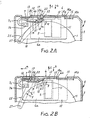
- the shutter 6 is adapted to move between the closed position (both openings 11 are out of register with both openings 5, whereby both openings 5 are closed by both shutter plates 6a) as shown in Figures 1 and 2A and the opening position shown in Figure 2B (both openings 11 are in register with both openings 5 whereby both openings 5 are opened) in directions designated by arrows a and b.
- the shutter 6 is forced to return to the closed position in the direction designated by the arrow b by means of a return spring 15 which is disposed between a spring securing slot 14a provided on the inside of the connection plate 6b and a spring securing slot 14b provided on the inside of the cartridge 4.
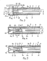
- the lock member 7 is formed of synthetic resin or the like, in which a spring action portion 7c curved in the form of a substantially circular arc between a free end 7a and a fixed end 7b is integrally provided.
- the lock member 7 is fixed to the cartridge 4 at the fixed end 7b.
- the free end 7a is provided with a lock recess 18 which is formed as a recess and locks a projection 17 provided on the inside of the connection plate 6b of the shutter 6 when the shutter 6 is returned to the closed position.
- the free end 7a is also provided with a guide groove 19 which guides the projection 17 when the shutter 6 is moved in the directions designated by the arrows a and b during opening and closing.
- the projection 17 is inserted deeply into the cartridge 4 through an opening 20.
- the depth A of the guide groove 19 is large with respect to the thickness B of each of the upper half 2 and the lower half 3.
- a slanted surface 21 Between the lock recess 18 and the bottom of the guide groove 19 is provided a slanted surface 21.
- a cutout 22 is provided in the shutter 6 at the position between the connection plate 6b and both shutter plates 6a. When the shutter 6 is returned to the closed position, the tip of the free end 7a of the lock member 7 can be disposed inside the cutout 22.
- a cutout 23 provided at the front end 4a of the cartridge 4 is adapted to be brought into registry with the cutout 22 of the shutter 6.
- FIG. 1 The structure of the disk cartridge when the disk cartridge is not in use is shown in Figure 1, wherein the shutter 6 is returned to the closed position by means of the return spring 15, and both openings 5 are closed by both shutter plates 6a. In this closed state, the projection 17 of the shutter 6 is secured by the lock portion 18 of the lock member 7, and the shutter 6 is locked at the closed position. Therefore, when the disk cartridge is not in use, the shutter 6 cannot be moved in the opening direction (the direction designated by the arrow a) unless the aforesaid lock 7 is released.
- the disk cartridge When the disk cartridge is inserted into a disk player (not shown), the disk cartridge is inserted into the disk player in the direction designated by an arrow c as shown in Figures 1 to 3.
- a shutter opening and closing pin 26 which is disposed at the tip of a shutter opening and closing lever 25 provided in the disk player is, as shown in Figure 2A, inserted into the cutout 22 of the shutter 6 from the direction designated by an arrow d.
- the free end 7a of the lock member 7 is pushed, and the free end 7a is deflected in the direction designated by an arrow e against the spring force produced by the spring action portion 7c.
- the lock portion 18 is released from the projection 17 of the shutter 6, whereby locking of the shutter 6 is released.
- both openings 5 are in register with both openings 11.
- the disk 1 is mounted onto a disk table (not shown) which is inserted into the opening 8, and a pair of upper and lower heads (not shown) are simultaneously inserted into both openings 5. Thereafter, the disk 1 is driven and rotated in the cartridge by the disk table, and the upper and lower recording surfaces of the disk 1 are selectively recorded or played by means of the heads.
- the projection 17 is guided by the guide groove 19 which has a sufficiently large depth A to eliminate instability during opening and closing of the shutter, and consequently the shutter 6 can be smoothly opened and closed.
- the lock member 7 is not limited to the described one made of synthetic resin, as it may be journaled relative to the cartridge 4, and biased by a return spring in the direction of the arrow g in Figures 2B.
- the head insertion opening 5 is opened and closed by the shutter 6 in the described embodiments, the head insertion opening 5 and the disk table insertion opening 8 may be simultaneously opened and closed by the shutter 6.
Landscapes
- Feeding And Guiding Record Carriers (AREA)
Applications Claiming Priority (2)
| Application Number | Priority Date | Filing Date | Title |
|---|---|---|---|
| US21744388A | 1988-07-11 | 1988-07-11 | |
| US217443 | 1988-07-11 |
Publications (2)
| Publication Number | Publication Date |
|---|---|
| EP0351159A2 true EP0351159A2 (de) | 1990-01-17 |
| EP0351159A3 EP0351159A3 (de) | 1990-03-07 |
Family
ID=22811101
Family Applications (1)
| Application Number | Title | Priority Date | Filing Date |
|---|---|---|---|
| EP89306967A Withdrawn EP0351159A3 (de) | 1988-07-11 | 1989-07-10 | Plattenkassette |
Country Status (2)
| Country | Link |
|---|---|
| EP (1) | EP0351159A3 (de) |
| JP (1) | JPH0216470U (de) |
Cited By (2)
| Publication number | Priority date | Publication date | Assignee | Title |
|---|---|---|---|---|
| EP0778567A3 (de) * | 1990-01-29 | 1997-11-05 | Dai Nippon Insatsu Kabushiki Kaisha | Plattenkassette |
| DE19719975B4 (de) * | 1996-05-14 | 2004-10-28 | Alps Electric Co., Ltd. | Scheibenkassette |
Citations (1)
| Publication number | Priority date | Publication date | Assignee | Title |
|---|---|---|---|---|
| EP0215958A1 (de) * | 1985-04-15 | 1987-04-01 | Sony Corporation | Plattenkassette |
-
1989
- 1989-07-10 EP EP89306967A patent/EP0351159A3/de not_active Withdrawn
- 1989-07-11 JP JP8161089U patent/JPH0216470U/ja active Pending
Patent Citations (1)
| Publication number | Priority date | Publication date | Assignee | Title |
|---|---|---|---|---|
| EP0215958A1 (de) * | 1985-04-15 | 1987-04-01 | Sony Corporation | Plattenkassette |
Cited By (2)
| Publication number | Priority date | Publication date | Assignee | Title |
|---|---|---|---|---|
| EP0778567A3 (de) * | 1990-01-29 | 1997-11-05 | Dai Nippon Insatsu Kabushiki Kaisha | Plattenkassette |
| DE19719975B4 (de) * | 1996-05-14 | 2004-10-28 | Alps Electric Co., Ltd. | Scheibenkassette |
Also Published As
| Publication number | Publication date |
|---|---|
| EP0351159A3 (de) | 1990-03-07 |
| JPH0216470U (de) | 1990-02-01 |
Similar Documents
| Publication | Publication Date | Title |
|---|---|---|
| US4573093A (en) | Disc cassette loading apparatus | |
| KR950008679B1 (ko) | 기록매체 수납용 케이스 | |
| EP0174111A2 (de) | Schliessmechanismus für eine Kassette | |
| JPS5830671B2 (ja) | フロッピィディスク駆動装置 | |
| US4614991A (en) | Cassette tape recording and/or reproducing apparatus | |
| EP0351160A2 (de) | Plattenhalterung | |
| JPS62138348U (de) | ||
| EP0351159A2 (de) | Plattenkassette | |
| JPH0142849Y2 (de) | ||
| US4953045A (en) | Cassette tape player with door operating mechanism | |
| JPS58166571A (ja) | カセツト装着装置 | |
| JPS63317486A (ja) | 情報担体のための保管ケース | |
| JP2565215B2 (ja) | ディスクカートリッジ | |
| JPS6215894Y2 (de) | ||
| US5068761A (en) | Disk cartridge with notch for locking a shutter | |
| KR100247781B1 (ko) | 광 디스크 기록 재생장치의 디스크 안착용 트레이 | |
| JP2937023B2 (ja) | ディスク装置 | |
| KR100197393B1 (ko) | 테이프 레코더의 해제 레버 | |
| KR890016533A (ko) | 음향 재생장치 | |
| JP2729674B2 (ja) | テーププレーヤにおけるスライド部片 | |
| JP2616501B2 (ja) | カセットローディング装置 | |
| JP2526420B2 (ja) | カセットロ―ディング装置 | |
| JPH0424507Y2 (de) | ||
| JPH059869B2 (de) | ||
| JPH0110748Y2 (de) |
Legal Events
| Date | Code | Title | Description |
|---|---|---|---|
| PUAI | Public reference made under article 153(3) epc to a published international application that has entered the european phase |
Free format text: ORIGINAL CODE: 0009012 |
|
| PUAL | Search report despatched |
Free format text: ORIGINAL CODE: 0009013 |
|
| AK | Designated contracting states |
Kind code of ref document: A2 Designated state(s): DE NL |
|
| AK | Designated contracting states |
Kind code of ref document: A3 Designated state(s): DE NL |
|
| 17P | Request for examination filed |
Effective date: 19900803 |
|
| 17Q | First examination report despatched |
Effective date: 19920416 |
|
| STAA | Information on the status of an ep patent application or granted ep patent |
Free format text: STATUS: THE APPLICATION IS DEEMED TO BE WITHDRAWN |
|
| 18D | Application deemed to be withdrawn |
Effective date: 19921027 |