EP0350933B1 - Bildsignalverarbeitungsvorrichtung für Strichkodebildsignale - Google Patents
Bildsignalverarbeitungsvorrichtung für Strichkodebildsignale Download PDFInfo
- Publication number
- EP0350933B1 EP0350933B1 EP89112876A EP89112876A EP0350933B1 EP 0350933 B1 EP0350933 B1 EP 0350933B1 EP 89112876 A EP89112876 A EP 89112876A EP 89112876 A EP89112876 A EP 89112876A EP 0350933 B1 EP0350933 B1 EP 0350933B1
- Authority
- EP
- European Patent Office
- Prior art keywords
- data values
- black
- bar code
- region
- data
- Prior art date
- Legal status (The legal status is an assumption and is not a legal conclusion. Google has not performed a legal analysis and makes no representation as to the accuracy of the status listed.)
- Expired - Lifetime
Links
Images


Classifications
-
- G—PHYSICS
- G06—COMPUTING; CALCULATING OR COUNTING
- G06K—GRAPHICAL DATA READING; PRESENTATION OF DATA; RECORD CARRIERS; HANDLING RECORD CARRIERS
- G06K7/00—Methods or arrangements for sensing record carriers, e.g. for reading patterns
- G06K7/10—Methods or arrangements for sensing record carriers, e.g. for reading patterns by electromagnetic radiation, e.g. optical sensing; by corpuscular radiation
- G06K7/10544—Methods or arrangements for sensing record carriers, e.g. for reading patterns by electromagnetic radiation, e.g. optical sensing; by corpuscular radiation by scanning of the records by radiation in the optical part of the electromagnetic spectrum
- G06K7/10821—Methods or arrangements for sensing record carriers, e.g. for reading patterns by electromagnetic radiation, e.g. optical sensing; by corpuscular radiation by scanning of the records by radiation in the optical part of the electromagnetic spectrum further details of bar or optical code scanning devices
- G06K7/10861—Methods or arrangements for sensing record carriers, e.g. for reading patterns by electromagnetic radiation, e.g. optical sensing; by corpuscular radiation by scanning of the records by radiation in the optical part of the electromagnetic spectrum further details of bar or optical code scanning devices sensing of data fields affixed to objects or articles, e.g. coded labels
- G06K7/10871—Methods or arrangements for sensing record carriers, e.g. for reading patterns by electromagnetic radiation, e.g. optical sensing; by corpuscular radiation by scanning of the records by radiation in the optical part of the electromagnetic spectrum further details of bar or optical code scanning devices sensing of data fields affixed to objects or articles, e.g. coded labels randomly oriented data-fields, code-marks therefore, e.g. concentric circles-code
-
- G—PHYSICS
- G06—COMPUTING; CALCULATING OR COUNTING
- G06K—GRAPHICAL DATA READING; PRESENTATION OF DATA; RECORD CARRIERS; HANDLING RECORD CARRIERS
- G06K7/00—Methods or arrangements for sensing record carriers, e.g. for reading patterns
- G06K7/10—Methods or arrangements for sensing record carriers, e.g. for reading patterns by electromagnetic radiation, e.g. optical sensing; by corpuscular radiation
- G06K7/10544—Methods or arrangements for sensing record carriers, e.g. for reading patterns by electromagnetic radiation, e.g. optical sensing; by corpuscular radiation by scanning of the records by radiation in the optical part of the electromagnetic spectrum
- G06K7/10821—Methods or arrangements for sensing record carriers, e.g. for reading patterns by electromagnetic radiation, e.g. optical sensing; by corpuscular radiation by scanning of the records by radiation in the optical part of the electromagnetic spectrum further details of bar or optical code scanning devices
- G06K7/1093—Methods or arrangements for sensing record carriers, e.g. for reading patterns by electromagnetic radiation, e.g. optical sensing; by corpuscular radiation by scanning of the records by radiation in the optical part of the electromagnetic spectrum further details of bar or optical code scanning devices sensing, after transfer of the image of the data-field to an intermediate store, e.g. storage with cathode ray tube
-
- G—PHYSICS
- G06—COMPUTING; CALCULATING OR COUNTING
- G06K—GRAPHICAL DATA READING; PRESENTATION OF DATA; RECORD CARRIERS; HANDLING RECORD CARRIERS
- G06K7/00—Methods or arrangements for sensing record carriers, e.g. for reading patterns
- G06K7/10—Methods or arrangements for sensing record carriers, e.g. for reading patterns by electromagnetic radiation, e.g. optical sensing; by corpuscular radiation
- G06K7/14—Methods or arrangements for sensing record carriers, e.g. for reading patterns by electromagnetic radiation, e.g. optical sensing; by corpuscular radiation using light without selection of wavelength, e.g. sensing reflected white light
- G06K7/1404—Methods for optical code recognition
- G06K7/1439—Methods for optical code recognition including a method step for retrieval of the optical code
- G06K7/1443—Methods for optical code recognition including a method step for retrieval of the optical code locating of the code in an image
-
- G—PHYSICS
- G06—COMPUTING; CALCULATING OR COUNTING
- G06K—GRAPHICAL DATA READING; PRESENTATION OF DATA; RECORD CARRIERS; HANDLING RECORD CARRIERS
- G06K7/00—Methods or arrangements for sensing record carriers, e.g. for reading patterns
- G06K7/10—Methods or arrangements for sensing record carriers, e.g. for reading patterns by electromagnetic radiation, e.g. optical sensing; by corpuscular radiation
- G06K7/14—Methods or arrangements for sensing record carriers, e.g. for reading patterns by electromagnetic radiation, e.g. optical sensing; by corpuscular radiation using light without selection of wavelength, e.g. sensing reflected white light
- G06K7/1404—Methods for optical code recognition
- G06K7/1439—Methods for optical code recognition including a method step for retrieval of the optical code
- G06K7/1456—Methods for optical code recognition including a method step for retrieval of the optical code determining the orientation of the optical code with respect to the reader and correcting therefore
Definitions
- the present invention relates to an image signal processing apparatus for processing an input image signal obtained by line-sequential scanning of a source image which includes one or more bar code labels, to read and decode the bar code.
- the invention relates to an image signal processing apparatus for processing such a bar code image signal, which will automatically ensure accurate reading and decoding of the bar code even if the bar code labels are arbitrarily positioned and inclined within the source image.
- Bar codes have been widely used in the prior art, in general for POS merchanidizing applications in supermarkets, etc.
- the bar code may be printed on adhesive labels, which are then attached to surfaces of respective articles which are to be sold, or may be directly printed on a surface of the article.
- the term "bar code label” is used for convenience of description to signify a printed bar code pattern, irrespective of whether the pattern has been directly printed on a surface of an article or has been printed on a separate label which is then attached to the article.
- the term “bar code label” should be understood to signify the entire label, which consists of an array of parallel bars and, generally, a line of numerals.
- bar code region signifies only the array of parallel bars in the bar code label.
- the bar code labels may be disposed at various arbitrary positions and inclinations upon the articles, and there may be two or more bar code labels closely mutually adjacent on the surface of each article.
- various proposals for bar code readers have been made in the prior art. THese generally are based upon scanning a bar code pattern in a plurality of different directions, to ensure that at least one correct scan (e.g.
- An image signal processing apparatus corresponding to the preamble of Claim 1 is known from JP-A- 5759 285.
- processing of data representing such a source image is executed to obtain data in which each bar code region is converted to a rectangular all-black region, of identical position and orientation to the original bar code region.
- background black regions in the background of the source image are also converted to corresponding black regions containing expanded numbers of black picture elements.
- the data thus obtained are subjected to contraction processing using a scanning window, to execute contraction of all of the black regions, to thereby substantially entirely eliminate the background black regions, and leave a black region corresponding to each bar code region, but of smaller size.
- the input data values representing the source image are stored in an image memory, at positions corresponding to respective picture elements in the source image.
- a first embodiment of the invention is applicable to bar code regions which are of rectangular elongated shape.
- the result of the aforementioned contraction processing is to leave a thin, straight elongated black region corresponding to each bar code region of the source image.
- the center position and slope of such an elongated black region can be easily computed, and from this information and the known length of the bar code region, a linear array of data values can be read out from the image memory, corresponding to a set of successive picture elements which lie along a central axis of elongation of the bar code, to thereby read the code data. These are then decoded.
- Another embodiment of the invention is applicable to bar code regions which are not substantially elongated.
- data representing the positions of the four corners of a resultant black region corresponding to a bar code region are computed.
- One or both of the central axes of the bar code region can thereby be computed, and the code data thereby read out from the image memory, and decoded.
- the invention provides an image signal processing apparatus for processing an input image signal representing successive data values of an array of picture elements of a source image containing at least one bar code region of rectangular shape, the array comprising successive scan lines each extending along a main scanning direction, with the scan lines successively arrayed along a secondary scanning direction, the apparatus comprising : bi-level conversion means for converting the data values of the input image signal to successive bi-level data values selectively indicating respective black and white states of the picture elements; image memory means for storing the bi-level data value; bar code region detection means for processing the bi-level data values to obtain bi-level data values representing a converted image containing a black region of substantially identical shape and orientation to the bar code region in the source image, and in which substantially all other black portions of the source image are eliminated to form a white background; bar code position detection means for receiving the data values from the bar code region detection means, to derive position coordinates representing a central axis and a center position of the black region, and for computing, based on a known length of the
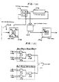
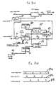
- Fig. 1(a) is a conceptual system block diagram of a first embodiment of an image signal processing apparatus according to the present invention.
- Numeral 1 denotes an input terminal for receiving a multi-level input image signal, which has been generated by raster scanning of a source image which contains at least one bar code region.
- Numeral 2 denotes a bi-level conversion section for converting the input image signal to a bi-level signal, consisting of successive data values which correspond to respective ones of an array of picture elements of the source image.
- Each of these bi-level data values is either a logic 1 or 0 value, corresponding to a black and white state respectively of a picture element.
- Numeral 5 denotes an image memory, for storing the bi-level data values produced from the bi-level conversion section 2 in a 2-dimensional array of addresses. Each address stores one bit, and the address array corresponds to the array of picture elements of the source image. Thus, each data value that is stored in the image data memory 5 can be designated for read-out from the memory by specifying the coordinates of the corresponding picture element in the source image.
- Numeral 3 denotes a bar code detection section, for processing the bi-level data values from the bi-level conversion section 2 to obtain data representing a converted image in which each bar code region is represented by a corresponding single full-black region, with the remainder of the converted image being a white background, with substantially all black regions other than those corresponding to bar code regions being eliminated.
- Numeral 4 denotes a bar code position detection section for deriving, from data representing a full-black region corresponding to a bar code region, produced from the bar code region detection section 3, the positions in the source image of a set of picture elements which extend continuously along a central axis of a bar code region, i.e. along the direction of elongation of that region.
- Numeral 6 denotes a bar code decoding section for reading out from the image memory 5 the data values corresponding to the aforementioned set of picture elements extending along the central axis of the bar code region, to thereby read the code data, and for decoding that data.
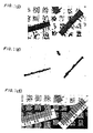
- Fig. 2(a) shows an example of a source image, in which two bar code regions (e.g formed by bar code labels which are attached to an article from which the source image is obtained), each of elongated rectangular shape, appear at arbitrary positions and arbitrary inclinations. These bar code regions (one of which is designated as A in Fig. 2(a)) are superimposed on a background region (B) which includes various arbitrary black-and-white patterns and pattern portions. In order to decode the bar code, it is necessary to execute data processing operations which are equivalent to:
- Fig. 2(b) illustrates the results of boundary line detection processing, which is applied to the bi-level data values produced from the bi-level conversion section 2, by the bar code region detection section 3. As shown, data are derived which represent a converted image in which only transitions between black and white regions of the source image appear.
- Fig. 2(c) illustrates the results of black region expansion processing, which is executed by the bar code region detection section 3 after the boundary line detection processing of Fig. 2(b), the processing being based upon executing a logic OR operation on successive sets of data values of the converted image of Fig. 2(b), within a scanning window of size M x M picture elements (i.e. data values). That is, if at least one data value within the scanning window is in the "1" (i.e. black) state, then the corresponding data value in the converted image of Fig. 2(c) is set to the black state.
- data are derived which represent a converted image in which the space between each pair of mutually adjacent boundary lines of the converted image of Fig.
- FIG. 2(b) is filled with black (i.e. 1 level) data values, if the distance between the pair of boundary lines is less than the predetermined value M (expressed as a number of picture elements).
- This predetermined value (whose magnitude is determined by the size of the aforementioned scanning window that is used in this processing) is made slightly greater than the maximum distance between any pair of mutually adjacent boundary lines within a bar code region.
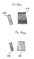
- Fig.. 3(a) illustrates a portion of an example of a bar code label. If the distance d1, (which is the width of a bar having maximum thickness, in the bar code) is greater than the distance d2, (which is the maximum distance between any two adjacent bars), then the aforementioned predetermined value is made slightly greater than d1.
- the data representing the converted image of Fig. 2(c) are subjected to black region contraction processing, to obtain data representing a converted image of the form shown in Fig. 2(e), with the processing results obtained in an intermediate stage being shown in fig 2(d).
- This is executed by again transferring successive data values of the converted image of Fig. 2(c) through a scanning window (which is substantially larger than that used for black region expansion), and applying the logic AND operation to the data values within the scanning window.
- the result of each such AND operation is set as the state of a corresponding data value in the converted image of Fig. 2(e). It can thus be understood that the black regions within the background in the converted image of Fig.
- the bar code position detection section 4 Based on the center position of the "skeleton” black region and the inclination of the center line, together with the (known) total length of a bar code region, the bar code position detection section 4 derives the respective coordinates of a linear array of picture elements which extend along the center line of the "skeleton" black region and a bar code region. These data values are then read out from the image data memory 5. This process of reading out these data values from the image data memory 5 is of course directly equivalent to scanning along the bar code region, to read the code contents.
- the data values thus read out from the image data memory 5, representing the bar code contents, are then supplied to the decoder section 6, to be decoded.
- the black region expansion section 12 executes processing, by applying the aforementioned logic OR processing of data values in an M x M scanning window (described in detail hereinafter), to obtain data values which represent a converted image in which the space between each mutually adjacent pair of boundary lines shown in Fig. 2(b) is "filled in” in black, if the separation between the pair is less than a predetermined value, as described above.
- the data values which thus result from processing by the black region expansion section 12, representing a converted image of the form shown in Fig. 2(c), are successiveively supplied to the black region contraction section 13, which executes the aforementioned black region contraction processing to obtain data representing a converted image of the form shown in Fig. 2(e), by executing logic AND operations on data values within an N x N scanning window (described in detail hereinafter).
- N is selected such as to ensure that a full-black "skeleton" of thin elongated shape will remain for each of the bar code regions.
- Data values representing one or more of these "skeleton" black region black regions are then supplied to a slope and center position computing section 9 in the bar code position detection section 4.
- the slope and center position computing section 9 then computes, for one or more of these black regions, the coordinates of the center position of that black region, as illustrated in Fig. 3(b).
- a "skeleton" black region 32 has been derived by the black region contraction section 13, from a bar code region designated by numeral 31.
- the center point Pc of the "skeleton" black region having coordinates (Xc, Yc), will be substantially identical to the center point of the corresponding bar code region.
- a straight line 33 which is aligned with the central axis of elongation of the "skeleton" black region will be substantially identical to the central axis of elongation of the bar code region 31.
- the center line 33 is suitable for scanning the bar code region 31 to read the bar code contents.
- the center line 33 is defined by the center point Pc (Xc, Yc) and by the inclination (designated in the following as k) of the center line. These are computed by the slope and center position computing section 9, and supplied to the read-out coordinates computing section 10.
- the read-out coordinates computing section 10 then computes the respective coordinates (i.e. with respect to the main scanning direction and the secondary scanning direction of the source image) of a linear array of picture elements which extend from a point P0 to a point P (L-1) shown in Fig. 3(b), i.e. from one end of the bar code region 31 to the opposite end, along the center line 33.
- the coordinates are then supplied to the image data memory 5, to read out the corresponding data values, and hence read the contents of the bar code, which are then supplied to the decoder section 6 to be decoded.
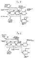
- Fig. 4 is an operation flow chart for illustrating the process of deriving the slope k and the center point coordinates (Xc, Yc) by the slope and center position computing section 9, based on the output data values produced from the bar code region detection section 3.
- initial values are set in a picture element counter n, an addition register A (for the x-coordinates of black picture elements, along the main scanning direction), an addition register B (for the x-coordinates of black picture elements, along the secondary scanning direction), an x.y addition register , and an x.x addition register D. Successive ones of the picture element data values produced from the black region contraction circuit are then inputted consecutively.
- step II a decision is made as to whether the last data value to be inputted represents a black picture element.
- step III the contents of the registers A, B, C and D are updated.
- step IV the slope k and the center position Pc coordinates (Xc, Yc) are computed.
- step II If in the decision step II, the black state is detected, then the contents of A, B, C and D are correspondingly updated in step III.
- step IV the values of the contents of the registers A, B, C and D are used to obtain the center line (as described hereinabove) of a "skeleton" black region corresponding to a bar code region, to obtain the center coordinates (Xc, Yc) for that bar code region.
- the processing executed by the read-out coordinates computing section 10 to obtain the coordinates of the linear array of picture element positions extending from point P0 to point P (L-1) , that have to be read out from the boundary line derivation section 7 in order to read and decode the bar code, is as follows.
- the read-out coordinates computing section 10 When the above set of coordinates have been computed by the read-out coordinates computing section 10, the corresponding data values are read out from the image data memory 5, as the contents of the bar code, and are supplied to the decoder section 6 to be decoded.
- a bar code region is separated from the background of the source image by converting the bar code region into a corresponding full-black region within a converted image, then the center position and the inclination of a central axis of that full-black region are derived, and used to, in effect, scan along the bar code region to read the code contents. It can be understood that this embodiment of the invention enables a bar code to be reliably decoded, even if the bar code is formed on one or more bar code labels that are disposed at arbitrary positions and aribtrary inclinations within a source image.
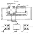
- Figs. 1(b), 1(c) and 1(d) are diagrams for describing the basic operation of respective scanning windows that are utilized in the bi-level variation detection section 11, black region expansion section 12 and black region contraction section 13.
- scanning windows are known in the prior art, described for example in U.S. patent No. 4,551,768, so that only a brief description will be given.
- 100a denotes an input memory for storing the picture element data values supplied from a preceding section, and is a 2-dimensional memory array (i.e. forms a 2-dimensional memory space).
- a logic processing circuit 100b executes logic processing for the respective one of the bi-level variation detection section 11, black region expansion section 12 and black region contraction section 13, and detailed description will be omitted.
- An output memory 100c stores data values obtained by processing by the logic processing circuit 100b. As in the case of the memory 100z, the memory 100c is a 2-dimensional memory array.
- a 2 x 2 scanning window is used.
- a set of data values d11, d12, d21, d22 are read out from the first two lines of data values stored in the memory 100a, and are processed by the logic processing circuit 100b (e.g. by executing a logic AND or OR operation on the data values), and the resultant data value is stored in a memory location D11 in the output memory 100c, i.e. in a memory location corresponding to the location D11 in the input memory 100a.
- a set of four picture element data values which are displaced with respect to the first-mentioned set by one position along the main scanning direction are read out from the memory 100a (i.e. the data values d12, d13, d22, d23), similarly processed by circuit 100b, and the result stored in location d12 of the output memory 100c (i.e. corresponding to the position d12 in the input memory 100a).
- Fig. 1(a)(e) 101a denotes an input memory for storing the bi-level data values that are produced from the bi-level conversion section 2, which is a 2-dimensional memory array.
- Numeral 101b denotes a logic processing circuit, having the configuration shown in Fig. 1 (f), i.e. formed of OR gates 101f to 101h, AND gates 101i to 101j, a NAND gate 101k, and an AND gate 101m.
- An output memory 101c stores results obtained from the logic processing circuit 101b, and is also a 2-dimensional memory array.
- a 4-picture element memory i.e.
- 4-data value) memory 101b corresponds to a 2 x 2 scanning window as described hereinabove.
- a shift register 101e functions as a 1-line memory. The operation of this circuit is as follows. Firstly, the bi-level data values from the bi-level conversion section 2 are successively stored in the input memory 101a. These data values are thereafter successively read out from the memory 101a, one at a time in synchronism with a clock signal (not shown in the drawings), to be stored at position D of the 4-picture element memory 101d.
- the data value which was held in location D of the 4-picture element memory 101d is transferred to the location C, while the data value which was at position C is transferred to the input of the one-line memory 101e, an output data value from the one-line memory 101e is transferred to position B of the 4-picture element memory 101d, and the value which as stored at the B position is transferred to the A position.
- the four values which are now held in the 4-picture element memory 101d are then supplied to the logic processing circuit 101b, and logic processing is then executed by the circuit shown in Fig. 1(f). That is, the logic sum (D n,n + D n+1,n + D n,n+1 + D n+1,n+1 ) is derived by the gates 101f to 101h, while the logic product (D n,n . D n+1,n . D n,n+1 . D n+1,n+1 ) is obtained by the gates 101i to 101k. The logic product of the outputs from the gates 101h and 101k is then obtained by the gate 101m.
- the resultant value from the gate 101m is then stored in the output memory 101c, at a position corresponding to the position D n,n of the input memory 101a.
- 102a denotes an input memory, of the type described for Fig. 101e, into which the processing results held in the output memory 101c of Fig. 101e are transferred and stored.
- 102b denotes a logic processing circuit, having the configuration shown in Fig. 101f, i.e. formed only of OR gates.
- An output memory 102c stores processed results produced from the logic processing circuit 102b, and is as described for the output memory 101c in Fig. 1 (e).
- a 64-picture element (i.e. 64 data value) memory 02d corresponds to an 8 x 8 scanning window.
- 102e denotes a set of seven shift registers, functioning as respective one-line memories.
- the operation of this circuit is as follows.
- the basic configuration is similar to that of the circuit of Fig. 1 (e), so that detailed description will be omitted.
- the logic processing circuit 102b derives the logic sum of all of the inputs applied thereto. If at least one of the data values which are currently held in the 8 x 8 scanning window (i.e. the memory 102d) is in the 1 state (indicating an all-black picture element state), then a 1 state output is produced from the logic processing circuit 102b. Otherwise, a 0 state output is produced.
- Each output result from the logic processing circuit 102b is stored in a location of the memory 102c, to thereby executed black region expansion processing as described hereinabove.
- 103a is an input memory, similar to that of Fig. 1(e), which receives and stores the processed results held in the output memory 102c of Fig. 1(g).
- a logic processing circuit 103b has the circuit configuration shown in Fig. 1(j), and is formed only of AND gates.
- each of the blocks I1 to I16 is formed as shown in Fig. 1(k), being formed of a set of AND gates.
- An output memory 103c stores the processing results obtained from the logic processing circuit 103b.
- a 1024 picture element memory 103d corresponds to a 32 x 32 scanning window, with the window configuration being as shown in fig 1(l).
- 103e denotes a set of 31 shift registers, functioning as respective one-line memories.
- Fig. 5 is a partial conceptual system block diagram of this embodiment.
- the second embodiment differs from the first embodiment with respect to the bi-level conversion section 2, and the remaining parts of the embodiment are identical to the first embodiment, so that further description will be omitted.
- the data values representing the source image that are applied to the input terminal 1 are converted to bi-level values by a bi-level conversion circuit 21, and the resultant bi-level values are supplied to a variable data reduction circuit 22.
- the variable data reduction circuit 22 functions to reduce the scanning line density and the density of picture elements in each scan line by equal amounts, with the amount of density reduction being variable in accordance with a density reduction value that is applied to an input terminal 23.
- variable density reduction value applied to the input terminal 23 designating the variable density reduction value applied to the input terminal 23 as A, density reduction by a factor A/B is produced, where B is a parameter that is fixedly set within the variable data reduction circuit 22. That is, for every B data values that are inputted, only a number A of these is selected to be outputted.
- the operation of the second embodiment is as follows.
- the conversion circuit 21 is a simply bi-level conversion circuit, utilizing a fixed threshold level, or a threshold level that varies in accordance with the input image signal level.
- the variable data reduction circuit 22 utilizes known technology, with the operation of that circuit being illustrated in the flow chart of Fig. 7.
- An example of a specific circuit within the variable data reduction circuit 22 for executing density reduction along the main scanning direction (i.e. for "thinning out” the number of data values in each scan line of the input image signal) is shown in Fig. 8(a), and a corresponding timing diagram in Fig. 8(b).
- a processing step 72 is executed in which a register, designated as M, is cleared.
- a processing step 74 the contents of register M are decremented by a fixed value A, and a decision is made as to whether the result is greater than or equal to zero. If so, a processing step 74 is executed, in which the aforementioned data value is skipped, i.e. is not outputted from the variable data reduction circuit 22.
- a decision step 75 a decision is made as to whether all of the data values of the source image have been processed. If all of the data values have been processed, then processing ends at step 76. If not, then operation returns to the step 73.
- the input image signal supplied to the input terminal 1 consists of successive digital data values, each corresponding to a specific picture element of the source image, which occur as successive sets of data values of successive scanning lines of the source image, with each set extending along the main scanning direction. Successive scanning lines extend along the secondary scanning direction.
- waveform (a) in Fig. 8(b) represents the input data values that are supplied to the variable data reduction circuit 22 from the bi-level conversion circuit 21, waveform (b) shows a timing pulse train which is synchronized with these data values, and waveform (c) shows a timing pulse train B which is phase-displaced from the timing pulses A.
- the bi-level data values from the bi-level conversion circuit 21 are supplied over a signal line 89a, and the output data values from the circuit of Fig. 8 appear on a signal line 89b.
- the terminal points B are supplied over a signal line 89c, and the timing pulses A are supplied over a signal line 89d.
- a secondary scanning synchronizing signal which is supplied on a signal line 89e consists of pulses which are respectively produced at the end of each set of data values correspondng to a line of picture elements (along the main scanning direction) of the source image.
- An AND gate 80 produces as output the logic product of the timing pulses B and an output signal from a register 84 (described hereinafter).
- An OR gate 81 generates the logic sum of the timing pulses A from signal line 89d and the output signal from the AND gate 80.
- a register 82 holds the fixed value A, while a register 83 holds the value B which is supplied from an external source, from a set of parallel input terminals 23, and which can be varied in order to vary the reduction factor A/B described above.
- a register 82 holds the value M, and is cleared each time a secondary scanning synchronizing pulse is applied over signal line 89e, and which latches the state of the output signal from a data selector 87 (described hereinafter) in response to an output pulse from the OR gate 81.
- the register 84 outputs, on a signal line 89f, the data held therein, together with a sign bit for that data.
- Register 84 also produces on a signal line 89g the sign bit alone.
- a subtractor 85 subtracts the contents of the register 82 from the contents of the register 84, and outputs the result.
- An adder 86 adds together the contents of the register 84 and the register 83, and outputs the result.
- the data selector 87 serves to select the output from the adder 86 to be outputted therefrom, if the sign bit that appears on the signal line 89g is in the 1 state, i.e. if the contents of the register 84 are negative. Otherwise, the data selector 87 selects the output from the subtractor 85 to be outputted therefrom.
- a data register 88 latches each input data value from the signal line 89a in response to an output pulse from the gate 80, and produces that data value as output on the signal line 89b.
- this circuit is as follows.
- the signal line 89g will be at the 0 logic level, so that the timing pulses B of signal line 89c will be inhibited from being produced from the gate 80.
- the contents of the data register 88 are not updated. Since the data selector 87 produces the output from the subtractor 85 in this case, the contents of the register 84 will become equal to (M-A), when a terminal point is applied on signal line 89d. If the contents of the register 84 become negative, then the signal line 89g will go to the 1 logic level, so that the timing pulses B from signal line 89c will be transferred by the gate 80, so that the contents of the data register 88 will be updated, i.e.
- the data selector 87 transfers the output from the adder 86, so that the contents of register 84 will become (M + B) when a timing pulse is applied on signal line 89c.
- the scan line density (and, correspondingly, the density of data values in each scan line) of the data that are supplied to the bar code region detection section 3 can be varied by adjusting the value B that is inputted from input terminals 23, and hence can be set to a fixed value of scan line density, it becomes possible to execute operation of the apparatus based on a fixed value of scan line density, irrespective of the scan line density of the input image signal that is supplied to the input terminal 1. That is to say, the apparatus can operate from input image signals having various different values of scan line density, without the need to change such image processing parameters as the scanning window size, etc.
- FIG. 6 is a partial conceptual system block diagram of this embodiment.
- the third embodiment differs from the first embodiment only with respect to the bi-level conversion section 2, and the remaining parts of the embodiment are identical to the first embodiment, so that further description will be omitted.
- the data values representing the source image that are applied to the input terminal 1 are converted to bi-level values by a bi-level conversion circuit 21, and the resultant bi-level values are supplied to a interpolation circuit 24.
- the resultant output from the interpolation circuit 24, comprising successive data values of the input image signal with additional interpolated data values inserted periodically by linear interpolation, is transferred to a variable data reduction circuit 22, which functions as described hereinabove for the second embodiment.
- the interpolation circuit 24 repetitively executes linear additive averaging computations on the input (multi-level) data values that are supplied to the input terminal 1, to obtain interpolated values, and so can be implemented in a simple manner.
- Fig. 9 shows an example of such interpolation, by a factor of 2. In Fig.
- the black region expansion section 12 executs black region expansion processing of all of the image outline data that are produced from the bi-level variation detection section 11.
- a fourth embodiment of the present invention will be described in which, instead of using all of these data, only a part of the data produced from the bi-level variation detection section 11 are selected to be used for black region expansion processing. This is achieved by utilizing a selective black region expansion section between the bi-level variation detection section 11 in place of the black region expansion section 12 shown in Fig. 1(a), for eliminating all data produced from the bi-level variation detection section 11 that cannot form part of a bar code region pattern and for executing black region expansion processing for the remaining data.
- the selective black region expansion section 12 employs an M x M scanning window (where the value M is determined in accordance with the maximum thickness of a bar in the bar code or the maximum spacing between adjacent bars, as for the M x M scanning window of the black region expansion section 12, described hereinabove), through which each of the data values produced from the bi-level variation detection section 11 are passed.
- M x M scanning window where the value M is determined in accordance with the maximum thickness of a bar in the bar code or the maximum spacing between adjacent bars, as for the M x M scanning window of the black region expansion section 12, described hereinabove
- white state value is produced as a data value corresponding to the scanning window contents, i.e. the window contents are not used in black region expansion processing. If the current set of data values in the scanning window does not match any of these predetermined patterns, then as for the black region expansion section 12 described above, the OR logic sum of the states of the data values in the M x M window is produced as a data value corresponding to the window contents, to thereby execute black region expansion processing as for the first embodiment described above.
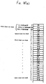
- Fig. 10 shows various examples of such predetermined patterns, contained in an M x M scanning window, which in this example is a 7 x 7 square window. None of the patterns in Fig. 10 can occur as part of a bar code region outline.
- a decision is made to eliminate the contents of the current scanning window from the black region expansion processing if the center data value of the window is in the 1 state, while at least five of each of the A and B data values in the window are in the 1 state, since this indicates that the contents of the scanning window cannot form part of a bar code region outline. In this case, a 0 output is produced in response to the dw contents.
- the contents of the 7 x 7 scanning window are detected by the selective black region expansion section 12 as conforming to a pattern other than any of those shown in Fig. 10, then this indicates a possibility that the scanning window contents may form part of a bar code region outline, and hence the logic sum of the data values within the scanning window is obtained, to form part of the data that are subsequently transferred to the black region contraction section 13 for black region contraction processing as described hereinabove.
- the amount of background black regions which must be eliminated by the black region contraction processing executed by the black region contraction section 13 is substantially reduced, thereby enabling more effective elimination of background "noise" regions in the data produced from the black region contraction section 13 and enabling a higher speed of operation.
- Fig. 11 is a partial system block diagram of a fifth embodiment of an image signal processing apparatus according to the present invention, with only the constituent blocks of the region derivation section 8 being shown. The fifth embodiment differs from the first embodiment of Fig.
- the black region contraction section 13 is preceded by a data reduction circuit 230, which substantially reduces the amount of data that are transferred from the black region expansion section 12 to the black region contraction section 13.
- This data reduction circuit 230 functions by "thinning out” the number of data values in each scan line of the data supplied from the black region expansion section 12 (e.g. by transferring to the black region contraction section 13 only one out of every m data values that are supplied from from the black region expansion section 12, where m is a fixed integer) and similarly “thinning out” the scanning lines of the data, (by the same reduction factor m), to thereby achieve data reduction by equal proportions in the main scanning direction and the secondary scanning direction.
- variable data reduction circuit 22 This function is similar to that of the variable data reduction circuit 22 described hereinabove with reference to Figs. 5 and 6, so that detailed description will be omitted.
- the data reduction circuit 230 of the fifth embodiment need only produce a fixed amount of data reduction, i.e. need not be capable of varying the degree of reduction, such as is possible with the variable data reduction circuit 22. Designating the combined reduction factor that results from this data reduction circuit 230 in conjunction with the contraction produced by the contraction section 13 as R, and the width of a bar code region (i.e.
- this data reduction circuit 230 must be determined such that the combined degree of reduction that is produced by reduction circuit 230 together with the reduction produced by the black region contraction section 13 must not reduce the width of a bar code region below a certain minimum value, e.g. to ensure that "skeleton" black region black regions corresponding to the bar code regions will remain, as shown in Fig. 2(e), while most of the extraneous background black regions are eliminated.
- the size of the scanning window used in the black region contraction section 13 can be reduced, and hence the circuit configuration of the black region contraction section 13 can be simplified and the speed of operation increased.
- Fig. 12 is a partial system block diagram of the sixth embodiment, with only the constituent blocks of the region derivation section 8 being shown.
- This embodiment differs from the fifth embodiment of Fig. 11 in that the data reduction circuit 230 is preceded by a data contraction circuit 231, which executes contraction of data that are transferred from the black region expansion section 12 to the 230.
- This data contraction circuit 231 functions in a similar manner to the black region contraction section 13 described hereinabove, but utilizes an m x m scanning window (where l/m is the reduction factor produced by the contraction section 230 as described above), with logic AND processing being applied to the window contents.
- the data reduction circuit 230 executes data reduction (i.e.
- Fig. 13(a) shows an example of a converted image, represented by the output data produced from the black region expansion section 12.
- 232 denotes full-black region which corresponds to a bar code region in the source image.
- 233 denotes a pattern of successively adjacent black regions which has been accidentally produced by the black region expansion section 12, e.g. as a result of some pattern in the source image, unrelated to the bar code. If this image data is directly supplied to the 230, so that "thinning-out" in the main scanning direction and secondary scanning direction is executed (i.e.
- the bar code position detection section of the first embodiment described above is suitable for use with bar code regions which are of substantially elongated rectangular shape.
- a seventh embodiment of an image signal processing apparatus will be described, referring to Figs. 14 to 21, which is applicable to bar code regions which are of various rectangular shapes, including square shaped regions.
- the bar code position detection section 4 of the first embodiment shown in Fig. 1(a) is replaced by a bar code position detection section 4a.
- the remaining system blocks of this embodiment are identical to those of Fig. 1(a), and further description of these will be omitted.
- the bar code position detection section 4a differs from the detection section 4 of Fig.
- a boundary coordinate detection section 101 for detecting the main scanning direction coordinates of respective terminal positions of sets of successively mutually adjacent black picture elements (i.e. corresponding 1 state data values) which extend along the main scanning direction, to form full-black regions within respective scanning lines of the image data.
- Such sets of mutually adjacent black picture elements extending within a single scan line will be referred to as black row blocks, since each scan line of picture elements is represented as a horizontal row in the drawings.
- numeral 102 denotes a linkage judgement section, for judging whether black row blocks are mutually linked along the secondary scanning direction, i.e.
- a terminal point coordinate detection section 103 detects those picture elements within a black region (formed of a plurality of black row blocks mutually linked in the secondary scanning direction) which have coordinates that are at maximum and minimum positions along the main scanning direction and the secondary scanning direction (i.e. picture elements which are positioned at the uppermost or lowermost positions, or rightmost or leftmost positions of a black region, as viewed in the drawings).
- a read-out coordinate computing section 104 computes readout position coordinates, for reading out bar code region data values from stored image data values.
- the boundary coordinate detection section 101 detects boundary coordinates of respective black row blocks, along the main scanning direction, which are represented in the contracted image data produced from the black region contraction section 13. Specifically, for each picture element data value, the boundary coordinate detection section 101 computes the exclusive-OR value of the x-coordinate of that picture element in conjunction with that of the immediately preceding picture element (i.e. the picture element whose data value is produced in the immediately preceding processing clock period). If the result is logic 1, then this indicates that a boundary coordinate has been detected.
- Fig. 15(a) illustrates various terminal picture element positions (shown as cross-hatched squares) of respective black row blocks. The coordinates of each such terminal picture element will be referred to as boundary coordinates of a black row bloc.
- each black row block there is a single secondary scanning direction boundary coordinate (i.e. y-coordinate) and a pair of main scanning direction boundary coordinates (i.e. x-coordinates). These boundary coordinates are stored in respective registers with the arrangement illustrated in Fig. 15(b).
- the data that are supplied to the bar code position detection section 4a are first processed by the boundary coordinate detection section 101 to detect each of the black row blocks that are represented in the data. Each time that a black row block is detected, the y-coordinate of the black and the initial x-coordinate and terminating x-coordinate of the block (respectively indicated as Xs, Xe in Fig. 15(b)) are stored in a register. Next, when this processing has been completed for all of the image data, the linkage judgement section 102 executes processing to determine those of the black row blocks which are mutually linked to form one or more black regions, e.g. the first, second and third black regions shown in Fig. 15(a).
- Fig. 16 is an operating flow chart for illustrating the processing that is executed by the linkage judgement section 102.
- each of the black regions is detected as a succession of black row blocks, i.e. which are successively detected (along the secondary scanning direction) as being linked with that black region.
- the y-coordinate of the most recent black row block to have been detected a linked to a black region is designated as KY(j)
- the initial x-coordinate of that black row block is designated as KXs(j)
- the terminating x-coordinate of the black row block is designated as KXe(j)
- j takes the successive values 1, 2, 3,....
- n The count in a counter register that is used to count successive black regions is designated as n, and the contents of an attribute flag which designates the black region to which the i th black row block belongs are designated as f(i), where i takes the values 1, 2, 3, alone
- LY(j) and LXs(j) and LXe(j) are each set to zero.
- step 122 the count n is initialized, and in step 123 the boundary coordinates Y(i), Xs(i) and Xe(i) for the i th black row block are read out from one of the registers shown in Fig. 15(b).
- a linkage judgement set of steps 124 a decision is made as to which of the black regions the i th black row block belongs.
- This set of steps 124 will be described in detail referring to the drawings.
- successive linkage judgement decision are made for each of the black row blocks as to the respective black regions to which the black row blocks belong.
- step 130 the black region counter n is incremented by one, in step 131 the attribute flag f(i) is set to n, and in step 132, new values of boundary coordinates LY(n), LXs(n) and LXe(n) are registered for this new black region, i.e. as the n th black region, in the register whose contents are shown in Fig. 15(b).
- a judgement is made as to whether the i th black row block is linked along the secondary scanning direction to a previously registered black region (i.e. to find if the y-coordinate of that row block immediately follows the y-coordinate of the last row block in the k th black region, along the secondary scanning direction). If a NO decision is reached in step 126, then this judgement operation is repeated for another black region, by incrementing k. If a YES decision is reached in step 126, then operation advances to step 127 in which is made as to whether the i th black row block is linked along the main scanning direction to a previously registered black region.
- Such linkage of black row blocks along the main scanning direction can be of four types, as illustrated in Fig. 17(a) to (d). For each of these conditions, the following relationships are both satisfied: Xs(i) ⁇ LXe(k) and, Xe(i) > LXe(k) If a YES decision is reached in step 127, then this indicates that the i th black row block belongs to the k th black region, and so the attribute flag f(i) is set to the value k, and in step 129 the updated boundary coordinates LY(n), LXs(n) and LXe(k) are registered for the k th black region.
- the terminal point coordinate detection section 103 in Fig. 14 serves to detect, for each of the black regions shown for example in Fig. 18, a point (i.e. a picture element position) Ymin having the smallest coordinate value of that black region in the secondary scanning direction, a point Y max , having the maximum value of secondary scanning direction coordinate, a point x min , having the the smallest coordinate value of that black region in the main scanning direction, and a point X max , having the maximum value of main scanning direction coordinate.
- These points Y min , Y max , X min and X max of a black region will be referred to as the terminal points of that region.
- the terminal point coordinate detection section 103 derives these coordinate values based on the boundary coordinates of the black row blocks constituting that black region, which have been obtained by the processing described above, executed by the linkage judgement section 102.
- Fig. 19 is a flow chart of the processing which is executed to obtain these terminal points for each of the black regions, based on the attributes represented by the attribute flag f(i) obtained for the i th black row block as described above.
- initial values are is set in a terminal point coordinate register, for each of the black regions that are represented by the output data from the black region contraction section 13 (e.g. the three black regions in Fig. 18.
- the contents of the attribute flag of the i th black row block are set as a value P.
- a decision is made as to whether Y(i) is greater than the y-coordinate of point Y min .
- step 144 a decision is made as to whether Y(i) is less than the y-coordinate of point Y max .
- step 145 a decision is made as to whether Xs(i) is less than the x-coordinate of X min .
- step 146 a decision is made as to whether Xe(i) is greater than the x-coordinate of X max .
- steps 147, 148, 149 and 150 the y and x-coordinates of the points Y min , Y max , X min and X max are respectively updated.
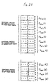
- step 141 initial values such as those shown in Fig. 20 are set into terminal point coordinate registers for the respective black regions.
- the minimum value of secondary scanning direction coordinate of that region is set as the y-coordinate of the point Y min of that region, and the maximum value of main scanning direction coordinate of the black region is set as the x-coordinate of the point X min of that black region.
- Fig. 17 shows an example of these coordinate values for X min , Y min etc for various black regions (indicated as the first black region, second black region, etc), stored in respective coordinate registers.
- the y-coordinate of the point Y min for that region is the smallest value of y-coordinate (i.e. secondary scanning direction coordinate) within that region, and is indicated in Fig. 21 as a value S.
- the x-coordinate of the point X min for a black region is the smallest value of x-coordinate (i.e. main scanning direction coordinate) within that region, and is indicated as M in Fig. 21.
- step 142 a value specifying the particular black region to which the i th black row block belongs, is set as P.
- step 143 a magnitude comparison is made between Y(i) and the y-coordinate of the point Y min (P). If a YES decision is obtained, then step 147 is executed in which the x-coordinate and y-coordinate of Y min (P) are updated.
- steps 144, 145, and 146 magnitude comparisons are respectively executed between the y-coordinate of Y max (P) and Y(i), between the x-coordinate of X min (P) and Xs(i), and between the x-coordinate of X max (P) and Xe(i). Respective YES decisions from these comparison steps result in coordinate updating being executed in steps 148, 149 and 150.
- Fig. 21 is a diagram for illustrating the derivation of position relationships for executing reading of the bar code data with this embodiment.
- Numeral 161 denotes a the outline of a black region that is represented in the output data from the black region contraction section 13, corresponding to a bar code region that has been contracted in size.
- the original bar code region is indicated by numeral 163.
- 162 denotes a straight line which is a bar code read-out position line that passes through the center point Pc, as described hereinabove for the preceding embodiments.
- the read-out coordinate computing section 104 computes the coordinates (Xc, Yc) of a center point Pc of the bar code region, and the slope k of the line 162, based upon the terminal points Y min (x1, Y1), X min (x2, y2), Y max (x3, y3) and Y min (x4, y4), which are derived by the terminal point coordinate detection section 103 as described above.
- a set of data values stored in the image data memory 5 which correspond to positions along the line 162 are then read out from the image data memory 5, to in effect scan along the bar code and thereby read the code data.
- the read-out coordinate computing section 104 computes the center point coordinates (Xc, Yc) and the slope k (where the term "slope", as for the first embodiment, signifies the tangent of the angle between line 162 and the main or secondary scanning direction) from the following equations.
- a bar code region has an elongated rectangular shape, with the axis of elongation being perpendicular to the direction of elongation of the bars.
- a straight line A-A′ is derived, passing through the bar code region center point and lying along the axis of elongation of the bar code region, for reading out the data values of picture elements which lie along that straight line and thereby reading the bar code contents.
- the bar code region is shaped as shown in Fig. 22(b), with the axis of elongation being aligned with the direction of elongation of the bars.
- a bar code region of the shape shown in Fig. 22(b) can be read by first deriving a straight line corresponding to the axis of elongation A-A′ as described for the first embodiment, then deriving a line B-B′ which passes through the center point of the bar code region and is perpendicular to line A-A′.
- the bar code data can then be read by reading out from the image data memory 5 the data values of picture elements which line along that line B-B′, within the bar code region.
- the bar code region may be of substantially square shape, as shown in Fig. 22(c).
- each of the embodiments of the invention operates under overall control that is executed by a microprocessor. Since such control is now very commonly utilized, description has been omitted in the specification.
- An apparatus for receiving input data values representing an array of picture elements of a source image containing one or more bar code regions whereby the input data values are converted to bi-level values representing black or white states which are stored in an image memory, while in addition the bi-level values are processed to obtain data representing an image in which a "skeleton" central portion of the bar code region appears as an all-black region, while background black regions are eliminated.
- a central position and the slope of a central axis of the bar code region are computed based on that "skeleton" region, and data values in the image memory which conform to the central axis are then read out, to read the bar code data.
Claims (11)
- Bildsignal-Verarbeitungseinrichtung zum Verarbeiten eines eingegebenen Bildsignals, das aufeinanderfolgende Datenwerte für eine Anordnung von Bildelementen eines Ursprungsbilds darstellt, welches mindestens einen Bereich in Rechteckform enthält, wobei die Anordnung aufeinanderfolgende Abtastlinien enthält, die sich jeweils in einer Hauptabtastrichtung erstrecken und die aufeinanderfolgend in einer Unterabtastrichtung aufgereiht sind, wobei die Verarbeitungseinrichtung
eine Binär-Umsetzeinrichtung (2) zum Umsetzen der Datenwerte des eingegebenen Bildsignals in aufeinanderfolgende binäre Datenwerte, die selektiv jeweilige Schwarz- und Weißzustände der Bildelemente anzeigen,
eine Bildspeichereinrichtung (5) zum Speichern der binären Datenwerte und
eine Bereicherfassungseinrichtung (3) zum Verarbeiten der binären Datenwerte für das Erhalten von binären Datenwerten aufweist, die ein umgeformtes Bild darstellen, welches einen Schwarzbereich mit im wesentlichen gleicher Form und Ausrichtung wie der Bereich in dem Ursprungsbild enthält und in welchem im wesentlichen alle anderen schwarzen Teile des Ursprungsbilds beseitigt sind, um einen weißen Hintergrund zu formen,
dadurch gekennzeichnet, daß die Bereiche Strichcodebereiche sind und daß die Verarbeitungseinrichtung ferner
eine Strichcodelage-Erfassungseinrichtung (4), die die Datenwerte aus der Bereicherfassungseinrichtung aufnimmt, um Ortskoordinaten abzuleiten, die eine Mittelachse und eine Mitte des Schwarzbereichs darstellen, und die aufgrund einer bekannten Länge des Strichcodebereichs auf der Mittelachse und aufgrund der Mitte jeweilige Auslesekoordinaten einer linearen Anordnung von Bildelementen berechnet, die sich entlang der Mittelachse in dem Strichcodebereich erstreckt, und
eine Decodiereinrichtung (6) aufweist, die aus der Bildspeichereinrichtung jeweilige binäre Datenwerte ausliest, die der linearen Anordnung von Bildelementen entsprechen, und die diese binären Datenwerte zum Erhalten von Daten für den Strichcodebereich decodiert. - Bildsignal-Verarbeitungseinrichtung nach Anspruch 1, in der die Binär-Umsetzeinrichtung
eine Binär-Umsetzschaltungseinrichtung zum Umsetzen von aufeinanderfolgenden Datenwerten des eingegebenen Bildsignals in jeweilige binäre Datenwerte und
eine Datenverdichtung-Schaltungseinrichtung (230) aufweist, die durch periodisches Weglassen von binären Datenwerten eine Verringerung der Dichte der durch die binären Datenwerte dargestellten Abtastlinien in einem steuerbar verändertem Ausmaß ausführt, um dadurch der Bildspeichereinrichtung und der Strichcodebereicherfassungseinrichtung Daten mit einem fest vorgegebenen Wert der Abtastliniendichte zuzuführen. - Bildsignal-Verarbeitungseinrichtung nach Anspruch 1, bei der die Binär-Umsetzeinrichtung
eine Interpolierschaltungseinrichtung, die interpolierte Datenwerte berechnet und in die aufeinanderfolgenden Datenwerte des eingegebenen Bildsignals einfügt, um Datenwerte mit einer hohen Datendichte zu erzeugen,
eine Binär-Umsetzschaltungseinrichtung zum Umsetzen aufeinanderfolgender Datenwerte aus der Interpolierschaltungseinrichtung in aufeinanderfolgende binäre Datenwerte und
eine Datenverdichtung-Schaltungseinrichtung (230) aufweist, die durch periodisches Weglassen von binären Datenwerten eine Verringerung der Dichte der durch die binären Datenwerte dargestellten Abtastlinien in einem steuerbar veränderten Ausmaß ausführt, um dadurch der Bildspeichereinrichtung und der Strichcodebereicherfassungseinrichtung Daten mit einem fest vorgegebenen Wert der Abtastliniendichte zuzuführen. - Bildsignal-Verarbeitungseinrichtung nach Anspruch 1, in der die Strichcodebereicherfassungseinrichtung
eine Grenzlinienableiteinrichtung, die die binären Datenwerte aus der Binär-Umsetzeinrichtung zu binären Datenwerten verarbeitet, die ein umgeformtes Bild darstellen, in welchem die Grenzen zwischen schwarzen und weißen Bereichen des Ursprungsbilds als schwarze Grenzlinien auf weißem Hintergrund abgebildet sind,
eine Schwarzbereich-Erweiterungseinrichtung (12), die die binären Datenwerte aus der Grenzlinienableiteinrichtung zu binären Datenwerten verarbeitet, die ein umgeformtes Bild darstellen, in welchem zwischen einander gegenüberliegenden Grenzlinien liegende Bereiche, die nicht eine vorbestimmte maximale Breite überschreiten, mit schwarzen Bildelementen gefüllt sind, und
eine Schwarzbereich-Verengungseinrichtung (13) aufweist, die die binären Datenwerte aus der Schwarzbereich-Erweiterungseinrichtung zu binären Datenwerten verarbeitet, die ein umgeformtes Bild darstellen, in welchem die Schwarzbereiche des von der Schwarzbereich-Erweiterungseinrichtung erzeugten umgeformten Bildes hinsichtlich der Größe in einem vorbestimmten Ausmaß geschrumpft sind. - Bildsignal-Verarbeitungseinrichtung nach Anspruch 4, in der
die Grenzlinien-Ableiteinrichtung (7) eine als ein erstes Abfragefenster zusammengestellte logische Schaltung, eine Einrichtung zum aufeinanderfolgenden Übertragen von aufeinanderfolgenden der von der Binär-Umsetzeinrichtung erzeugten binären Datenwerte durch das erste Abfragefenster hindurch und eine logische Verarbeitungsschaltungeinrichtung zum Erzeugen der logischen Antivalenzsumme der gegenwärtigen Datenwerte in dem ersten Abfragefenster als ein Datenwert des von der Grenzlinien-Ableiteinrichtung erzeugten umgeformten Bildes aufweist,
die Schwarzbereich-Erweiterungseinrichtung (12) eine als ein zweites Abfragefenster zusammengestellte logische Schaltung, eine Einrichtung zum aufeinanderfolgenden Übertragen von aufeinanderfolgenden der von der Binär-Umsetzeinrichtung erzeugten binären Datenwerte durch das zweite Abfragefenster hindurch und eine logische Verarbeitungsschaltungseinrichtung zum Erzeugen der logischen ODER-Summe der gegenwärtigen Datenwerte in dem zweiten Abfragefenster als ein Datenwert des von der Schwarzbereich-Erweiterungseinrichtung erzeugten umgeformten Bildes aufweist und
die Schwarzbereich-Verengungseinrichtung (13) eine als ein drittes Abfragefenster zusammengestellte logische Schaltung, eine Einrichtung zum aufeinanderfolgenden Übertragen von aufeinanderfolgenden der von der Schwarzbereich-Erweiterungseinrichtung erzeugten binären Datenwerte durch das dritte Abfragefenster hindurch und eine logische Verarbeitungsschaltungseinrichtung zum Erzeugen des logischen UND-Produkts der gegenwärtigen Datenwerte in dem dritten Abfragefenster als ein Datenwert des von der Schwarzbereich-Verengungseinrichtung erzeugten umgeformten Bildes aufweist. - Bildsignal-Verarbeitungseinrichtung nach Anspruch 5, in der die Schwarzbereich-Erweiterungseinrichtung (12) ferner eine Einrichtung aufweist, die den gegenwärtigen Inhalt des zweiten Abfragefensters mit einem jeden von einer Vielzahl von vorbestimmten Mustern vergleicht und die dann, wenn der gegenwärtige Inhalt irgendeinem der Muster entspricht, auf unbedingte Weise einen Ausgabedatenwert erzeugt, der den weißen Bildelementzustand darstellt.
- Bildsignal-Verarbeitungseinrichtung nach Anspruch 1, in der die Strichcodelage-Erfassungseinrichtung (4)
eine Neigungs- und Mittenberechnungseinrichtung (9) zum Berechnen jeweiliger Koordinaten einer Mitte des Schwarzbereichs, der einem Strichcodebereich in dem umgeformten Bild entspricht, das durch die von der Strichcodebereich-Erfassungseinrichtung erzeugten Datenwerte dargestellt ist, und eines Wertes, der eine Schräglage der Mittelachse in bezug auf die Hauptabtastrichtung oder die Unterabtastrichtung darstellt, und
eine Auslesekoordinaten-Berechnungseinrichtung (10) aufweist, die aufgrund des Schräglagewertes, der Mittenkoordinaten und der bekannten Länge des Strichcodebereichs die Auslesekoordinaten der sich entlang der Mittelachse in dem Strichcodebereich erstreckenden linearen Anordnung von Bildelementen berechnet. - Bildsignal-Verarbeitungseinrichtung nach Anspruch 7, in der die Neigungs- und Mittenberechnungseinrichtung (9) eine Einrichtung zum Erfassen einer ersten, einer zweiten, einer dritten und einer vierten Stelle in dem Schwarzbereich aufweist, der einem Strichcodebereich in dem umgeformten Bild entspricht, das durch die von der Strichcodebereich-Erfassungseinrichtung erzeugten Datenwerte dargestellt ist, wobei die erste, die zweite, die dritte und die vierte Stelle jeweils einen längs der Hauptabtastrichtung gemessenen minimalen KOordinatenwert, einen längs der Hauptabtastrichtung gemessenen maximalen Koordinatenwert, einen längs der Unterabtastrichtung gemessenen minimalen Koordinatenwert und einen längs der Unterabtastrichtung gemessenen maximalen Koordinatenwert haben, und in der die Auslesekoordinaten-Berechnungseinrichtung (10) die Auslesekoordinaten aufgrund der für die erste, die zweite, die dritte und die vierte Stelle in dem Schwarzbereich jeweils ermittelten Hauptabtastrichtung- und Unterabtastrichtung-Koordinatenwerte berechnet.
- Bildsignal-Verarbeitungseinrichtung nach Anspruch 7, bei der der Strichcodebereich in dem Ursprungsbild im wesentlichen entlang der Mittelachse langgestreckt ist und in der der Schwarzbereich, der entsprechend einem Strichcodebereich in dem umgeformten Bild erscheint, das durch die von der Strichcodebereich-Erfassungseinrichtung (3) erzeugten Datenwerte dargestellt ist, im wesentlichen als eine Anordnung von dünnen durchgehenden Linien von Schwarzzustand-Bildelementen geformt ist und in der der Wert, der die Schräglage der Mittelachse des Strichcodebereichs darstellt, als ein die Schräglage der Linienanordnung darstellender Wert erhalten wird und die Mitte als Mitte der Linienanordnung erhalten wird.
- Bildsignal-Verarbeitungseinrichtung nach Anspruch 1, in der die Strichcodebereich-Erfassungseinrichtung
eine Grenzlinien-Ableiteinrichtung (7) zum Verarbeiten der binären Datenwerte aus der Binär-Umsetzeinrichtung zu binären Datenwerten, die ein umgeformtes Bild darstellen, in welchem die Grenzen zwischen schwarzen und weißen Bereichen des Ursprungsbilds als schwarze Grenzlinien auf weißem Hintergrund gebildet sind,
eine Schwarzbereich-Erweiterungseinrichtung (12), die die binären Datenwerte aus der Grenzlinien-Ableiteinrichtung zu binären Datenwerten verarbeitet, die ein umgeformtes Bild darstellen, in dem zwischen einander gegenüberliegenden Grenzlinien liegende Bereiche, die nicht eine vorbestimmte maximale Breite überschreiten, mit schwarzen Bildelementen gefüllt sind,
eine Datenverdichtungs-Schaltungseinrichtung (230), die einen vorbestimmten Anteil der von der Schwarzbereich-Erweiterungseinrichtung erzeugten Datenwerte beseitigt und die restlichen Datenwerte abgibt, und
eine Schwarzbereich-Verengungseinrichtung (13) aufweist, die die von der Datenverdichtungs-Schaltungseinrichtung erzeugten binären Datenwerte zu binären Datenwerten verarbeitet, die ein umgeformtes Bild darstellen, in welchem die Schwarzbereiche eines durch die von der Datenverdichtungs-Schaltungseinrichtung erzeugten Datenwerte dargestellten umgeformten Bildes hinsichtlich der Größe in einem vorbestimmten Ausmaß geschrumpft sind. - Bildsignal-Verarbeitungseinrichtung nach Anspruch 1, in der die Strichcodebereich-Erfassungseinrichtung
eine Grenzlinien-Ableiteistrichtung, die die binären Datenwerte aus der Binär-Umsetzeinrichtung zu binären Datenwerten verarbeitet, die ein umgeformtes Bild darstellen, in welchem die Grenzen zwischen schwarzen und weißen Bereichen des Ursprungsbilds als schwarze Grenzlinien auf weißem Hintergrund geformt sind,
eine Schwarzbereich-Erweiterungseinrichtung (12), die die binären Datenwerte aus der Grenzlinien-Ableiteinrichtung zu binären Datenwerten verarbeitet, die ein umgeformtes Bild darstellen, in welchem zwischen einander gegenüberliegenden Grenzlinien liegende Bereiche, die nicht eine vorbestimmte maximale Breite überschreiten, mit schwarzen Bildelementen gefüllt sind,
eine Datenkontraktionseinrichtung (231), die als Abfragefenster zusammengestellte logische Schaltungen, eine Einrichtung zum aufeinanderfolgenden Übertragen von jeweils von der Schwarzbereich-Erweiterungseinrichtung erzeugten Datenwerten durch das Abfragefenster hindurch und eine logische Verarbeitungsschaltungseinrichtung zum Erzeugen des logischen UND-Produktes des gegenwärtigen Inhalts des Abfragefensters als Ausgabedatenwert enthält,
eine Datenverdichtungs-Schaltungseinrichtung (230), die einen vorbestimmten Anteil der von der Datenkontraktionseinrichtung erzeugten Datenwerte beseitigt und die restlichen Datenwerte abgibt, und
eine Schwarzbereich-Verengungseinrichtung (13) aufweist, die die von der Datenverdichtungs-Schaltungseinrichtung erzeugten binären Datenwerte zu binären Datenwerten verarbeitet, die ein umgeformtes Bild darstellen, in welchem Schwarzbereiche eines durch die von der Datenverdichtungs-Schaltungseinrichtung erzeugten Datenwerte dargestellten umgeformten Bildes hinsichtlich der Größe in einem vorbestimmten Ausmaß geschrumpft sind.
Applications Claiming Priority (12)
| Application Number | Priority Date | Filing Date | Title |
|---|---|---|---|
| JP174548/88 | 1988-07-13 | ||
| JP174571/88 | 1988-07-13 | ||
| JP17454888 | 1988-07-13 | ||
| JP174572/88 | 1988-07-13 | ||
| JP17457188 | 1988-07-13 | ||
| JP174556/88 | 1988-07-13 | ||
| JP17455688 | 1988-07-13 | ||
| JP17457288 | 1988-07-13 | ||
| JP21907188 | 1988-09-01 | ||
| JP219071/88 | 1988-09-01 | ||
| JP248147/88 | 1988-09-30 | ||
| JP24814788 | 1988-09-30 |
Publications (3)
| Publication Number | Publication Date |
|---|---|
| EP0350933A2 EP0350933A2 (de) | 1990-01-17 |
| EP0350933A3 EP0350933A3 (en) | 1990-04-25 |
| EP0350933B1 true EP0350933B1 (de) | 1994-04-13 |
Family
ID=27553416
Family Applications (1)
| Application Number | Title | Priority Date | Filing Date |
|---|---|---|---|
| EP89112876A Expired - Lifetime EP0350933B1 (de) | 1988-07-13 | 1989-07-13 | Bildsignalverarbeitungsvorrichtung für Strichkodebildsignale |
Country Status (3)
| Country | Link |
|---|---|
| US (1) | US5134272A (de) |
| EP (1) | EP0350933B1 (de) |
| DE (1) | DE68914528T2 (de) |
Cited By (2)
| Publication number | Priority date | Publication date | Assignee | Title |
|---|---|---|---|---|
| US7686222B2 (en) | 2001-07-13 | 2010-03-30 | Hand Held Products, Inc. | Optical reader having a color imager |
| US7841532B2 (en) | 1997-10-17 | 2010-11-30 | Hand Held Products, Inc. | Bar code reading device having image processing mode |
Families Citing this family (54)
| Publication number | Priority date | Publication date | Assignee | Title |
|---|---|---|---|---|
| US5339447A (en) * | 1989-11-17 | 1994-08-16 | Texas Instruments Incorporated | Ones counting circuit, utilizing a matrix of interconnected half-adders, for counting the number of ones in a binary string of image data |
| DE69126231T2 (de) * | 1990-03-28 | 1997-09-11 | Omniplanar Inc | Leser für Strichkodierungen |
| DE69126811T2 (de) * | 1990-03-28 | 1998-02-19 | Omniplanar Inc | Streifenkodeleser für alle Richtungen |
| US5168147A (en) * | 1990-07-31 | 1992-12-01 | Xerox Corporation | Binary image processing for decoding self-clocking glyph shape codes |
| CA2049866C (en) * | 1990-12-28 | 1998-06-30 | Raymond L. Higgins | System and method for optical recognition of bar-coded characters |
| US5607187A (en) * | 1991-10-09 | 1997-03-04 | Kiwisoft Programs Limited | Method of identifying a plurality of labels having data fields within a machine readable border |
| US5286960A (en) * | 1991-11-04 | 1994-02-15 | Welch Allyn, Inc. | Method of programmable digitization and bar code scanning apparatus employing same |
| KR100257128B1 (ko) * | 1991-11-11 | 2000-05-15 | 시모야마 도시로 | 심볼정보판독장치 |
| JP3233981B2 (ja) * | 1992-05-26 | 2001-12-04 | オリンパス光学工業株式会社 | シンボル情報読取装置 |
| JP3187936B2 (ja) * | 1992-05-29 | 2001-07-16 | オリンパス光学工業株式会社 | バーコード読取装置 |
| US5343028A (en) * | 1992-08-10 | 1994-08-30 | United Parcel Service Of America, Inc. | Method and apparatus for detecting and decoding bar code symbols using two-dimensional digital pixel images |
| EP0584559A3 (en) * | 1992-08-21 | 1994-06-22 | United Parcel Service Inc | Method and apparatus for finding areas of interest in images |
| US5422470A (en) * | 1992-08-31 | 1995-06-06 | Olympus Optical Co., Ltd. | Symbol information reading apparatus |
| US5357093A (en) * | 1993-02-01 | 1994-10-18 | Storage Technology Corporation | System and method for converting bar code scan line data into machine-readable code |
| WO1994018641A1 (en) * | 1993-02-02 | 1994-08-18 | Label Vision Systems, Inc. | Method and apparatus for decoding bar code data from a video signal and applications thereof |
| US5521368A (en) * | 1993-09-22 | 1996-05-28 | Olympus Optical Co., Ltd. | Barcode symbol reading system having function for detecting and correcting inclination of barcode symbol |
| JPH07114630A (ja) * | 1993-10-19 | 1995-05-02 | Matsushita Electric Ind Co Ltd | イメージ処理機能付小型情報端末装置 |
| US5504319A (en) * | 1994-02-09 | 1996-04-02 | Symbol Technologies, Inc. | Method and system for bar code acquisition |
| US5440142A (en) * | 1994-02-09 | 1995-08-08 | At&T Global Information Solutions Company | System and method for testing barcode scanner window viability |
| US5557091A (en) * | 1994-04-15 | 1996-09-17 | Krummel; Larry | Method and system for bar code image processing |
| US5428211A (en) * | 1994-05-02 | 1995-06-27 | United Parcel Service Of America Inc. | Postnet bar code decoder |
| US5736724A (en) * | 1994-06-10 | 1998-04-07 | Metanetics Corporation | Oblique access to image data for reading dataforms |
| US5917945A (en) * | 1994-06-15 | 1999-06-29 | Metanetics Corporation | Recognizing dataforms in image areas |
| US5739518A (en) * | 1995-05-17 | 1998-04-14 | Metanetics Corporation | Autodiscrimination for dataform decoding and standardized recording |
| US5966463A (en) * | 1995-11-13 | 1999-10-12 | Meta Holding Corporation | Dataform readers using interactive storage and analysis of image data |
| US5742037A (en) * | 1996-03-07 | 1998-04-21 | Cognex Corp. | Method and apparatus for high speed identification of objects having an identifying feature |
| US5698833A (en) * | 1996-04-15 | 1997-12-16 | United Parcel Service Of America, Inc. | Omnidirectional barcode locator |
| JP3635829B2 (ja) * | 1996-12-10 | 2005-04-06 | 松下電器産業株式会社 | バーコード読み取り装置 |
| DE69627871T2 (de) * | 1996-12-30 | 2004-01-29 | Datalogic Spa | Verfahren zum Lesen eines auf einem Objekt aufgebrachten Barkodes |
| JP3591184B2 (ja) * | 1997-01-14 | 2004-11-17 | 松下電器産業株式会社 | バーコード読み取り装置 |
| GB9714347D0 (en) * | 1997-07-09 | 1997-09-10 | Oxoid Ltd | Image analysis systems and devices for use therewith |
| US6135354A (en) * | 1997-09-07 | 2000-10-24 | Label Vision Systems, Inc. | System and method for facilitating high speed processing of video signals containing images of barcode labels |
| US6157751A (en) * | 1997-12-30 | 2000-12-05 | Cognex Corporation | Method and apparatus for interleaving a parallel image processing memory |
| US6307588B1 (en) | 1997-12-30 | 2001-10-23 | Cognex Corporation | Method and apparatus for address expansion in a parallel image processing memory |
| US5982395A (en) * | 1997-12-31 | 1999-11-09 | Cognex Corporation | Method and apparatus for parallel addressing of an image processing memory |
| US6264105B1 (en) * | 1998-11-05 | 2001-07-24 | Welch Allyn Data Collection, Inc. | Bar code reader configured to read fine print barcode symbols |
| JP2000222517A (ja) * | 1998-11-27 | 2000-08-11 | Denso Corp | 2次元コ―ド読取方法、2次元コ―ド読取装置及び記録媒体 |
| US8682077B1 (en) | 2000-11-28 | 2014-03-25 | Hand Held Products, Inc. | Method for omnidirectional processing of 2D images including recognizable characters |
| US7111787B2 (en) | 2001-05-15 | 2006-09-26 | Hand Held Products, Inc. | Multimode image capturing and decoding optical reader |
| SE0103589L (sv) * | 2001-10-29 | 2003-04-30 | Anoto Ab | Förfarande och anordning för avkodning av ett positionskodningsmönster |
| US7637430B2 (en) | 2003-05-12 | 2009-12-29 | Hand Held Products, Inc. | Picture taking optical reader |
| KR100560330B1 (ko) * | 2004-04-21 | 2006-03-30 | 에이디정보통신 주식회사 | 색상 보정이 가능한 대용량 2차원 칼라 바코드인코딩/디코딩 시스템 및 그 방법 |
| US7293712B2 (en) | 2004-10-05 | 2007-11-13 | Hand Held Products, Inc. | System and method to automatically discriminate between a signature and a dataform |
| US7219841B2 (en) * | 2004-11-05 | 2007-05-22 | Hand Held Products, Inc. | Device and system for verifying quality of bar codes |
| US7416125B2 (en) * | 2005-03-24 | 2008-08-26 | Hand Held Products, Inc. | Synthesis decoding and methods of use thereof |
| US8172144B2 (en) * | 2007-05-14 | 2012-05-08 | Konica Minolta Business Technologies, Inc. | Media storing code detecting program, code detecting method, and image forming apparatus |
| US8196836B2 (en) * | 2007-06-28 | 2012-06-12 | Fuji Xerox Co., Ltd. | Image processing apparatus, image processing method and computer-readable medium |
| EP2393036B1 (de) * | 2010-06-01 | 2016-03-02 | Fujian Newland Computer Co., Ltd. | Strichcode-Decodierchip |
| US8632013B2 (en) * | 2011-08-09 | 2014-01-21 | Intellectual Ventures Fund 83 Llc | Information retrieval using decoded machine-readable optical codes |
| US8608073B2 (en) * | 2012-01-26 | 2013-12-17 | Apple Inc. | System and method for robust real-time 1D barcode detection |
| US8851379B2 (en) * | 2012-06-29 | 2014-10-07 | Intel Corporation | Method and system for decoding small sized barcodes from blurred images |
| US10540532B2 (en) * | 2017-09-29 | 2020-01-21 | Datalogic Ip Tech S.R.L. | System and method for detecting optical codes with damaged or incomplete finder patterns |
| US10762405B2 (en) * | 2017-10-26 | 2020-09-01 | Datalogic Ip Tech S.R.L. | System and method for extracting bitstream data in two-dimensional optical codes |
| US11893786B1 (en) * | 2021-08-17 | 2024-02-06 | Amazon Technologies, Inc. | Scan-free barcode reading |
Family Cites Families (10)
| Publication number | Priority date | Publication date | Assignee | Title |
|---|---|---|---|---|
| US4253018A (en) * | 1979-05-30 | 1981-02-24 | Ncr Corporation | Symbol decoding system |
| DE3067771D1 (en) * | 1979-10-23 | 1984-06-14 | Scantron Gmbh | Method and device for the identification of objects |
| JPS5759285A (en) * | 1980-09-26 | 1982-04-09 | Mitsubishi Electric Corp | Method for reading character |
| DE3107655A1 (de) * | 1981-02-27 | 1982-09-16 | Siemens AG, 1000 Berlin und 8000 München | Verfahren zum auffinden und abgrenzen von textbereichen auf einer vorlage, die text-, graphik- und/oder bildbereiche enthalten kann |
| US4402088A (en) * | 1981-04-09 | 1983-08-30 | Recognition Equipment Incorporated | OCR And bar code reading using area array |
| US4414468A (en) * | 1981-05-18 | 1983-11-08 | International Business Machines Corporation | Systematic error correction in bar code scanner |
| US4387298A (en) * | 1981-11-27 | 1983-06-07 | Burroughs Corporation | Recognition logic circuit for bar code reader systems |
| DE3205189C2 (de) * | 1982-02-13 | 1985-09-12 | Brown, Boveri & Cie Ag, 6800 Mannheim | Anordnung zur Erkennung eines Orientierungszeichens |
| US4736109A (en) * | 1986-08-13 | 1988-04-05 | Bally Manufacturing Company | Coded document and document reading system |
| US4988852A (en) * | 1988-07-05 | 1991-01-29 | Teknekron Transportation Systems, Inc. | Bar code reader |
-
1989
- 1989-07-13 EP EP89112876A patent/EP0350933B1/de not_active Expired - Lifetime
- 1989-07-13 DE DE68914528T patent/DE68914528T2/de not_active Expired - Fee Related
- 1989-07-13 US US07/379,123 patent/US5134272A/en not_active Expired - Lifetime
Cited By (4)
| Publication number | Priority date | Publication date | Assignee | Title |
|---|---|---|---|---|
| US7841532B2 (en) | 1997-10-17 | 2010-11-30 | Hand Held Products, Inc. | Bar code reading device having image processing mode |
| US8282006B2 (en) | 1997-10-17 | 2012-10-09 | Hand Held Products, Inc. | Imaging device operative for image processing |
| US7686222B2 (en) | 2001-07-13 | 2010-03-30 | Hand Held Products, Inc. | Optical reader having a color imager |
| US8528818B2 (en) | 2001-07-13 | 2013-09-10 | Hand Held Products, Inc. | Optical reader having an imager |
Also Published As
| Publication number | Publication date |
|---|---|
| DE68914528T2 (de) | 1994-11-10 |
| EP0350933A2 (de) | 1990-01-17 |
| US5134272A (en) | 1992-07-28 |
| EP0350933A3 (en) | 1990-04-25 |
| DE68914528D1 (de) | 1994-05-19 |
Similar Documents
| Publication | Publication Date | Title |
|---|---|---|
| EP0350933B1 (de) | Bildsignalverarbeitungsvorrichtung für Strichkodebildsignale | |
| US5091976A (en) | Image coding method for extracting, segmenting, and coding image contours | |
| KR100309242B1 (ko) | 심벌정보판독장치 | |
| JP3636332B2 (ja) | 画像処理方法および画像処理装置 | |
| EP0076082B1 (de) | Anzeigedatenverarbeitungsgerät | |
| EP0999519A1 (de) | Verfahren zur Korrektur der Verzerrung beim Abtasten eines optischen Kodes | |
| US5233671A (en) | Image coding method for coding characters using a modified Bezier curve | |
| JPH06333035A (ja) | 画像処理装置 | |
| US5050229A (en) | Method and apparatus for thinning alphanumeric characters for optical character recognition | |
| US6052489A (en) | Image output apparatus and method | |
| US4511893A (en) | Method of storing images in the form of contours and photo-typesetting apparatus thereof | |
| JP3057935B2 (ja) | 文字出力装置 | |
| US6813367B1 (en) | Method and apparatus for site selection for data embedding | |
| US6000618A (en) | Method of reading an object-applied bar code | |
| JPH03154177A (ja) | 線図形の曲線近似方法 | |
| EP0915428B1 (de) | Gerät und Verfahren zur Bilderkennung | |
| JPH07107691B2 (ja) | 画像信号処理装置 | |
| JP2910344B2 (ja) | 画像処理方法 | |
| JPH0962763A (ja) | バーコードの検出方法 | |
| US6356656B1 (en) | Contour-information extraction apparatus and method | |
| JP2755249B2 (ja) | 2次元バーコードの読み取り方法 | |
| JP2741786B2 (ja) | バーコードデータの二値化方法 | |
| JP2697085B2 (ja) | 画信号処理装置 | |
| JP2005094796A (ja) | 画像処理方法および画像処理装置 | |
| JPH01205388A (ja) | 高品質文字・図形等の生成方式 |
Legal Events
| Date | Code | Title | Description |
|---|---|---|---|
| PUAI | Public reference made under article 153(3) epc to a published international application that has entered the european phase |
Free format text: ORIGINAL CODE: 0009012 |
|
| 17P | Request for examination filed |
Effective date: 19890713 |
|
| AK | Designated contracting states |
Kind code of ref document: A2 Designated state(s): DE GB |
|
| PUAL | Search report despatched |
Free format text: ORIGINAL CODE: 0009013 |
|
| AK | Designated contracting states |
Kind code of ref document: A3 Designated state(s): DE GB |
|
| 17Q | First examination report despatched |
Effective date: 19930716 |
|
| GRAA | (expected) grant |
Free format text: ORIGINAL CODE: 0009210 |
|
| AK | Designated contracting states |
Kind code of ref document: B1 Designated state(s): DE GB |
|
| REF | Corresponds to: |
Ref document number: 68914528 Country of ref document: DE Date of ref document: 19940519 |
|
| PLBE | No opposition filed within time limit |
Free format text: ORIGINAL CODE: 0009261 |
|
| STAA | Information on the status of an ep patent application or granted ep patent |
Free format text: STATUS: NO OPPOSITION FILED WITHIN TIME LIMIT |
|
| 26N | No opposition filed | ||
| REG | Reference to a national code |
Ref country code: GB Ref legal event code: IF02 |
|
| PGFP | Annual fee paid to national office [announced via postgrant information from national office to epo] |
Ref country code: GB Payment date: 20020710 Year of fee payment: 14 |
|
| PGFP | Annual fee paid to national office [announced via postgrant information from national office to epo] |
Ref country code: DE Payment date: 20020717 Year of fee payment: 14 |
|
| PG25 | Lapsed in a contracting state [announced via postgrant information from national office to epo] |
Ref country code: GB Free format text: LAPSE BECAUSE OF NON-PAYMENT OF DUE FEES Effective date: 20030713 |
|
| PG25 | Lapsed in a contracting state [announced via postgrant information from national office to epo] |
Ref country code: DE Free format text: LAPSE BECAUSE OF NON-PAYMENT OF DUE FEES Effective date: 20040203 |
|
| GBPC | Gb: european patent ceased through non-payment of renewal fee |
Effective date: 20030713 |