EP0349944A2 - Appareil à faucher, couper et souffler - Google Patents
Appareil à faucher, couper et souffler Download PDFInfo
- Publication number
- EP0349944A2 EP0349944A2 EP89112067A EP89112067A EP0349944A2 EP 0349944 A2 EP0349944 A2 EP 0349944A2 EP 89112067 A EP89112067 A EP 89112067A EP 89112067 A EP89112067 A EP 89112067A EP 0349944 A2 EP0349944 A2 EP 0349944A2
- Authority
- EP
- European Patent Office
- Prior art keywords
- rotor
- blades
- casing
- slits
- wall
- Prior art date
- Legal status (The legal status is an assumption and is not a legal conclusion. Google has not performed a legal analysis and makes no representation as to the accuracy of the status listed.)
- Granted
Links
Images


Classifications
-
- A—HUMAN NECESSITIES
- A01—AGRICULTURE; FORESTRY; ANIMAL HUSBANDRY; HUNTING; TRAPPING; FISHING
- A01D—HARVESTING; MOWING
- A01D34/00—Mowers; Mowing apparatus of harvesters
- A01D34/01—Mowers; Mowing apparatus of harvesters characterised by features relating to the type of cutting apparatus
- A01D34/412—Mowers; Mowing apparatus of harvesters characterised by features relating to the type of cutting apparatus having rotating cutters
- A01D34/42—Mowers; Mowing apparatus of harvesters characterised by features relating to the type of cutting apparatus having rotating cutters having cutters rotating about a horizontal axis, e.g. cutting-cylinders
- A01D34/62—Other details
-
- A—HUMAN NECESSITIES
- A01—AGRICULTURE; FORESTRY; ANIMAL HUSBANDRY; HUNTING; TRAPPING; FISHING
- A01D—HARVESTING; MOWING
- A01D34/00—Mowers; Mowing apparatus of harvesters
- A01D34/001—Accessories not otherwise provided for
-
- A—HUMAN NECESSITIES
- A01—AGRICULTURE; FORESTRY; ANIMAL HUSBANDRY; HUNTING; TRAPPING; FISHING
- A01D—HARVESTING; MOWING
- A01D34/00—Mowers; Mowing apparatus of harvesters
- A01D34/01—Mowers; Mowing apparatus of harvesters characterised by features relating to the type of cutting apparatus
- A01D34/412—Mowers; Mowing apparatus of harvesters characterised by features relating to the type of cutting apparatus having rotating cutters
- A01D34/42—Mowers; Mowing apparatus of harvesters characterised by features relating to the type of cutting apparatus having rotating cutters having cutters rotating about a horizontal axis, e.g. cutting-cylinders
-
- A—HUMAN NECESSITIES
- A01—AGRICULTURE; FORESTRY; ANIMAL HUSBANDRY; HUNTING; TRAPPING; FISHING
- A01D—HARVESTING; MOWING
- A01D2101/00—Lawn-mowers
Definitions
- the present invention relates to a multi-purpose comminuting apparatus more particularly adapted for use as a lawn-mower, as a bush-cutter and as a chipper, and which can also be used, when modified, as a snowblower combined with an ice-chipper.
- Most conventional lawn-mowers include one or more blades rotatably about a vertical axis in a downwardly-opening casing.
- Such conventional lawn-mowers require an important amount of energy to cut a given surface of grass of a predetermined height, and the cut grass tends to adhere to the inner surface of the casing, such that cleaning of the casing is frequently required.
- such conventional lawn-mowers require frequent sharpening of the blades, and the latter can be readily damaged by stones or the like present on the lawn.
- Conventional lawn-mowers cannot cut small diameter trunks, such as bush, and are ineffective in tall grass.
- wood chippers used in the wood industries to convert tree trunks and branches into wood chips.
- Such wood chippers include specially-designed teeth removably fixed at the periphery of a rotor. Each tooth, when damaged or when requiring sharpening, must be individually removed and fixed back to the rotor, a time-consuming operation.
- the main object of the present invention is to provide a lawn-mower which obviates the above-noted disadvantages of conventional lawn-mowers and, more precisely, which requires much less expense of energy for the same amount of mowing; which automatically expels the cut grass or other material; which can cut bush as well as grass in a single pass; and which can cut tall grass in a single pass.
- Another object of the present invention is to provide an apparatus of the character described, which can also be used as a chipper of wood, plastics and the like solid material.
- Another object of the present invention is to provide a mower of the character described and which can be easily modified to be used as a snowblower with ice-comminuting capability.
- Another object of the present invention is to provide a lawn-mower of the character described, provided with a casing arranged such that the cut grass, or the like material, can be ejected directly at the back of the mower or at the front thereof, depending on the requirements.
- Another object of the invention is to provide a lawn-mower of the character described, in which the grass can be cut at an adjusted length.
- Another object of the invention is to provide an apparatus of the character described, in which the cutting blades can be quickly and easily removed for replacement or sharpening, whenever required.
- the apparatus of the invention includes a support, a power-driven rotor rotatably mounted on the support, the rotor having a cylindrical wall provided with helically-arranged elongated slits, blades removably inserted in the slits and protruding from said cylindrical wall, the blades each having a series of teeth disposed along a portion of an helix co-axial with the rotor and fixing means to releasably fix the blades to the rotor.
- each tooth is radially outwardly inclined in the rotational direction of the rotor.
- the slits are arranged in sets with the leading and trailing ends of the slits of each set respectively located at one of two angularly-spaced generatrices of said cylindrical wall.
- the leading tooth of each blade overlaps in the rotational direction of the rotor, the trailing tooth of a blade of a leading set of blades, so that the teeth of all the blades will continuously sweep the entire surface to be attacked by the teeth.
- the fixing means includes a notch at one end of each blade to receive the exposed portion of the cylindrical wall at the corresponding end of the slit, and a rod, parallel to the rotor axis, removably extending through said rotor and through aligned holes made in the set of blades near their other end.
- the rods are substantially, angularly, equally spaced from each other and at the same radial distance from the rotor axis.
- the rotor includes end caps which are removably fitting the ends of the cylindrical wall and the rods also retain the end caps in position against the cylindrical wall.
- the end caps are preferably provided with a radially-inwardly-facing peripheral step, which overlaps the cylindrical wall at the end of the latter, in order to resist centrifugal force.
- a shoe plate disposed parallel to the rotor axis and in sliding contact with the teeth, so as to effect a scissor action on the material to be cut or chipped.
- a support plate having an edge substantially parallel to the rotor axis and close to said teeth, said support plate being transversely radial to the rotor axis, and further including pusher means to push the material on said support plate towards said teeth to be comminuted by the latter.
- the support is in the form of a casing having end walls on the outside of the ends of the rotor, the rotor rotatably supported by said end walls, the casing further having a transverse wall joining the end walls and spacedly overlying the teeth and locally diametrically opposite the plate shoe, and the casing being adapted to be attached to the front of a motor vehicle, with the motor axis substantially parallel to the ground and with the plate shoe close to the ground and transverse to the long axis of the vehicle, the rotor being rotated in such a direction that its blades move from said transverse wall towards said plate shoe.
- a ground-engaging roller is adjustably carried by the casing, so as to adjust the level of the rotor above ground.
- the rear of the casing forms a rearwardly-opening duct for the direct discharge of the cut material.
- a cover hinged at the front of the transverse wall and openable to have access to the rotor and to cause ejection of the material directly forwardly of the rotor.
- Figure 1 shows the apparatus of the invention, generally indicated at A, used as a lawn-mower and mounted at the front of a vehicle B as by means of struts 20 pivoted at 22 to the front of the vehicle, and at their lower end pivoted to brackets 24 extending rearwardly from the casing 26 of apparatus A.
- Struts 20 may be pivotally connected intermediate their ends to a yoke 28 extending across the front of vehicle B and pivoted at 30 to the vehicle body. Any other type of mounting the apparatus in front of the vehicle B to be pushed thereby can be provided.
- the casing 26 includes end walls 32 joined by a transverse wall 34 at the top of the casing.
- a rotor 36 is rotatably mounted within the casing 26.
- Rotor 36 is journalled in the end walls 32. It comprises a cylindrical wall 38 supported at its ends on end caps 40.
- One end cap 40 is keyed at 42 to a shaft 44, which supports and rotates the rotor 36.
- the shaft 44 has at its other end a flange 46 which is bolted to the associated end cap 40.
- Shaft 44 is journalled into the two end walls 32 of the casing 26 by means of bearings 48.
- a hydraulic motor 50 is secured by bolts 52 to one end wall 32 on the outside thereof and its output shaft is splined within the end of shaft 44.
- the rotor 36 can be driven in rotation by the hydraulic motor 50, which is supplied by hydraulic fluid by a suitable hydraulic pump, not shown, carried by the vehicle B.
- a mechanical drive could be derived from the vehicle B to the rotor 36
- the rotor 36 when looked at in Figure 2, is driven in clockwise direction.
- the cylindrical wall 38 thereof is provided with a plurality of slits 54, as shown in Figure 8.
- Slits 54 are arranged in sets, preferably three sets, around the rotor.
- the slits of each set are substantially aligned transversely of the rotor, with their leading ends 56 disposed along a first generatrix of the rotor and their trailing ends 58 disposed about a second generatrix of the cylindrical wall 38.
- the slits 34 are of substantially equal length, extending through about 40 degrees around the cylindrical wall 38.
- the slits are equally inclined at about 12 degrees with respect to the longitudinal axis of the rotor 36.
- There are three sets of slits 54 equally angularly spaced around the rotor.
- the intervening portion of the cylindrical wall 38 between each set of slits is sufficiently wide to provide a strong wall.
- there are sufficient slits in each set to provide a nine-entry arrangement, as indicated by numbers 1 to 9 repeating themselves just above the horizontal line Ca in Figure 8.
- the arrangement is preferably such that, as shown in Figure 6, any selected slits of the three sets form a complete helix in alignment around the cylindrical wall.
- the slits are also so arranged that referring to Figure 8, and more particularly as indicated by the vertical line 60, the leading ends 56 of the slits 54 of a given set overlap in the rotational direction of the rotor the trailing ends 58 of the slits of a leading set.
- a blade, or rasp 62 is removably inserted and retained in each slit 54.
- Each rasp 62 is of similar size and shape, as more particularly shown in Figure 2.
- the rasps 62 in Figure 2 are indicated as A, B, and C, corresponding to the same arrangement as shown in Figure 6, so as to form a complete spiral around the rotor.
- Each rasp 62 is formed of flat stock; is longitudinally straight, of elongated shape.
- Each rasp 62 has a notch 64 at its trailing end and an inwardly-facing step 66 at its leading end.
- the retaining rods 68 are also used to retain in position the assembly of the end caps 40 and the cylindrical wall 38 when the end caps are removable from the cylindrical wall.
- the rods 68 have a threaded end 74 screwed within one end cap and a nut-shaped head 76 at the other end.
- the rods 68 are angularly, equally spaced around the rotor and are at the same radial distance from the rotor axis.
- Each rasp 62 is provided with outwardly-projecting teeth 78.
- Each tooth 78 has a tip 80 from which inwardly extends a straight cutting edge 82 which is inclined at about 80 degrees with respect to the center of rotation of the rotor in the direction of rotor rotation.
- Each tooth has a trailing inclined edge 84 which is substantially straight and is such that a straight line extended therefrom will meet the cutting edge 82 of the next trailing tooth 78 above the trough 86 between two teeth 78.
- casing 26 maintains the rotor at a certain distance above ground G.
- the end walls 32 have a front portion which is generally circular and co-axial with the rotor axis and which protrudes radially outwardly from the tips 80 of the teeth 78.
- These tips 80 are all disposed at an equal radial distance from the rotor axis, and when rotating, come in sliding contact with a plate shoe 88 disposed substantially parallel to the rotor axis and tangent to the tooth tips 80.
- the plate shoe can be made of a plastic material and is supported by a transverse support plate 90 extending between the two end walls 32 and fixed to end levers 92 pivoted to the end walls at 94.
- the end levers 92 are adjustably fixed by bolt 96 extending through a slot 98 of the end levers; but the levers can be simple brackets permanently fixed to the end walls of the casing.
- the end walls 32 form a rearward extension, and together with a rear extension of the transverse wall 34, form a rearwardly-directed duct 100, which is open at its rear end, as shown at 102, for the rearward ejection through opening 102 of the material cut by the rotor teeth.
- the transverse wall 34 extends spacedly over the rotor and define a front edge 104 which is about diametrically opposite to plate shoe 88.
- a cover 106 which is curved to conform to the front portion of the end walls and which is pivotable between a closed position, shown in Figure 2 in full line, in which the front portion of the casing is only partially open to receive grass or the like to be cut, and an open position, partially shown in dotted line in Figure 2, to gain access to the rotor and to the rasps 62 for ease of maintaining said rasps either for sharpening of their teeth or complete replacement of one or more rasps.
- the cover 106 is resiliently retained at each end in either one of closed or open position by means of a tension spring 108 arranged in toggle-like fashion and attached to the casing at one end and to the cover at the other end.
- a partition made of two sections, transversely extends between the two end walls 32 and are fixed to said end walls at the rear of the rotor.
- This partition comprises an upper section 110, in the form of a flat plate, and a lower section 112 which forms a continuation of the support plate 90 for the plate shoe 88.
- the partition 110, 112 defines between themselves an aperture 114 which is closable by a deflector plate 116 pivoted at 118 along the lower edge of the upper partition section 110.
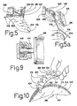
- a lever 120 To each end of the pivot shaft of the deflector plate 116 is secured a lever 120 (see Figures 5 and 5a) to which is attached a toggle spring 122, the other end of the tension spring being attached to an end wall 34.
- the two tension springs 122 resiliently maintains the deflector plate 116 in open or closed position.
- aperture 114 allows direct ejection of the material through the duct 100 and then through opening 102 to the outside of the casing.
- the closed position of the deflector plate 116 as shown in Figure 5a, there is formed a continuous passage between the rotor and the partitions 110 and 112 and deflector plate 116, which starts at the shoe 88 and extends around the rotor to open at the front edge of the closed cover, so that the material may be discharged ahead of the apparatus and recuperated in a bag installed in front of the mower.
- a roller 124 extends transversely of the casing behind the rotor and below the same, being journalled at its two ends to levers 126.
- Each lever 126 is pivoted intermediate its ends at 128 to an end wall 32 just inside the same, and the rear end of lever 126 is attached by means of a flexible link, such as a bicycle chain 130, to the lower end of a plunger 134, which is guided for up-and-down movement in a sleeve 136 fixed in upright position in the casing, and more particularly through a transverse reinforcing tube 138 fixed to the end walls.
- Plunger 134 is rotatably attached to a screw 140, which is screwed within a nut 142 fixed to the top end of the sleeve 136. Rotation of the screw 140, by means for instance of handle 144, will adjust the level of the plunger 134 and, consequently, the level of the roller 124 with respect to the rotor 36.
- the two handles 144 are rotated to the same extent, so as to ensure that the casing be transversely levelled with respect to the ground.
- the two hubs 148 of the handles 144 could be arranged as sprockets with an endless chain trained on said sprockets, so that rotation of one or the other of the handles 144 will displace the two plungers 134 to the same extent up or down.
- a tension spring 150 is connected to each lever 126 intermediate the roller 124 and the pivot 128 and is also connected at its top end to the reinforcing tube 138.
- Figure 3 shows an arrangement where both ends of the rotor are driven by a hydraulic motor 50, the latter being mounted on the outside of the casing.
- Figures 11, 12, and 13 show alternate arrangements in which the rotor is driven from only end and in which the driving hydraulic motor may be mounted directly within the rotor.
- the hydraulic motor 50A is fixed by bolts 52 to an end wall 32 inside the casing and extends within the rotor, one end cap of which being modified, as shown at 40A, to provide a sufficient opening for insertion of the motor 50A, the end cap rotatably journalled on the rotor by a large diameter ball bearing arrangement 154.
- the output shaft 156 of the motor 58A is removably splined into an end of a shaft 158, which has a collar 160 removably bolted to the other end cap 40B.
- the shaft 158 is journalled in a bearing 162 carried by a plug 164 secured within a hole made in the other end wall 32 of the casing by bolts 166.
- Figure 13 shows an alternate arrangement wherein one end cap 40C forms a deep recess 170, in which the internally-mounted hydraulic motor 50A is freely inserted, the output shaft of said motor being directly keyed in a hole in the bottom of recess 170.
- This figure also shows that the end caps are provided with an inwardly-facing step 172 at their periphery, overlapping the end of the cylindrical wall 38 of the rotor to prevent disengagement under centrifugal force, if found necessary.
- Figure 12 shows another embodiment in which the rotor is driven from one end with the driving motor or gear at the outside of the casing 26.
- the arrangement is very similar to that of Figure 13 as far as the right-hand side of the rotor is concerned; but the end cap on the left-hand side is modified so as to secure the drive shaft 174 to the end cap by bolts 176.
- the rasp teeth normally simply ride over rocks or pebbles lying in the grass and will not become damaged by the same.
- the rasp 62 may be modified, as shown at 62A, with the steel of each tooth 78 being only partially punched out and remaining attached to the tooth at the otherwise cutting edge to form a part 178, 179 which is then bent at right angles to the rasp successively in opposite directions, so as to act as a snow impeller.
- the top outward edge of the bent part 178, 179 will not extend to the tip 80 of the tooth, so that the latter will be able to engage and cut ice, which will be comminuted, and the ice and snow thrown out of the casing by the impellers 178, 179.
- Impellers 178, 179 may extend on only one side of the blade and ⁇ or be formed at only every third tooth, if so desired.
- rasps 62 can be easily removed and replaced, it is a simple matter to have rasps of different kinds, that is with different types of teeth, even carbide teeth, to adapt the rotor to various kinds of works, such as wood chipping, and chipping of other types of materials including plastic.
- the rotor can be mounted, as shown in Figure 14, with material M to be chipped located on a table 182 transversely disposed along a radius of the rotor and having a front edge 184 disposed parallel to the rotational axis of the rotor and close to the tip 80 of the teeth. Material M is pushed over the teeth to be comminuted by means of a pusher 186.
- the rotor assembly including the rasps 62, can be put to different uses for cutting or comminuting different types of material.
Applications Claiming Priority (2)
| Application Number | Priority Date | Filing Date | Title |
|---|---|---|---|
| US07/214,372 US4887418A (en) | 1988-07-05 | 1988-07-05 | Apparatus for mowing, chipping and blowing |
| US214372 | 1994-03-17 |
Publications (3)
| Publication Number | Publication Date |
|---|---|
| EP0349944A2 true EP0349944A2 (fr) | 1990-01-10 |
| EP0349944A3 EP0349944A3 (fr) | 1993-06-16 |
| EP0349944B1 EP0349944B1 (fr) | 1995-12-27 |
Family
ID=22798838
Family Applications (1)
| Application Number | Title | Priority Date | Filing Date |
|---|---|---|---|
| EP89112067A Expired - Lifetime EP0349944B1 (fr) | 1988-07-05 | 1989-07-01 | Appareil à faucher, couper et souffler |
Country Status (5)
| Country | Link |
|---|---|
| US (1) | US4887418A (fr) |
| EP (1) | EP0349944B1 (fr) |
| JP (1) | JPH02126944A (fr) |
| AU (1) | AU620418B2 (fr) |
| DE (1) | DE68925242D1 (fr) |
Cited By (2)
| Publication number | Priority date | Publication date | Assignee | Title |
|---|---|---|---|---|
| WO1991013539A1 (fr) * | 1990-03-05 | 1991-09-19 | Hanafi Ameur | Machine polyvalente |
| WO2003077637A2 (fr) * | 2002-03-20 | 2003-09-25 | Mats Fischier i Båstad AB | Tondeuse a gazon a cylindre et unite cylindre destinee a cette derniere |
Families Citing this family (10)
| Publication number | Priority date | Publication date | Assignee | Title |
|---|---|---|---|---|
| US4999984A (en) * | 1988-07-05 | 1991-03-19 | Guy Pelletier | Cutting blades for use in mowers and chippers |
| US4947630A (en) * | 1989-10-03 | 1990-08-14 | Rich Frank C | Golf greens mower with self-cleaning ground contacting rollers |
| JP2855089B2 (ja) * | 1995-06-07 | 1999-02-10 | 政則 西岡 | 引きずり式草刈り機 |
| US6430902B1 (en) | 1997-12-09 | 2002-08-13 | Textron, Inc. | Mower cutting unit having an internal motor |
| US6250056B1 (en) * | 1998-01-05 | 2001-06-26 | F & T Spagnolo Pty Ltd. | Rotary blade pruning machine |
| US6178729B1 (en) * | 1999-04-09 | 2001-01-30 | Laszlo Vastag | Lawn mower with a deck formed with a trap door |
| US6862874B2 (en) | 2002-04-22 | 2005-03-08 | Deere & Company | Discharge stopper units for mower decks |
| DE10234814A1 (de) * | 2002-07-31 | 2004-02-19 | Walter Kolb | Schneidvorrichtung für Pflanzen |
| JP6340921B2 (ja) * | 2014-05-30 | 2018-06-13 | 日立工機株式会社 | 芝刈機 |
| DE102020120329A1 (de) * | 2020-07-31 | 2022-02-03 | Ilmer Maschinenbau GmbH | Trimmvorrichtung |
Citations (11)
| Publication number | Priority date | Publication date | Assignee | Title |
|---|---|---|---|---|
| US2282238A (en) * | 1940-10-31 | 1942-05-05 | Richard T Newton | Lawn mower for grass, grains, and the like |
| US2584262A (en) * | 1949-11-15 | 1952-02-05 | Sr Boyd E De Lamater | Rotary cutter |
| US2644501A (en) * | 1951-05-15 | 1953-07-07 | Price W Perry | Cutting element for composting machines or hay comminuting machines |
| US3029583A (en) * | 1959-09-08 | 1962-04-17 | Patt Sylvester | Cutter bar and reel |
| GB1100220A (en) * | 1966-01-05 | 1968-01-24 | Catharinus Sinke | Mowing machine |
| NL6707168A (fr) * | 1967-05-24 | 1968-11-25 | ||
| DE2044812A1 (de) * | 1969-09-26 | 1971-04-08 | N V Philips Gloeilampenfabrieken, Eindhoven (Niederlande) | Kafigmaher mit einem selbsterregend angeordneten Käfig |
| US4127980A (en) * | 1976-11-11 | 1978-12-05 | Ferguson Hugo S | Crossflow mower with automatic brake/sharpener |
| WO1984002252A1 (fr) * | 1982-12-17 | 1984-06-21 | Taarup As Maskinfab | Tambour d'acheminement permettant de faire avancer de la paille dans un vehicule a auto-chargement |
| AU548518B3 (en) * | 1985-10-28 | 1985-11-28 | Chamberlain John Deere Pty. Ltd. | Improvements in harvesting cutting platforms |
| EP0271672A2 (fr) * | 1986-10-22 | 1988-06-22 | Franz Prof. Dr.-Ing. Wieneke | Faucheuse hélicoidale |
Family Cites Families (18)
| Publication number | Priority date | Publication date | Assignee | Title |
|---|---|---|---|---|
| US2000249A (en) * | 1934-08-08 | 1935-05-07 | Victor G Pew | Lawn mower attachment |
| US2566724A (en) * | 1947-04-30 | 1951-09-04 | John P Heil | Combination lawn mowel and snowplow |
| US2865572A (en) * | 1954-03-29 | 1958-12-23 | Chicago Pump Co | Comminuting cylinder with individual mounted cutting and shearing teeth |
| US2831308A (en) * | 1954-09-27 | 1958-04-22 | Andrew L Raba | Grass cutter |
| US2923117A (en) * | 1957-05-20 | 1960-02-02 | Scott W Henderson | Rotary cutter |
| US3073100A (en) * | 1960-08-15 | 1963-01-15 | Richard O Kingsley | Mower having helical cutter blade |
| GB1001264A (en) * | 1961-04-12 | 1965-08-11 | Ransomes Sims & Jefferies Ltd | Improvements in or relating to mowing machines |
| US3099124A (en) * | 1961-04-17 | 1963-07-30 | Jacobsen Mfg Co | Lawn mower roller adjustment |
| US3271939A (en) * | 1963-12-19 | 1966-09-13 | Union Carbide Corp | Powered unit for a lawn mower or similar device |
| US3292353A (en) * | 1964-09-28 | 1966-12-20 | Int Harvester Co | Flail mower structure |
| US3690047A (en) * | 1971-09-21 | 1972-09-12 | Roy M Thoen | Combination lawn mowing and snow throwing machine |
| US3797214A (en) * | 1972-11-10 | 1974-03-19 | Deere & Co | Mower discharge chute deflector and bagging attachment |
| US4008559A (en) * | 1974-02-26 | 1977-02-22 | The Black And Decker Manufacturing Company | Safety deflector assembly for power lawn discharge chute |
| US3935695A (en) * | 1974-05-02 | 1976-02-03 | Merry Richard C | Non-marking lawn mower |
| US4028868A (en) * | 1976-02-23 | 1977-06-14 | Bluebird International, Inc. | Towable lawn comber |
| AU2343784A (en) * | 1982-12-17 | 1984-07-05 | Maskinfabriken Taarup A/S | A conveyor drum for advancing straw material in a self- loading vehicle |
| US4550554A (en) * | 1984-01-03 | 1985-11-05 | Ezra C. Lundahl, Inc. | Crop processor |
| US4572258A (en) * | 1985-01-24 | 1986-02-25 | Mischel Kenneth J | Chain flail |
-
1988
- 1988-07-05 US US07/214,372 patent/US4887418A/en not_active Expired - Lifetime
-
1989
- 1989-07-01 EP EP89112067A patent/EP0349944B1/fr not_active Expired - Lifetime
- 1989-07-01 DE DE68925242T patent/DE68925242D1/de not_active Expired - Lifetime
- 1989-07-04 AU AU37831/89A patent/AU620418B2/en not_active Ceased
- 1989-07-05 JP JP1172091A patent/JPH02126944A/ja active Pending
Patent Citations (11)
| Publication number | Priority date | Publication date | Assignee | Title |
|---|---|---|---|---|
| US2282238A (en) * | 1940-10-31 | 1942-05-05 | Richard T Newton | Lawn mower for grass, grains, and the like |
| US2584262A (en) * | 1949-11-15 | 1952-02-05 | Sr Boyd E De Lamater | Rotary cutter |
| US2644501A (en) * | 1951-05-15 | 1953-07-07 | Price W Perry | Cutting element for composting machines or hay comminuting machines |
| US3029583A (en) * | 1959-09-08 | 1962-04-17 | Patt Sylvester | Cutter bar and reel |
| GB1100220A (en) * | 1966-01-05 | 1968-01-24 | Catharinus Sinke | Mowing machine |
| NL6707168A (fr) * | 1967-05-24 | 1968-11-25 | ||
| DE2044812A1 (de) * | 1969-09-26 | 1971-04-08 | N V Philips Gloeilampenfabrieken, Eindhoven (Niederlande) | Kafigmaher mit einem selbsterregend angeordneten Käfig |
| US4127980A (en) * | 1976-11-11 | 1978-12-05 | Ferguson Hugo S | Crossflow mower with automatic brake/sharpener |
| WO1984002252A1 (fr) * | 1982-12-17 | 1984-06-21 | Taarup As Maskinfab | Tambour d'acheminement permettant de faire avancer de la paille dans un vehicule a auto-chargement |
| AU548518B3 (en) * | 1985-10-28 | 1985-11-28 | Chamberlain John Deere Pty. Ltd. | Improvements in harvesting cutting platforms |
| EP0271672A2 (fr) * | 1986-10-22 | 1988-06-22 | Franz Prof. Dr.-Ing. Wieneke | Faucheuse hélicoidale |
Cited By (5)
| Publication number | Priority date | Publication date | Assignee | Title |
|---|---|---|---|---|
| WO1991013539A1 (fr) * | 1990-03-05 | 1991-09-19 | Hanafi Ameur | Machine polyvalente |
| WO2003077637A2 (fr) * | 2002-03-20 | 2003-09-25 | Mats Fischier i Båstad AB | Tondeuse a gazon a cylindre et unite cylindre destinee a cette derniere |
| WO2003077637A3 (fr) * | 2002-03-20 | 2003-11-27 | Mats Fischier I Baastad Ab | Tondeuse a gazon a cylindre et unite cylindre destinee a cette derniere |
| EP1769665A1 (fr) * | 2002-03-20 | 2007-04-04 | Mats Fischier I Bastad AB | Tondeuse à gazon à cylindre et unité cylindrique destinée à cette dernière |
| US7213390B2 (en) | 2002-03-20 | 2007-05-08 | Mats Fischier i Båstad AB | Cylinder lawn mower and cylinder unit intended therefor |
Also Published As
| Publication number | Publication date |
|---|---|
| JPH02126944A (ja) | 1990-05-15 |
| DE68925242D1 (de) | 1996-02-08 |
| AU620418B2 (en) | 1992-02-20 |
| EP0349944B1 (fr) | 1995-12-27 |
| EP0349944A3 (fr) | 1993-06-16 |
| AU3783189A (en) | 1990-01-11 |
| US4887418A (en) | 1989-12-19 |
Similar Documents
| Publication | Publication Date | Title |
|---|---|---|
| US4951449A (en) | Convertible lawn mower | |
| EP0349944B1 (fr) | Appareil à faucher, couper et souffler | |
| US5435118A (en) | Vacuum sweeper shredder rotary mower | |
| US4875630A (en) | Leaf vacuum and shredder | |
| US5090183A (en) | Discharge chute blocking device for a rotary lawn mower | |
| US4326370A (en) | Rotary lawn mower | |
| US6192666B1 (en) | Lawn mower | |
| US5987863A (en) | Lawn mower having flow control baffles and removable mulching baffles | |
| US2735199A (en) | Rotary snow plow | |
| US5020309A (en) | Leaf shredder attachment for a mower bagging system | |
| US5390865A (en) | Processor for chipping and shredding vegetatation | |
| DE3934636A1 (de) | Rasenmaeher mit geblaese | |
| US5102056A (en) | Combination leaf and lawn debris comminuting vacuum and wood chipper | |
| US4905460A (en) | Mulching bar for a core processor or power rake | |
| EP1527668B1 (fr) | Chassis de tondeuse et tondeuse | |
| US3673773A (en) | Cross-flow mowing machine | |
| US6062013A (en) | Mulching mower with uniform cut and particulate distribution | |
| US4999984A (en) | Cutting blades for use in mowers and chippers | |
| US3690047A (en) | Combination lawn mowing and snow throwing machine | |
| US6003292A (en) | Brush mower with deflection plate | |
| US3367091A (en) | Lawn care unit | |
| DE2624983A1 (de) | Rasenmaeher | |
| CA1286117C (fr) | Dispositif pour tondre, dechiqueter et souffler | |
| DE4034978C2 (fr) | ||
| WO2013188863A1 (fr) | Système de traitement et de ramassage de déchets au balai |
Legal Events
| Date | Code | Title | Description |
|---|---|---|---|
| PUAI | Public reference made under article 153(3) epc to a published international application that has entered the european phase |
Free format text: ORIGINAL CODE: 0009012 |
|
| AK | Designated contracting states |
Kind code of ref document: A2 Designated state(s): DE FR GB IT NL SE |
|
| PUAL | Search report despatched |
Free format text: ORIGINAL CODE: 0009013 |
|
| AK | Designated contracting states |
Kind code of ref document: A3 Designated state(s): DE FR GB IT NL SE |
|
| 17P | Request for examination filed |
Effective date: 19931202 |
|
| 17Q | First examination report despatched |
Effective date: 19950307 |
|
| GRAA | (expected) grant |
Free format text: ORIGINAL CODE: 0009210 |
|
| AK | Designated contracting states |
Kind code of ref document: B1 Designated state(s): DE FR GB IT NL SE |
|
| PG25 | Lapsed in a contracting state [announced via postgrant information from national office to epo] |
Ref country code: IT Free format text: LAPSE BECAUSE OF FAILURE TO SUBMIT A TRANSLATION OF THE DESCRIPTION OR TO PAY THE FEE WITHIN THE PRESCRIBED TIME-LIMIT;WARNING: LAPSES OF ITALIAN PATENTS WITH EFFECTIVE DATE BEFORE 2007 MAY HAVE OCCURRED AT ANY TIME BEFORE 2007. THE CORRECT EFFECTIVE DATE MAY BE DIFFERENT FROM THE ONE RECORDED. Effective date: 19951227 Ref country code: NL Free format text: LAPSE BECAUSE OF FAILURE TO SUBMIT A TRANSLATION OF THE DESCRIPTION OR TO PAY THE FEE WITHIN THE PRESCRIBED TIME-LIMIT Effective date: 19951227 |
|
| REF | Corresponds to: |
Ref document number: 68925242 Country of ref document: DE Date of ref document: 19960208 |
|
| ET | Fr: translation filed | ||
| PG25 | Lapsed in a contracting state [announced via postgrant information from national office to epo] |
Ref country code: SE Effective date: 19960327 |
|
| PG25 | Lapsed in a contracting state [announced via postgrant information from national office to epo] |
Ref country code: DE Effective date: 19960328 |
|
| NLV1 | Nl: lapsed or annulled due to failure to fulfill the requirements of art. 29p and 29m of the patents act | ||
| PLBE | No opposition filed within time limit |
Free format text: ORIGINAL CODE: 0009261 |
|
| STAA | Information on the status of an ep patent application or granted ep patent |
Free format text: STATUS: NO OPPOSITION FILED WITHIN TIME LIMIT |
|
| 26N | No opposition filed | ||
| PGFP | Annual fee paid to national office [announced via postgrant information from national office to epo] |
Ref country code: GB Payment date: 19990630 Year of fee payment: 11 |
|
| PGFP | Annual fee paid to national office [announced via postgrant information from national office to epo] |
Ref country code: FR Payment date: 19990721 Year of fee payment: 11 |
|
| PG25 | Lapsed in a contracting state [announced via postgrant information from national office to epo] |
Ref country code: GB Free format text: LAPSE BECAUSE OF NON-PAYMENT OF DUE FEES Effective date: 20000701 |
|
| GBPC | Gb: european patent ceased through non-payment of renewal fee |
Effective date: 20000701 |
|
| PG25 | Lapsed in a contracting state [announced via postgrant information from national office to epo] |
Ref country code: FR Free format text: LAPSE BECAUSE OF NON-PAYMENT OF DUE FEES Effective date: 20010330 |
|
| REG | Reference to a national code |
Ref country code: FR Ref legal event code: ST |