EP0349933A2 - Boîtier pour composants sensibles à l'infrarouge - Google Patents
Boîtier pour composants sensibles à l'infrarouge Download PDFInfo
- Publication number
- EP0349933A2 EP0349933A2 EP89112031A EP89112031A EP0349933A2 EP 0349933 A2 EP0349933 A2 EP 0349933A2 EP 89112031 A EP89112031 A EP 89112031A EP 89112031 A EP89112031 A EP 89112031A EP 0349933 A2 EP0349933 A2 EP 0349933A2
- Authority
- EP
- European Patent Office
- Prior art keywords
- housing
- housing according
- heat exchanger
- exchanger tube
- joule
- Prior art date
- Legal status (The legal status is an assumption and is not a legal conclusion. Google has not performed a legal analysis and makes no representation as to the accuracy of the status listed.)
- Granted
Links
Images
Classifications
-
- F—MECHANICAL ENGINEERING; LIGHTING; HEATING; WEAPONS; BLASTING
- F25—REFRIGERATION OR COOLING; COMBINED HEATING AND REFRIGERATION SYSTEMS; HEAT PUMP SYSTEMS; MANUFACTURE OR STORAGE OF ICE; LIQUEFACTION SOLIDIFICATION OF GASES
- F25D—REFRIGERATORS; COLD ROOMS; ICE-BOXES; COOLING OR FREEZING APPARATUS NOT OTHERWISE PROVIDED FOR
- F25D19/00—Arrangement or mounting of refrigeration units with respect to devices or objects to be refrigerated, e.g. infrared detectors
- F25D19/006—Thermal coupling structure or interface
-
- F—MECHANICAL ENGINEERING; LIGHTING; HEATING; WEAPONS; BLASTING
- F25—REFRIGERATION OR COOLING; COMBINED HEATING AND REFRIGERATION SYSTEMS; HEAT PUMP SYSTEMS; MANUFACTURE OR STORAGE OF ICE; LIQUEFACTION SOLIDIFICATION OF GASES
- F25B—REFRIGERATION MACHINES, PLANTS OR SYSTEMS; COMBINED HEATING AND REFRIGERATION SYSTEMS; HEAT PUMP SYSTEMS
- F25B9/00—Compression machines, plants or systems, in which the refrigerant is air or other gas of low boiling point
- F25B9/02—Compression machines, plants or systems, in which the refrigerant is air or other gas of low boiling point using Joule-Thompson effect; using vortex effect
-
- H—ELECTRICITY
- H10—SEMICONDUCTOR DEVICES; ELECTRIC SOLID-STATE DEVICES NOT OTHERWISE PROVIDED FOR
- H10F—INORGANIC SEMICONDUCTOR DEVICES SENSITIVE TO INFRARED RADIATION, LIGHT, ELECTROMAGNETIC RADIATION OF SHORTER WAVELENGTH OR CORPUSCULAR RADIATION
- H10F77/00—Constructional details of devices covered by this subclass
- H10F77/60—Arrangements for cooling, heating, ventilating or compensating for temperature fluctuations
Definitions
- the invention relates to a housing for optoelectronic components according to the preamble of claim 1.
- Joule-Thomson coolers are generally used, in which the temperature of the gas is reduced by adiabatic expansion of a gas compressed to 100-300 bar.
- the highly compressed gas flowing in from a high-pressure gas storage device or a compressor is pre-cooled in a heat exchanger tube of the Joule-Thomson cooler, which separates two media with different temperatures, before it is expanded by the back-flowing expanded gas.
- the process steps of lowering the temperature by means of adiabatic expansion and pre-cooling Liquefaction of the compressed gas in the heat exchanger can liquefy the cooling medium, for example nitrogen or argon gas.
- the operating temperature of the component then corresponds to the liquefaction temperature of the cooling medium used.
- Joule-Thomson coolers For cooling optoelectronic components with Joule-Thomson coolers, embodiments are known in which the entire Joule-Thomson cooler is conventionally inserted tightly into a completely separable housing which consists of a glass inner wall and a metallic outer wall for thermal insulation.
- the heat exchanger tube of the Joule-Thomson cooler is spirally wound onto a cylindrical or conical metallic carrier body and then soldered on.
- metallic ribs can be soldered to the outside of the heat exchanger tube, which increase the effective surface area of the heat exchanger.
- the component to be cooled is located in the fully separable housing near the front of the Joule-Thomson cooler at the level of the expansion nozzle, since the temperature is lowest there and the cooling effect is therefore most effective.
- the Dewar housing surrounding the Joule-Thomson cooler is evacuated so that the top of the component is not iced up by gas condensation and the component becomes unusable as a result.
- the disadvantage here is that stability problems arise due to the low strength of the thin-walled metallic carrier body.
- a high manufacturing effort is required, since the support body is galvanically deposited as a molded part, the heat exchanger tube is first wound onto the support body and then soldered, and the Joule-Thomson cooler must also be inserted into a very precisely adapted housing for insulation purposes.
- the invention is therefore based on the object of developing a housing in which the requirement for poor thermal conductivity of the carrier body and the associated good and rapid cooling effect of the Joule-Thomson cooler is combined with a high mechanical stability of the housing and a reduction in production costs .
- the lower housing part and the central housing part which include a heat exchanger tube of the Joule-Thomson cooler, consist of a material with low thermal conductivity and that the heat exchanger tube is arranged spirally in one plane.
- housing middle part and housing lower part which enclose the heat exchanger tube
- these parts can be thick be walled.
- the heat conduction in the radial direction is preferably additionally reduced by ribbing the housing parts mentioned. Due to the flat planar arrangement of the heat exchanger tube and the fact that the housing and the Joule-Thomson cooler form a unit and the individual parts of the housing are firmly connected, preferably screwed, stability against high pressures and external influences such as shock, vibrations and Temperature fluctuations also increased.
- the middle part of the housing and the lower part of the housing preferably consist of plastic materials with poor thermal conductivity, for example polyimide or polyphenylene sulfide. Because of their simple design, these plastic housing parts can be mass-produced as injection molded parts, which considerably simplifies production.
- the operating temperature of the component to be cooled is reached in less than 1 s. Because of the poor thermal conductivity of the middle part of the housing and the lower part of the housing and the high thermal conductivity and heat capacity of the upper part of the housing with a window, no vacuum is required for short-term operation. With longer operating times, e.g. longer than 5 min. , the element space surrounding the optoelectronic component can be evacuated.
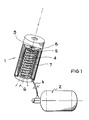
- FIG. 1 A Joule-Thomson cooler 1 with an open circuit is described in FIG. 1, in which the compressed cooling medium flows from a high-pressure gas store 2 into the heat exchanger tube 3, which is spirally wound around a metallic carrier body 4. After passing through the heat exchanger tube 3, the warm gas expands adiabatically in an expansion nozzle 5, which leads to a cooling of the working gas depending on the type of gas and pressure.
- the cold gas 6 runs downward on the outside of the heat exchanger tube 3 and thus cools the inflowing compressed warm gas before it emerges from the cooler 1 into the environment.
- An insulating vacuum or insulating shield 7 is used for thermal insulation from the environment.
- the object to be cooled is often designed as a cooling finger 8, which cools, for example, a detector 9 near the end of the Joule-Thomson cooler.
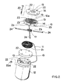
- the housing for the optoelectronic component consists of the following three parts screwed together:
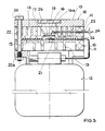
- the lower part 10 of the housing is preferably made of plastic and serves as a boundary wall for the heat exchanger tube 11 and for the back-flowing expanded gas. Because of the low thermal conductivity of the plastic material used, for example polyimide, there is excellent thermal insulation with respect to the surroundings and the metallic gas storage container 12, which can be designed as a carrier body for the housing. 3, ribs 13 in the form of concentric circles are additionally attached to the underside of the plastic part 10 in order to increase the insulation effect.
- the middle housing part 14 is made of the same material as the lower housing part 10 and contains on its underside webs 15 in which the heat exchanger tube 11 is guided and held.
- the top of the middle housing part 14 is ribbed, as is the underside of the lower housing part 10.
- the element carrier 17 is applied in a round recess 16 in the middle of this housing part.
- the upper housing part 18 consists of a thin metal plate; the entrance window 19 for the radiation to be detected is integrated into this. Because of the good thermal conductivity and the thermal mass of the metal, premature fogging of the entrance window 19 is avoided.
- the entrance window 19 must be transparent to the radiation to be detected; For example, a Ge entry window is used in the infrared spectral range.
- the housing parts 10, 14, 18 mentioned can additionally be fastened to the gas storage container 12, for example by means of screws 20 and nuts 20a.
- screw openings 22 are provided in the three housing parts and in the gas storage container.
- the Joule-Thomson cooler according to FIGS. 2 and 3 has an open circuit, depending on the size of the gas storage container 12, an operating time of 30-60 s is possible.
- the heat exchanger tube 11 consists of a stainless steel tube which is approved for pressures up to 1000 bar.
- metallic fins not shown in FIGS. 2 and 3 are soldered to the heat exchanger tube 11, which are made of a metal with good heat conduction and low heat capacity, preferably molybdenum.
- the compressed gas is expanded on a capillary 21 at the end of the heat exchanger tube 11 and, after the incoming gas has been pre-cooled, flows radially outwards through recesses 26 in the middle part 14 of the housing.
- the element space 16a which contains the element carrier 17 and the semiconductor component 23 mounted on this carrier, is upwards through the metallic housing upper part 18, sideways through the housing middle part 14 made of plastic and downwards through the metallic element carrier 17 hermetically sealed.
- the element space 16a can also be evacuated, which for short operating times because of the low condensable gas volume However, mens is not required.
- the optoelectronic semiconductor component 23 is usually a ternary semiconductor, preferably based on HgCdTe.
- the element carrier 17 consists of a material with good thermal conductivity, for example molybdenum or silicon, and is either glued into the recess 16 in the middle part of the housing or soldered in after the plastic has been metallized on the contact surfaces. On its underside, the element carrier 17 is cooled by the cold gas.
- the conductor track leads 24 for contacting the component are passed radially outward through the plastic and glued into bores 25 of the middle housing part 14 or soldered into the previously metallized contact areas in the plastic.
- the element space 16a can be evacuated, as a result of which fogging of the entry window 19 by heat conduction via the gas filling of the element space is avoided.
- the entire 3-part housing made of upper, middle and lower part is 15 mm high and has a diameter of 35 mm; the plastic lower part has 4 ribs, the plastic middle part 5 ribs in the form of concentric circles.
- the heat exchanger tube made of stainless steel describes 10 turns, 4 webs are attached in the middle part of the housing to guide this tube.
- the inside of the heat exchanger tube has a diameter of 0.35 mm and the outside of 0.55 mm; on the outside, ribs made of molybdenum are soldered, which are approx. 2 mm high and have a lateral distance of approx. 0.2 mm.
- the compressed gas relaxes in a capillary at the end of the innermost turn of the tube; this capillary is designed as a 0.1 mm bore on the side of the tube.
- the detector element an HgCdTe semiconductor, sits on an element carrier made of silicon in a recess in the middle of the middle part of the housing, which has a diameter of 6 mm.
- the element carrier has an area of approx. 30 mm2, the detector element has an area of approx. 5 mm2.
- the gas supply has a volume of 20 cm3, for example, and is contained in a high-pressure container made of stainless steel, which is firmly connected to the housing with 4 screws.
- the operating temperature of the detector element is reached in less than 1 s and an operating time of approximately 20 s is made possible.
- the housings described with integrated Joule-Thomson coolers can be used in a variety of ways. In particular are possible applications that involve extremely high environmental pollution, such as shock, vibration, etc.
- the optoelectronic components to be cooled can be both individual elements and multi-element detector arrays.
- the signal processing by preamplifier or multiplexer can be done externally or within the integrated housing-cooler arrangement.
Landscapes
- Engineering & Computer Science (AREA)
- Physics & Mathematics (AREA)
- Mechanical Engineering (AREA)
- Thermal Sciences (AREA)
- General Engineering & Computer Science (AREA)
- Chemical & Material Sciences (AREA)
- Combustion & Propulsion (AREA)
- Cooling Or The Like Of Semiconductors Or Solid State Devices (AREA)
- Radiation Pyrometers (AREA)
Applications Claiming Priority (2)
| Application Number | Priority Date | Filing Date | Title |
|---|---|---|---|
| DE3823006A DE3823006C2 (de) | 1988-07-07 | 1988-07-07 | Gehäuse für infrarotempfindliche Bauelemente |
| DE3823006 | 1988-07-07 |
Publications (3)
| Publication Number | Publication Date |
|---|---|
| EP0349933A2 true EP0349933A2 (fr) | 1990-01-10 |
| EP0349933A3 EP0349933A3 (en) | 1990-11-22 |
| EP0349933B1 EP0349933B1 (fr) | 1995-09-06 |
Family
ID=6358157
Family Applications (1)
| Application Number | Title | Priority Date | Filing Date |
|---|---|---|---|
| EP89112031A Expired - Lifetime EP0349933B1 (fr) | 1988-07-07 | 1989-07-01 | Boîtier pour composants sensibles à l'infrarouge |
Country Status (3)
| Country | Link |
|---|---|
| US (1) | US4974062A (fr) |
| EP (1) | EP0349933B1 (fr) |
| DE (2) | DE3823006C2 (fr) |
Cited By (2)
| Publication number | Priority date | Publication date | Assignee | Title |
|---|---|---|---|---|
| FR2725013A1 (fr) * | 1994-09-22 | 1996-03-29 | Air Liquide | Refroidisseur joule-thomson |
| FR2782785A1 (fr) | 1998-08-27 | 2000-03-03 | Air Liquide | Refroidisseur joule-thomson |
Families Citing this family (2)
| Publication number | Priority date | Publication date | Assignee | Title |
|---|---|---|---|---|
| FR2834127B1 (fr) * | 2001-12-26 | 2005-01-14 | Sagem | Photodetecteur refroidi |
| DE10216786C5 (de) * | 2002-04-15 | 2009-10-15 | Ers Electronic Gmbh | Verfahren und Vorrichtung zur Konditionierung von Halbleiterwafern und/oder Hybriden |
Family Cites Families (10)
| Publication number | Priority date | Publication date | Assignee | Title |
|---|---|---|---|---|
| US2951944A (en) * | 1958-03-10 | 1960-09-06 | Itt | Radiation sensitive device |
| GB1168997A (en) * | 1965-12-08 | 1969-10-29 | Emi Ltd | Improvements relating to Cooling Apparatus |
| GB1401434A (en) * | 1971-09-30 | 1975-07-16 | Mullard Ltd | Photo-electric devices |
| CH654694A5 (de) * | 1981-09-01 | 1986-02-28 | Bbc Brown Boveri & Cie | Verfahren zur kuehlung von halbleiterelementen und kuehler zur durchfuehrung des verfahrens. |
| GB2119071B (en) * | 1982-04-19 | 1985-07-03 | British Aerospace | Joule-thomson cooling apparatus |
| US4488414A (en) * | 1983-10-03 | 1984-12-18 | Honeywell Inc. | Disc detector assembly |
| DE3337195A1 (de) * | 1983-10-13 | 1985-04-25 | Telefunken electronic GmbH, 7100 Heilbronn | Anordnung fuer ein bei niederen temperaturen betriebsfaehiges elektronisches bauelement |
| DE3337194A1 (de) * | 1983-10-13 | 1985-04-25 | Telefunken electronic GmbH, 7100 Heilbronn | Gehaeuse fuer ein optoelektronisches halbleiterbauelement |
| GB2186740B (en) * | 1986-02-14 | 1989-11-08 | Philips Electronic Associated | Infrared detectors |
| FR2602316B1 (fr) * | 1986-07-31 | 1988-08-26 | Air Liquide | Refroidisseur joule-thomson, procede de fabrication et cryostat comprenant ce refroidisseur |
-
1988
- 1988-07-07 DE DE3823006A patent/DE3823006C2/de not_active Expired - Fee Related
-
1989
- 1989-05-24 US US07/356,239 patent/US4974062A/en not_active Expired - Lifetime
- 1989-07-01 DE DE58909418T patent/DE58909418D1/de not_active Expired - Fee Related
- 1989-07-01 EP EP89112031A patent/EP0349933B1/fr not_active Expired - Lifetime
Cited By (3)
| Publication number | Priority date | Publication date | Assignee | Title |
|---|---|---|---|---|
| FR2725013A1 (fr) * | 1994-09-22 | 1996-03-29 | Air Liquide | Refroidisseur joule-thomson |
| FR2782785A1 (fr) | 1998-08-27 | 2000-03-03 | Air Liquide | Refroidisseur joule-thomson |
| US6202422B1 (en) | 1998-08-27 | 2001-03-20 | L'air Liquide, Societe Anonyme Pour L'etude Et L'exploitation Des Procedes Georges Claude | Joule-Thomson cooler |
Also Published As
| Publication number | Publication date |
|---|---|
| US4974062A (en) | 1990-11-27 |
| EP0349933B1 (fr) | 1995-09-06 |
| DE58909418D1 (de) | 1995-10-12 |
| DE3823006A1 (de) | 1990-01-11 |
| EP0349933A3 (en) | 1990-11-22 |
| DE3823006C2 (de) | 1994-09-08 |
Similar Documents
| Publication | Publication Date | Title |
|---|---|---|
| DE3337194C2 (fr) | ||
| DE2647758C3 (de) | Kühlungsmodul für elektrische Bauteile | |
| DE69103055T2 (de) | Zweistufiger Joule-Thomson-Kryostat mit Gaszufuhrsteuerungssystem und dessen Verwendungen. | |
| DE3337195C2 (fr) | ||
| DE3642683C2 (fr) | ||
| DE102015215919B4 (de) | Verfahren und Vorrichtung zur Vorkühlung eines Kryostaten | |
| EP2068103A2 (fr) | Module de mesure destiné à la mesure rapide de composants électriques, électroniques et mécaniques à des températures cryogènes et dispositif de mesure doté d'un tel module de mesure | |
| DE3786469T2 (de) | Infrarotdetektor. | |
| EP0349933B1 (fr) | Boîtier pour composants sensibles à l'infrarouge | |
| DE4129547C2 (de) | Cryostat | |
| DE1501106A1 (de) | Gasexpansionskuehlvorrichtung | |
| EP0373445A2 (fr) | Refroidisseur Joule-Thomson | |
| DE3605554A1 (de) | Verschiessbarer kuehlkoerper | |
| DE60010297T2 (de) | Abgedichtete kältemitteleinheit für ein kühlgerät | |
| DE102004042398B4 (de) | Kühlvorrichtung | |
| DE2803438A1 (de) | Kuehlvorrichtung | |
| DE202016106860U1 (de) | Regenerator für Kryo-Kühler mit Helium als Arbeitsgas | |
| DE3229020A1 (de) | Einrichtung zur anzeige einer uebertemperatur eines elektrischen leiters | |
| DE4004000A1 (de) | Tieftemperaturkühlsystem für Luftfahrzeuge | |
| EP0482546B1 (fr) | Appareil de refroidissement pour composants optiques et/ou électroniques | |
| DE1501060B1 (de) | Kuehlvorrichtung fuer Tiefsttemperaturen | |
| DE2429985A1 (de) | Vorrichtung zur luftkuehlung eines scheibenthyristors | |
| WO2004092770A2 (fr) | Dispositif de detection cryogenique | |
| DE3907528C2 (fr) | ||
| DE3942224A1 (de) | Hochtemperaturspeicherbatterie |
Legal Events
| Date | Code | Title | Description |
|---|---|---|---|
| PUAI | Public reference made under article 153(3) epc to a published international application that has entered the european phase |
Free format text: ORIGINAL CODE: 0009012 |
|
| AK | Designated contracting states |
Kind code of ref document: A2 Designated state(s): DE FR GB IT NL |
|
| PUAL | Search report despatched |
Free format text: ORIGINAL CODE: 0009013 |
|
| AK | Designated contracting states |
Kind code of ref document: A3 Designated state(s): DE FR GB IT NL |
|
| 17P | Request for examination filed |
Effective date: 19901210 |
|
| 17Q | First examination report despatched |
Effective date: 19930310 |
|
| GRAA | (expected) grant |
Free format text: ORIGINAL CODE: 0009210 |
|
| AK | Designated contracting states |
Kind code of ref document: B1 Designated state(s): DE FR GB IT NL |
|
| ITF | It: translation for a ep patent filed | ||
| REF | Corresponds to: |
Ref document number: 58909418 Country of ref document: DE Date of ref document: 19951012 |
|
| GBT | Gb: translation of ep patent filed (gb section 77(6)(a)/1977) |
Effective date: 19950919 |
|
| ET | Fr: translation filed | ||
| PLBE | No opposition filed within time limit |
Free format text: ORIGINAL CODE: 0009261 |
|
| STAA | Information on the status of an ep patent application or granted ep patent |
Free format text: STATUS: NO OPPOSITION FILED WITHIN TIME LIMIT |
|
| 26N | No opposition filed | ||
| REG | Reference to a national code |
Ref country code: GB Ref legal event code: 732E |
|
| NLS | Nl: assignments of ep-patents |
Owner name: AEG INFRAROT-MODULE GMBH |
|
| REG | Reference to a national code |
Ref country code: FR Ref legal event code: TP |
|
| PGFP | Annual fee paid to national office [announced via postgrant information from national office to epo] |
Ref country code: NL Payment date: 19990722 Year of fee payment: 11 |
|
| PG25 | Lapsed in a contracting state [announced via postgrant information from national office to epo] |
Ref country code: NL Free format text: LAPSE BECAUSE OF NON-PAYMENT OF DUE FEES Effective date: 20010201 |
|
| NLV4 | Nl: lapsed or anulled due to non-payment of the annual fee |
Effective date: 20010201 |
|
| REG | Reference to a national code |
Ref country code: GB Ref legal event code: IF02 |
|
| PGFP | Annual fee paid to national office [announced via postgrant information from national office to epo] |
Ref country code: GB Payment date: 20050621 Year of fee payment: 17 |
|
| PGFP | Annual fee paid to national office [announced via postgrant information from national office to epo] |
Ref country code: FR Payment date: 20050712 Year of fee payment: 17 |
|
| PGFP | Annual fee paid to national office [announced via postgrant information from national office to epo] |
Ref country code: DE Payment date: 20050714 Year of fee payment: 17 |
|
| PG25 | Lapsed in a contracting state [announced via postgrant information from national office to epo] |
Ref country code: GB Free format text: LAPSE BECAUSE OF NON-PAYMENT OF DUE FEES Effective date: 20060701 |
|
| PGFP | Annual fee paid to national office [announced via postgrant information from national office to epo] |
Ref country code: IT Payment date: 20060731 Year of fee payment: 18 |
|
| PG25 | Lapsed in a contracting state [announced via postgrant information from national office to epo] |
Ref country code: DE Free format text: LAPSE BECAUSE OF NON-PAYMENT OF DUE FEES Effective date: 20070201 |
|
| GBPC | Gb: european patent ceased through non-payment of renewal fee |
Effective date: 20060701 |
|
| REG | Reference to a national code |
Ref country code: FR Ref legal event code: ST Effective date: 20070330 |
|
| PG25 | Lapsed in a contracting state [announced via postgrant information from national office to epo] |
Ref country code: FR Free format text: LAPSE BECAUSE OF NON-PAYMENT OF DUE FEES Effective date: 20060731 |
|
| PG25 | Lapsed in a contracting state [announced via postgrant information from national office to epo] |
Ref country code: IT Free format text: LAPSE BECAUSE OF NON-PAYMENT OF DUE FEES Effective date: 20070701 |