EP0349932A2 - Vase - Google Patents
Vase Download PDFInfo
- Publication number
- EP0349932A2 EP0349932A2 EP89112023A EP89112023A EP0349932A2 EP 0349932 A2 EP0349932 A2 EP 0349932A2 EP 89112023 A EP89112023 A EP 89112023A EP 89112023 A EP89112023 A EP 89112023A EP 0349932 A2 EP0349932 A2 EP 0349932A2
- Authority
- EP
- European Patent Office
- Prior art keywords
- vase
- guide sleeve
- designed
- vase part
- outside
- Prior art date
- Legal status (The legal status is an assumption and is not a legal conclusion. Google has not performed a legal analysis and makes no representation as to the accuracy of the status listed.)
- Withdrawn
Links
Images
Classifications
-
- A—HUMAN NECESSITIES
- A47—FURNITURE; DOMESTIC ARTICLES OR APPLIANCES; COFFEE MILLS; SPICE MILLS; SUCTION CLEANERS IN GENERAL
- A47G—HOUSEHOLD OR TABLE EQUIPMENT
- A47G7/00—Flower holders or the like
- A47G7/02—Devices for supporting flower-pots or cut flowers
- A47G7/06—Flower vases
-
- A—HUMAN NECESSITIES
- A47—FURNITURE; DOMESTIC ARTICLES OR APPLIANCES; COFFEE MILLS; SPICE MILLS; SUCTION CLEANERS IN GENERAL
- A47G—HOUSEHOLD OR TABLE EQUIPMENT
- A47G7/00—Flower holders or the like
- A47G7/02—Devices for supporting flower-pots or cut flowers
- A47G7/06—Flower vases
- A47G2007/066—Flower vases adaptable for flowers of differing heights, e.g. telescopic flower vases
Definitions
- the invention relates to a vase according to the preamble of claim 1.
- a flower vase is known from DE-GM 84 26 162, which consists of an upper part and a foot part, the upper part and foot part being detachably connected to one another and forming a flower vase unit.
- the total height of the flower vase can be adjusted as desired by pushing or screwing the upper part more or less into the foot part.
- Nothing in this reference can be found about the formation of the thread required for screwing in.
- the upper part and the foot part can be connected to one another by a shrink fit so that the water in the foot part cannot escape.
- the invention has for its object to improve the known device in such a way that a filling of the vase with water up to the upper edge is possible even when the two vase parts are pushed apart.
- a two-part vase in which the upper part can be adjusted upwards far from the foot part and the entire vase thus formed can still be filled with water.
- the vase can be used as a sink vase, standing vase or the like or as a normal house vase.
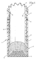
- a vase 1 which consists essentially of a guide sleeve 2.
- the guide sleeve 2 is closed at its bottom 4 so that it is able to hold water safely.
- the bottom 4 is designed so that stem securing recesses 5 are provided, into which the lower ends of the flower stems snap and are thereby held in their position.
- a vase part 3 interacts with the guide sleeve 2 and is arranged within the guide sleeve 2 so as to be adjustable in height.
- the inside of the guide sleeve 2 is preferably equipped with an internal thread 6 and the outside of the vase part 3 with an external thread 7, so that the two components can be continuously adjusted relative to one another.
- protruding cams are arranged on the outside of the vase part 3 and vertically running grooves with horizontally running ring grooves on the inside of the guide sleeve.
- the guide sleeve on the inside and the vase part on the outside.
- a seal 8 is arranged between the inside of the guide sleeve 2 and the outside of the vase part 3.
- the upper edge of the vase is marked 11 and - as shown in FIG. 1 - is equipped with locking cams 12 which also prevent the flowers from slipping Prevent the effects of wind, which is particularly important for graves.
- the vase part 3 consists of a cylinder body 14 which is cylindrical in the drawing, i. H. is round in cross section, but in the same way can also be formed on the outside as a polygonal cylinder body or as a spherical or conical body. So the vase could also be used for home use.
- a sieve that can serve as a "stem sieve", i. H. a grid surface that is able to hold the stems of the flowers set in the desired position.
- this sieve also serves to prevent the vase from being contaminated by leaves or the like.
- a pot-shaped body can also be hung on the support cams 9 and 10 in the vase part 3, so that an additional vase is created here which also serves to hold short-stemmed flowers.
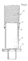
- the vase consists of a vase part 30, which is equipped with an internal thread 60 over its length. This internal thread extends shortly before the lower end of the vase part 30, and in this thread-free lower area a seal 80 is arranged in a corresponding receiving groove, so that the vase part 30 is sealed against the outside of a guide sleeve 20.
- the guide sleeve 20 has external threads 70 in the upper region and is provided with a bottom 40.
- FIG. 2 shows that the reverse arrangement compared to FIG. 1 is also possible.
Abstract
Description
Die Erfindung bezieht sich auf eine Vase gemäß dem Oberbegriff des Patentanspruches 1.The invention relates to a vase according to the preamble of
Aus dem DE-GM 84 26 162 ist eine Blumenvase bekannt, die aus einem Oberteil und einem Fußteil besteht, wobei Oberteil und Fußteil lösbar miteinander verbunden sind und eine Blumenvaseneinheit bilden. Die Gesamthöhe der Blumenvase kann nach Wunsch verstellt werden, indem das Oberteil mehr oder weniger in das Fußteil eingeschoben oder eingeschraubt wird. Über die Ausbildung des für das Einschrauben erforderlichen Gewindes ist dieser Literaturstelle nichts näheres zu entnehmen. Außerdem wird ausgeführt, daß das Oberteil und das Fußteil durch einen Schrumpfsitz miteinander verbunden sein können, so daß das in dem Fußteil befindliche Wasser nicht entweichen kann.A flower vase is known from DE-GM 84 26 162, which consists of an upper part and a foot part, the upper part and foot part being detachably connected to one another and forming a flower vase unit. The total height of the flower vase can be adjusted as desired by pushing or screwing the upper part more or less into the foot part. Nothing in this reference can be found about the formation of the thread required for screwing in. It is also stated that the upper part and the foot part can be connected to one another by a shrink fit so that the water in the foot part cannot escape.
Wie aber das Entweichen des Wassers verhindert werden soll, wenn das Oberteil und das Fußteil miteinander verschraubt sind, wird nicht erläutert. Gerade aber bei langstengeligen und damit großen Blumen ist es aber ein Nachteil, wenn nur in dem Fußteil das Wasser enthalten ist, da man gerade bei Freilandvasen bestrebt ist, möglichst viel Wasservorrat für die Blumen in der Vase unterzubringen.However, how the water should escape when the top part and the foot part are screwed together is not explained. But especially with long-stemmed and thus large flowers, it is a disadvantage if the water is only contained in the foot part, since you are just at Outdoor vases strive to accommodate as much water as possible for the flowers in the vase.
Der Erfindung liegt die Aufgabe zugrunde, die bekannte Einrichtung dahingehend zu verbessern, daß auch im auseinandergeschobenen Zustand der beiden Vasenteile eine Füllung der Vase mit Wasser bis zum oberen Rand hin möglich ist.The invention has for its object to improve the known device in such a way that a filling of the vase with water up to the upper edge is possible even when the two vase parts are pushed apart.
Diese der Erfindung zugrundeliegende Aufgabe wird durch die Lehre des Hauptanspruches gelöst.This object on which the invention is based is achieved by the teaching of the main claim.
Diese der Erfindung zugrundeliegende Aufgabe wird auch durch die Lehre des Anspruches 2 und die Lehre des Anspruches 3 gelöst.This object on which the invention is based is also achieved by the teaching of
Vorteilhafte Ausgestaltungen sind in den Unteransprüchen 4 bis 8 erläutert.Advantageous refinements are explained in
Mit anderen Worten ausgedrückt, wird eine zweiteilige Vase vorgeschlagen, bei welcher das Oberteil weit aus dem Fußteil heraus nach oben verstellt werden kann und wobei trotzdem die so gebildete Gesamtvase voll mit Wasser gefüllt werden kann.In other words, a two-part vase is proposed, in which the upper part can be adjusted upwards far from the foot part and the entire vase thus formed can still be filled with water.
Die Vase kann als Versenkvase, Standvase od. dgl. oder als normale Hausvase eingesetzt werden.The vase can be used as a sink vase, standing vase or the like or as a normal house vase.
Ausführungsbeispiele der Erfindung werden nachfolgend anhand der Zeichnungen erläutert. Die Zeichnungen zeigen in
- Fig. 1 eine erste Ausführungsform der Erfindung und in
- Fig. 2 eine abgeänderte Ausführungsform.
- Fig. 1 shows a first embodiment of the invention and in
- Fig. 2 shows a modified embodiment.
In der Zeichnung ist eine Vase 1 dargestellt, die im wesentlichen aus einer Führungshülse 2 besteht. Die Führungshülse 2 ist an ihrem Boden 4 geschlossen, so daß sie in der Lage ist, Wasser sicher zu halten. Der Boden 4 ist dabei so ausgebildet, daß Stielsicherungsvertiefungen 5 vorgesehen sind, in die die unteren Enden der Blumenstiele einrasten und dadurch in ihrer Stellung gehalten werden.In the drawing, a
Mit der Führungshülse 2 wirkt ein Vasenteil 3 zusammen, das in der Höhe verstellbar innerhalb der Führungshülse 2 angeordnet ist. Vorzugsweise wird für diese Verstellmöglichkeit die Innenseite der Führungshülse 2 mit einem Innengewinde 6 ausgerüstet und die Außenseite des Vasenteiles 3 mit einem Außengewinde 7, so daß ein stufenloses Verstellen der beiden Bauteile gegeneinander möglich ist. Es ist natürlich auch möglich, eine stufenweise Verstellung vorzusehen, wobei dann an der Außenseite des Vasenteiles 3 vorstehende Nocken angeordnet werden und an der Innenseite der Führungshülse 2 senkrecht verlaufende Nuten mit horizontal verlaufenden Ringnuten. Auch ist es möglich, die Führungshülse innen und das Vasenteil außen anzuordnen.A vase part 3 interacts with the
Um eine sichere Halterung des Wassers in der Führungshülse 2 und dem Vasenteil 3 zu gewährleisten, und zwar auch dann, wenn das Vasenteil 3 nach oben vorgezogen ist, ist zwischen der Innenseite der Führungshülse 2 und der Außenseite des Vasenteiles 3 eine Dichtung 8 angeordnet.In order to ensure a secure holding of the water in the
Der obere Vasenrand ist mit 11 bzeichnet und - wie dies die Fig. 1 zeigt - mit Arretiernocken 12 ausgerüstet, die ein Verrutschen der Blumen auch bei Windeinwirkung verhindern, was insbesondere bei Grabstellen von großer Bedeutung ist.The upper edge of the vase is marked 11 and - as shown in FIG. 1 - is equipped with
Das Vasenteil 3 besteht aus einem Zylinderkörper 14, der in der Zeichnung zylindrisch, d. h. im Querschnitt rund ausgebildet ist, aber in gleicher Weise auch außen als polygonaler Zylinderkörper oder als Kugel- bzw. Kegelkörper ausgebildet sein kann. Somit wäre die Vase auch für den Hausgebrauch verwendbar.The vase part 3 consists of a
Bei 9 und 10 sind im Inneren des Vasenteiles 3 angeordnete Auflagenocken angedeutet, die der Aufnahme eines Siebes dienen, das als "Stielsieb" dienen kann, d. h. einer Gitterfläche, die in der Lage ist, die Stiele der eingestellten Blumen in der gewollten Lage zu halten. Bei Nichtgebrauch der Vase dient dieses Sieb gleichzeitig dazu, ein Verschmutzen der Vase durch Blätter od. dgl. zu verhindern.At 9 and 10 arranged in the interior of the vase part 3 support cams are indicated, which serve to hold a sieve that can serve as a "stem sieve", i. H. a grid surface that is able to hold the stems of the flowers set in the desired position. When the vase is not in use, this sieve also serves to prevent the vase from being contaminated by leaves or the like.
Auf die Auflagenocken 9 und 10 kann aber auch ein topfförmiger Körper in das Vasenteil 3 eingehängt werden, so daß hier eine Zusatzvase geschaffen wird, die der Halterung auch kurzstieliger Blumen dient.However, a pot-shaped body can also be hung on the
Bei der in Fig. 2 dargestellten Ausführungsform besteht die Vase aus einem Vasenteil 30, das über seine Länge gesehen mit Innengewinde 60 ausgerüstet ist. Dieses Innengewinde reicht bis kurz vor das untere Ende des Vasenteiles 30, und in diesem gewindefreien unteren Bereich ist eine Dichtung 80 in einer entsprechenden Aufnahmenut angeordnet, so daß eine abgedichtete Anlage des Vasenteiles 30 an der Außenseite einer Führungshülse 20 erfolgt. Die Führungshülse 20 weist im oberen Bereich Außengewinde 70 auf und ist mit einem Boden 40 versehen.In the embodiment shown in FIG. 2, the vase consists of a
Die Fig. 2 zeigt, daß auch die umgekehrte Anordnung gegenüber Fig. 1 möglich ist.FIG. 2 shows that the reverse arrangement compared to FIG. 1 is also possible.
Schließlich ist es möglich, anstelle des durchgehenden Innengewindes auch nur Gewindesegmente einzusetzen, die mit dem Außengewinde 70 oder dem Außengewinde 7 gemäß Fig. 1 kämmen.Finally, instead of the continuous internal thread, it is also possible to use only thread segments which mesh with the
Claims (8)
Applications Claiming Priority (4)
| Application Number | Priority Date | Filing Date | Title |
|---|---|---|---|
| DE3822561 | 1988-07-04 | ||
| DE3822561 | 1988-07-04 | ||
| DE19883826334 DE3826334C1 (en) | 1988-07-04 | 1988-08-03 | |
| DE3826334 | 1988-08-03 |
Publications (2)
| Publication Number | Publication Date |
|---|---|
| EP0349932A2 true EP0349932A2 (en) | 1990-01-10 |
| EP0349932A3 EP0349932A3 (en) | 1990-05-02 |
Family
ID=25869722
Family Applications (1)
| Application Number | Title | Priority Date | Filing Date |
|---|---|---|---|
| EP89112023A Withdrawn EP0349932A3 (en) | 1988-07-04 | 1989-07-01 | Vase |
Country Status (2)
| Country | Link |
|---|---|
| EP (1) | EP0349932A3 (en) |
| DE (1) | DE3826334C1 (en) |
Families Citing this family (3)
| Publication number | Priority date | Publication date | Assignee | Title |
|---|---|---|---|---|
| DE3931464C1 (en) * | 1989-07-28 | 1990-07-26 | Helmut 4453 Langen De Appelrath | |
| DE4313069C2 (en) * | 1993-04-21 | 2001-04-19 | Helmut Appelrath | Bowl vase |
| US6092330A (en) * | 1998-09-18 | 2000-07-25 | Pratt; Robert | Memorial year round flower display |
Citations (7)
| Publication number | Priority date | Publication date | Assignee | Title |
|---|---|---|---|---|
| FR340489A (en) * | 1904-02-17 | 1904-07-07 | Georges De Wattripont | Removable and expandable flower holder for vases of all sizes and shapes |
| US1714193A (en) * | 1925-09-30 | 1929-05-21 | Edwin E Slick | Vase for flowers and the like |
| DE485794C (en) * | 1929-11-05 | Heinrich Suter | Vase | |
| GB362737A (en) * | 1931-01-20 | 1931-12-10 | Frederic Atkinson | Improvements in rose or flower bowls and similar receptacles |
| US3369321A (en) * | 1965-08-05 | 1968-02-20 | Zachariah D. Blackistone Jr. | Ground line cemetery vase |
| AT310487B (en) * | 1972-02-11 | 1973-10-10 | Beyrhofer Ges M B H | Vase |
| DE8426162U1 (en) * | 1984-09-05 | 1985-01-03 | Henke, Jürgen, 3013 Barsinghausen | Vase |
Family Cites Families (2)
| Publication number | Priority date | Publication date | Assignee | Title |
|---|---|---|---|---|
| DE1818495U (en) * | 1960-07-25 | 1960-09-22 | Laeisz & Lueders | VASE. |
| DE1916951A1 (en) * | 1969-04-02 | 1970-10-15 | Petry Dr Ing Hans | Electromagnetic relay combined with a current transformer for network protection |
-
1988
- 1988-08-03 DE DE19883826334 patent/DE3826334C1/de not_active Expired
-
1989
- 1989-07-01 EP EP89112023A patent/EP0349932A3/en not_active Withdrawn
Patent Citations (7)
| Publication number | Priority date | Publication date | Assignee | Title |
|---|---|---|---|---|
| DE485794C (en) * | 1929-11-05 | Heinrich Suter | Vase | |
| FR340489A (en) * | 1904-02-17 | 1904-07-07 | Georges De Wattripont | Removable and expandable flower holder for vases of all sizes and shapes |
| US1714193A (en) * | 1925-09-30 | 1929-05-21 | Edwin E Slick | Vase for flowers and the like |
| GB362737A (en) * | 1931-01-20 | 1931-12-10 | Frederic Atkinson | Improvements in rose or flower bowls and similar receptacles |
| US3369321A (en) * | 1965-08-05 | 1968-02-20 | Zachariah D. Blackistone Jr. | Ground line cemetery vase |
| AT310487B (en) * | 1972-02-11 | 1973-10-10 | Beyrhofer Ges M B H | Vase |
| DE8426162U1 (en) * | 1984-09-05 | 1985-01-03 | Henke, Jürgen, 3013 Barsinghausen | Vase |
Also Published As
| Publication number | Publication date |
|---|---|
| EP0349932A3 (en) | 1990-05-02 |
| DE3826334C1 (en) | 1989-12-21 |
Similar Documents
| Publication | Publication Date | Title |
|---|---|---|
| DE10108965A1 (en) | bone screw | |
| DE3909580A1 (en) | ENOSSAL IMPLANT WITH ELASTIC INTERMEDIATE ELEMENT AND METAL DISTANCE SLEEVE | |
| DE3242059C2 (en) | ||
| EP0349932A2 (en) | Vase | |
| DE2835939C2 (en) | Holder for a support rod for tall potted plants | |
| DE3931464C1 (en) | ||
| EP1245741A2 (en) | Sanitary fitting | |
| EP1338223A2 (en) | Insertion device,male element and arrangement for supporting objects using an insertion device and a male element | |
| AT411421B (en) | HEIGHT-ADJUSTABLE SHOWER TRAY | |
| DE3015065A1 (en) | LOCKING DEVICE FOR FLAKONS | |
| EP1245742A2 (en) | Sanitary fitting | |
| CH709249A2 (en) | Cultivating device. | |
| EP1087686B1 (en) | Device for maintaining and adjusting platelike elements | |
| DE3316378A1 (en) | Border for plant installations | |
| DE19828746B4 (en) | Tour guide | |
| DE3414888A1 (en) | Adjustable-height erection and damping device | |
| AT510889A1 (en) | DEVICE FOR PRODUCING SHOWER TRAYS OR BOXES | |
| EP0607462A1 (en) | False floor | |
| DE3025365C2 (en) | ||
| DE102014119316A1 (en) | Grave vase for cut flowers with a slim vase pot | |
| DE3618709C2 (en) | ||
| EP0915219A1 (en) | Column base | |
| DE2801773B1 (en) | Carrying device for furniture components | |
| EP0396064A2 (en) | Support, particularly for false floor | |
| CH679324A5 (en) | Screwed-joint locking device - is cup-shaped with slots in wall forming axial spring grip tongues |
Legal Events
| Date | Code | Title | Description |
|---|---|---|---|
| PUAI | Public reference made under article 153(3) epc to a published international application that has entered the european phase |
Free format text: ORIGINAL CODE: 0009012 |
|
| AK | Designated contracting states |
Kind code of ref document: A2 Designated state(s): AT BE CH DE FR GB IT LI NL SE |
|
| PUAL | Search report despatched |
Free format text: ORIGINAL CODE: 0009013 |
|
| AK | Designated contracting states |
Kind code of ref document: A3 Designated state(s): AT BE CH DE FR GB IT LI NL SE |
|
| 17P | Request for examination filed |
Effective date: 19901005 |
|
| 17Q | First examination report despatched |
Effective date: 19911119 |
|
| STAA | Information on the status of an ep patent application or granted ep patent |
Free format text: STATUS: THE APPLICATION IS DEEMED TO BE WITHDRAWN |
|
| 18D | Application deemed to be withdrawn |
Effective date: 19920204 |