EP0349870B1 - Dispensing device for shaving units - Google Patents
Dispensing device for shaving units Download PDFInfo
- Publication number
- EP0349870B1 EP0349870B1 EP89111562A EP89111562A EP0349870B1 EP 0349870 B1 EP0349870 B1 EP 0349870B1 EP 89111562 A EP89111562 A EP 89111562A EP 89111562 A EP89111562 A EP 89111562A EP 0349870 B1 EP0349870 B1 EP 0349870B1
- Authority
- EP
- European Patent Office
- Prior art keywords
- razor blade
- handle
- dispenser housing
- dispenser
- blade units
- Prior art date
- Legal status (The legal status is an assumption and is not a legal conclusion. Google has not performed a legal analysis and makes no representation as to the accuracy of the status listed.)
- Expired - Lifetime
Links
Images


Classifications
-
- B—PERFORMING OPERATIONS; TRANSPORTING
- B26—HAND CUTTING TOOLS; CUTTING; SEVERING
- B26B—HAND-HELD CUTTING TOOLS NOT OTHERWISE PROVIDED FOR
- B26B21/00—Razors of the open or knife type; Safety razors or other shaving implements of the planing type; Hair-trimming devices involving a razor-blade; Equipment therefor
- B26B21/08—Razors of the open or knife type; Safety razors or other shaving implements of the planing type; Hair-trimming devices involving a razor-blade; Equipment therefor involving changeable blades
- B26B21/14—Safety razors with one or more blades arranged transversely to the handle
- B26B21/24—Safety razors with one or more blades arranged transversely to the handle of the magazine type; of the injector type
-
- A—HUMAN NECESSITIES
- A45—HAND OR TRAVELLING ARTICLES
- A45D—HAIRDRESSING OR SHAVING EQUIPMENT; EQUIPMENT FOR COSMETICS OR COSMETIC TREATMENTS, e.g. FOR MANICURING OR PEDICURING
- A45D27/00—Shaving accessories
- A45D27/22—Containers or carriers for storing shaving appliances
- A45D27/225—Containers or carriers for storing shaving appliances for storing razor blade cartridges, e.g. after use
-
- B—PERFORMING OPERATIONS; TRANSPORTING
- B26—HAND CUTTING TOOLS; CUTTING; SEVERING
- B26B—HAND-HELD CUTTING TOOLS NOT OTHERWISE PROVIDED FOR
- B26B21/00—Razors of the open or knife type; Safety razors or other shaving implements of the planing type; Hair-trimming devices involving a razor-blade; Equipment therefor
- B26B21/40—Details or accessories
- B26B21/52—Handles, e.g. tiltable, flexible
- B26B21/521—Connection details, e.g. connection to razor heads
Definitions
- the invention relates to a dispenser system for razor blade units, several of which are arranged one behind the other in a dispenser housing, one behind the other and can be removed and, if necessary, reinserted by means of a handle to form a razor, the head of the handle and the razor blade units having interlocking devices which correspond to one another and the razor blade units are perpendicular whose longitudinal extensions and in the plane formed by them in their entirety are arranged displaceably in the dispenser housing and the foremost, advanced razor blade unit for removal is located in the removal position common to all razor blade units by means of the handle.
- razor blade units are understood to mean razor heads in which the single or double razor blades are embedded in a non-detachable manner in a plastic body and which can be attached to a head of a handle, for which purpose the handle head and the razor blade units have interlocking devices which correspond to one another.
- the handle of the razor has a corresponding actuating button with which the locking device of the handle can be brought into the unlocked position. In this unlocking position, the handle can be attached to the respective razor blade unit and locked with it, so that the razor blade unit can be removed from the corresponding compartment of the dispenser housing by means of the handle attached to it.
- the razor thus formed can then be used for shaving. Replace a used razor blade unit in the reverse way.
- a dispenser system for razor blade units is known from US Pat. No. 3,833,146, which has a plurality of razor blade units which are arranged one behind the other in a dispenser housing and which can be removed and, if necessary, reinserted by means of a handle to form a razor.
- the connection between the handle and a razor blade unit to be removed is formed in that a longitudinally extending, undercut groove is arranged in the razor blade unit, into which a corresponding web of the handle can be inserted.
- the web of the handle and the groove in the razor blade unit form a corresponding locking device.
- the dispenser system has a removal opening arranged on the side wall for removing the razor blade units on.
- the object of the invention is to create a dispenser system for razor blade units in which the handle of the razor can be attached in a simple manner to the razor blade unit to be removed from the dispenser housing.
- a removal opening is arranged on an end face of the dispenser housing and that the dispenser housing has a guide device for the head of the handle which ends in the area of the removal opening and which brings the locking device of the handle into the unlocking position when it is guided along and that on reaching the removal position releases the locking device so that it passes into the locking position forming the basic position and thereby locks with the razor blade unit to be removed.
- a dispenser system designed according to this technical teaching has the advantage that the razor blade units can be removed from the dispenser housing in a very simple manner by means of the handle. For this purpose, it is only necessary to insert the head of the handle into the guide device of the dispenser housing and guide it to the removal position, where the locking device of the handle automatically locks with the locking device of the razor blade unit to be removed and thus forms the ready-to-use razor. Its razor blade unit located at the front end of the handle then only has to be removed from the dispenser housing. Since the razor blade units are slidably arranged in the dispenser housing, the next razor blade unit moves into the removal position at the removal opening so that it can be removed next.
- the guide device is preferably arranged on the top of the dispenser housing and parallel to the direction of displacement of the razor blade units. This represents a simple possibility for attaching the guide device to the dispenser housing.
- a compression spring is preferably arranged between the last razor blade unit and the end wall of the dispenser housing opposite the removal opening.
- the handle has a manually operable device for transferring the locking device into the unlock position. In this way, the handle can be "disposed of" very easily by a used razor blade unit.
- the dispenser housing has a feed opening on the end face opposite the removal opening for reinserting used razor blade units, the guide device beginning in the region of this feed opening opening the handle from the feed opening to the feed opening Removal opening after inserting the razor blade unit brings the locking device of the handle into the unlocking position and thereby releases the connection to the razor blade unit to be reinserted.
- a used razor blade unit can be replaced very easily and very quickly by an as yet unused razor blade unit by first feeding the used razor blade unit to the feed opening of the dispenser housing.
- the guide device starting here unlocks the handle from the re-inserted razor blade unit by moving the handle in the direction of the removal opening.
- a preferred embodiment of the guiding and locking mechanism of the dispenser system proposes that the locking device of the handle consists of two arms which can be pivoted in opposite directions against the force of a spring and which have claws directed at the front ends against the respective pivoting direction, so that the razor blade units are connected to the Claws have corresponding receiving bores and that the guide device on the top of the dispenser housing has two spaced parallel C-shaped guide channels for receiving the claws, the distance between the two guide channels being such that the arms are pivoted into the unlocked position, and wherein the guide troughs in the area of the opening (s) are angled to the razor blade unit to be removed or reinserted into the latching or unlatching position.
- the claws which are aligned parallel to the cutting edge of the razor blade, serve as a pivot axis for a pivoting head shaver which adapts very precisely to the contours of the face.
- the arms are preferably pivotable toward one another and the claws are directed away from one another outward. In this way, a relatively large distance between the claws can be achieved, which ensures good stability between the handle and the razor blade unit attached to it.
- the dispenser housing in the area of the opening (s) have inclined guides for the locking device of the handle with respect to the direction of displacement of the razor blade units. These guides in particular in the area of the feed opening ensure that when the razor blade units to be reinserted, the locking device arranged on the handle is gradually moved into the unlocked position. Following the guides, the guide channels of the preferred embodiment of the guide device then follow.
- the dispenser housing be designed as a substantially flat hollow cuboid, the opposite open end faces of which define a feed opening for reinserting used razor blade units and the removal opening for the still unused razor blade units, and the top of the dispenser housing defines one of them
- Feed opening to the removal opening has a continuous opening, which is widened trapezoidal in width at the ends in the area of the supply opening and the removal opening, and wherein the edges of the dispenser housing that delimit the opening and parallel to one another in the central region define rails
- the locking device of the handle consists of two opposites the force of a spring inwardly towards each other to pivotable arms which are directed away from each other at the front ends and have claws corresponding to receiving bores in the razor blade units and each have on the outer edge a guide recess corresponding to the corresponding rail of the dispenser housing.
- a used razor blade unit can be replaced very simply and quickly by an as yet unused razor blade unit by first feeding the used razor blade unit by means of the handle to the feed opening of the dispenser housing.
- the unlocking device for the pivotable arms of the handle is through the edge-like Rails of the dispenser housing and formed by the guide recesses in the arms of the locking device by the guide recesses engage in the rails delimiting the opening. Due to the trapezoidal tapering of this opening in the area of the feed opening, the arms are pivoted inward so that the claws disengage from the receiving bores in the razor blade unit.
- the razor blade units already located in the dispenser housing are simultaneously transported by one position, so that the used razor blade unit that has just been inserted assumes the last position.
- the handle is then moved in the direction of the removal opening and picks up the razor blade unit which is ready for removal and is still unused.
- the "disposal" of the used razor blade unit as well as the as yet unused razor blade unit can be carried out in one go, ie in one continuous movement.
- Reinstalling the used razor blade unit also has the effect that the razor blade units located in the dispenser housing are moved in their entirety, so that the foremost razor blade unit is brought into the removal position.
- the dispenser system designed in this way is characterized by a structurally simple structure and very good functionality with a high level of functional reliability. The razor blade units are picked up and released very safely.
- the upper side of the dispenser housing with the rails facing upward and / or the receiving channel for the razor blade units is inside with respect to the plane of insertion and ejection of the razor blade units into the feed opening or out of the removal opening in the central region of the opening of the dispenser housing is displaced downwards in such a way that the arms of the locking device of the handle with their claws can be moved from this rear position to the front removal position via the intermediate razor blade units after the used razor blade unit has been released.
- both the rails and the receiving channel are offset upwards or downwards, so that after a short distance the arms with their claws have reached such a height above the razor blade units that they can be guided over them.
- the razor blade units are guided laterally within the dispenser housing in the area of the side walls thereof by guide rails.
- the path along which the razor blade units move is predetermined in a technically simple manner. In particular, this makes it possible in a technically simple manner to lower the receiving channel for the razor blade units downwards in the central region.
- the dispenser housing it is composed of two halves along the longitudinal central axis. This has the advantage that the dispenser housing can be manufactured very simply by injection molding.
- the dispenser housing has reinforcing ribs running transversely on the outside. These reinforcing ribs prevent the upper, free legs from deforming inwards when the dispenser housing is sprayed, and the dispenser housing as such is therefore unusable.
- spring-like cams are arranged in the dispenser housing in the region of the opening (s), which hold the razor blade units within the dispenser housing, but after overcoming the holding force exerted by them, can be passed through the respective razor blade unit to be removed or reinserted.
- the razor blade units each have a central web and that the head of the handle has a protruding and corresponding fork that receives the central web and that is spring-loaded in the direction of the head of the handle, the advantage is achieved with an oscillating head shaver that the razor blade unit always assumes a defined starting position, into which it springs back automatically when deflected.
- the guide device preferably has guide strips which interact with the head of the handle.
- the invention proposes that a compression spring is arranged between the last unused and the first used razor blade unit. This ensures that the razor blade units are held firmly within the dispenser housing without, for example, rattling noises when the dispenser housing moves.
- the compression spring ensures that the razor blade unit to be removed is located exactly in the removal position.
- the compression spring is preferably designed such that it cannot pass through the spring-like cams. In addition to the advantage that gaps existing between the razor blade units are compensated for, this also has the main advantage that if there are only used razor blade units located in the dispenser housing, these are removed again, since the compression spring now located at the front acts as a lock and cannot be removed and indicates to the user that he has no unused razor blade unit available.
- FIGS. 11 to 20 show a first embodiment and in FIGS. 11 to 20 a second embodiment of a dispenser system.
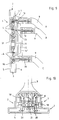
- a dispenser housing 1 made of a molded plastic part in accordance with the first embodiment of the dispenser system is designed as a flat cuboid. On the face side, the dispenser housing 1 has a feed opening 2 on one side (top in FIG. 1) and a removal opening 3 for razor blade units 4 on the opposite side (bottom in FIG. 1), which, however, is not shown in FIGS. 1 to 3 are. The dispenser housing 1 is thus shown in the empty state.
- the guide device 7 initially consists of two mutually parallel guide channels 11 which, as can be seen in particular in FIG. 3, have a C-shape and are at a certain distance from one another. These guide channels 11 extend almost over the entire length of the dispenser housing 1 and are angled at the end toward the top 6, as can also be seen in the sectional view according to FIG. 9, for example.
- a guide bar 12 is formed on the outside of the guide troughs 11 and is chamfered at the end. On the outside of this guide bar 12, a further guide bar 12 'is formed, which is slightly higher than the guide bar 12th
- the top 6 of the dispenser housing 1 has a trapezoidal recess 13.
- the sloping edges serve as guides 14. These end in the region of the guide grooves 11, the upper side 6 of the dispenser housing 1 here having a passage slot 15.
- a corresponding recess 13 ' is provided in the region of the removal opening 3. There, too, the top 6 of the dispenser housing 1 has a passage slot 15 '.
- the head 8 of the handle 9 for the shaver 10 is shown in particular.
- this head 8 are in Bear 17 two arms 18 pivoted inwards. 4 shows both the basic position and the inner pivoting position of the arms 18.
- a U-shaped spring 19 is arranged, which presses the arms 18 outwards to bear against the head 8 of the handle 9.
- the free ends of the arms 18 each have an outwardly directed peg-shaped claw 20.
- a fork 21 can be seen in FIG. 4, which is mounted in the head 8 so as to be longitudinally displaceable, a spring 22 pressing the fork 21 into the forward basic position.
- the spring 22 is integrally formed with the U-shaped spring 19.
- the head is closed by a cover 23. This has been omitted in the illustration according to FIG. 4 in order to be able to recognize the parts arranged inside the head 8.
- Fig. 6 shows a razor blade unit 4 of the usual type, i.e. two razor blades are embedded in a plastic body 24. Only the rear of the razor blade unit 4 shown in FIG. 6 is interesting. It shows that two webs 26 are formed on the plastic body 24, each of which has a receiving bore 27 corresponding to the peg-shaped claws 20. Furthermore, a central web 28 is formed on the plastic body 24, which corresponds to the fork 21 of the handle 9 in such a way that the fork 21 receives the central web 28 in the assembly position.
- FIGS. 7 and 8 This assembly position for forming a complete shaver 10 is shown in FIGS. 7 and 8.
- Fig. 7 it can be seen that after the arms 18 of the handle 9 have been briefly pivoted inwards, their claws 20 are received by the receiving bores 27 in the razor blade unit 4 and form as an axis of rotation for a so-called oscillating head shaver.
- the fork 21 presses the Center bar 28 and thus the entire razor blade unit 4 away from the head 8 of the handle 9, so that the razor blade unit 4 assumes a central position into which it returns resiliently when deflected.
- the description shows that the arms 18 with the claws 20 form a locking device 29 assigned to the head 8 of the handle 9 and the receiving bore 27 formed in the webs 26 form a locking device 30 corresponding to the razor blade unit 4.
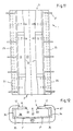
- the dispenser housing 1 filled with a total of five razor blade units 4 can be seen in FIG. 9. They are held by the cams 16.
- a compression spring 31 is arranged between the two lower razor blade units 4 and the three upper razor blade units 4, which presses the razor blade units 4 outwards against the contact with the cams 16.
- the two lower razor blade units 4 are still unused copies, while the three upper razor blade units 4 are used and reused.
- a used razor blade unit 4 is to be replaced by an as yet unused razor blade unit 4.
- the used razor blade unit 4 still connected to the handle 9 is inserted with the handle 9 into the feed opening 2 of the dispenser housing 1 (in FIG. 9 from above).
- the arms 18 come to bear on the conically narrowing guides 14 in the recess 13 in such a way that the arms 18 are pivoted inwards. This can also be seen, for example, in FIG. 10, but without the corresponding razor blade unit 4.
- the claws 20 of the arms 18 disengage from the receiving bores 17 in the razor blade unit and thus release them.
- the used razor blade unit 4 has thus reached its dispensing position after it has moved the underlying razor blade units 4 by one position each, so that the still unused razor blade unit 4 at the front assumes the removal position at the removal opening 3.
- the handle 9 takes position A after unlocking in Fig. 9. Then the claws 20 of the arms 18 of the handle 9 are guided through the passage slot 15 upwards to the top 6 of the dispenser housing 1 into the guide channels 11 and are displaced along these guide channels 11 to the removal opening 3. This shift position is indicated by position B. Due to the distance between the guide channels 11, the arms 18 remain in the inwardly pivoted position. During the displacement movement, the guide strips 12, 12 'in cooperation with the head 8 of the handle 9 assume guiding properties.
- the claws of the arms 18 ' enter the dispenser housing 1 through the passage slot 15'. In this position, the peg-like claws 20, which are still pivoted inward, are aligned with the receiving bores 27 of the razor blade unit. This is indicated by position C in FIG. 9.
- the fork 21 takes the central web 28 and thus the razor blade unit 4 with it.
- the arms 18 can gradually move outwards under the force of the spring 19 and come in the receiving bores 27 of the razor blade unit 4 to lie. In this situation, the razor blade unit 4 is firmly connected to the head 8 of the handle 9, so that a corresponding razor 10 is formed. The razor blade unit 4 can then be completely pulled out of the dispenser housing 1.
- this also has a plastic dispenser housing 1.
- This is the basic shape also as a flat hollow cuboid and is composed of two dispenser housing halves 1 ', 1 ⁇ along the longitudinal central axis, as can be seen in particular in Fig. 12.
- the end faces of the elongated hollow cuboid are each open and define the feed opening 2 and the removal opening 3 for the razor blade units 4.
- the dispenser housing 1 has a longitudinal opening 32 which extends from the feed opening 2 to the removal opening 3 .
- the opening 32 is defined by the upper edges 33 of the two dispenser housing halves 1 ', 1 ⁇ , these edges forming 33 rails, the purpose of which will be explained below.
- FIG. 1 As can be seen in the plan view according to FIG.
- the two edges 33 initially run parallel for a short distance.
- the edges 33 then bend towards the longitudinal center plane and reduce the width of the opening 32.
- the edges 33 then run parallel again in order to bend outwards again in the region of the removal opening 3 and then run again parallel with the original width of the opening 32.
- spring-like cams 16 are arranged within the dispenser housing 1 in the region of the two openings 2, 3, which can be passed through the razor blade units 4, but fix them in between such that they do not fall out.
- the dispenser housing 1 also has longitudinal guide strips 12. Finally, the dispenser housing 1 is provided with transverse reinforcing ribs 37.
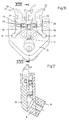
- This dispenser housing 1 includes a head 8 of a razor, as shown in FIGS. 16 and 17.
- the handle 9 is only indicated.
- two arms 18 are supported in bearings 17. These can be pivoted inward against the force of a spring 19 in the form of a helical spring, the basic position being shown with solid lines and the inwardly pivoted position with dashed lines.
- the arms 18 each have a claw 20, the two claws 20 being directed outwards and corresponding to corresponding receiving bores 27 in the plastic body 24 of the razor blade unit 4 and defining a pivot axis.
- the outer edges 38 of the two arms 18 each have a guide recess 39 which correspond to the edges 33 of the dispenser housing 1.
- the head 8 also has a fork 21 which is pressed forward by means of a spring 22, which is also designed as a helical spring.
- the functional mechanism is the same as in the first embodiment of the head 8.
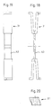
- a compression spring 31 is provided between the used and the unused razor blade units 4. This is shown enlarged in FIGS. 18 to 20.
- the compression spring 31 has spring areas in the form of fork springs, which are connected to one another by an intermediate web 40.
- the side profile of the compression spring 31 corresponds to the cams 16 arranged inside the dispenser housing 1, in a manner as will be explained below.
- a used razor blade unit 4 is to be replaced by an as yet unused razor blade unit 4.
- the used razor blade unit 4 still connected to the handle 9 is inserted with the handle 9 into the feed opening 2 of the dispenser housing 1 (in FIG. 14 from below).
- the claws 20 of the arms 18 of the head 8 of the shaving apparatus engage in the corresponding receiving bores 27 in the plastic body 24 of the razor blade unit 4.
- the edges 33 of the dispenser housing 1 initially take up the guide recesses 39 in the arms 18 of the head 8. The arms 18 are still in their basic and thus in the engaged position with the razor blade unit 4.
- the edges 33 bend inwards, so that the arms 18 gradually pivot inwards and thus come out of engagement with the receiving bores 27 of the razor blade unit 4.
- the receiving channel 36 bends downwards due to the arrangement of the guide rails 35, in order finally to pass through the spring-like cams 16 in the region of the feed opening 2.
- the inserted razor blade unit 4 presses the compression spring 31 in the rearmost position and, together with the razor blade unit 4 in front of it, pushes it forward by one position. In this position, the claws 20 of the arms 18 are already out of engagement with the receiving bores 27 of the razor blade unit 4.
- the arms 18 with their claws 20 of the head 8 then slide forward over the razor blade unit 4 in front to the removal opening 3.
- the foremost razor blade unit 4 has already been lifted there by the feed through the guide rail 35 located there.
- the arms 18 of the head 8 engage in the razor blade unit, in order to then latch into the razor blade unit 4 after passing through the two cams 16 and the funnel-shaped extension, when the arms 18 return to their basic position due to the spring 19 move.
- the still unused razor blade unit 4 can be removed from the dispenser housing 1.
- the cams 16 in the region of the feed opening 2 are designed such that pulling out of a used razor blade unit 4 to the rear is prevented by the rearmost razor blade unit 4 abutting these cams 16.
- the compression spring 31 reaches the foremost position and thereby abuts the cams 16 in the region of the removal opening 3 in such a way that it cannot pass through them.
- the compression spring 31 has the function of a lock, which prevents the foremost of the used razor blade units 4 from reaching the removal position and being erroneously removed and viewed as an unused razor blade unit 4. This situation is shown in Fig. 15.
Abstract
Description
Die Erfindung betrifft ein Spendersystem für Rasierklingeneinheiten, von denen mehrere in einem Spendergehäuse parallel aneinanderliegend hintereinander angeordnet und mittels eines Handgriffs zum Bilden eines Rasierapparates jeweils entnehmbar und gegebenenfalls wiedereinsetzbar sind, wobei der Kopf des Handgriffs sowie die Rasierklingeneinheiten miteinander korrespondierende Verriegelungseinrichtungen aufweisen, die Rasierklingeneinheiten senkrecht zu deren Längserstreckungen sowie in der durch sie gebildeten Ebene in ihrer Gesamtheit verschiebbar im Spendergehäuse angeordnet sind und sich die jeweils vorderste, nachgerückte Rasierklingeneinheit zu deren Entnahme mittels des Handgriffs in der für sämtliche Rasierklingeneinheiten gemeinsamen Entnahmeposition befindet.The invention relates to a dispenser system for razor blade units, several of which are arranged one behind the other in a dispenser housing, one behind the other and can be removed and, if necessary, reinserted by means of a handle to form a razor, the head of the handle and the razor blade units having interlocking devices which correspond to one another and the razor blade units are perpendicular whose longitudinal extensions and in the plane formed by them in their entirety are arranged displaceably in the dispenser housing and the foremost, advanced razor blade unit for removal is located in the removal position common to all razor blade units by means of the handle.
Spendersysteme für Rasierklingeneinheiten sind bekannt. Dabei werden unter Rasierklingeneinheiten Rasierköpfe verstanden, bei denen die Einfach- bzw. Doppelrasierklingen unlösbar in einem Kunststoffkörper eingebettet sind und die an einem Kopf eines Handgriffs befestigt werden können, wobei zu diesem Zweck der Handgriffkopf sowie die Rasierklingeneinheiten miteinander korrespondierende Verriegelungseinrichtungen aufweisen.Dispenser systems for razor blade units are known. In this context, razor blade units are understood to mean razor heads in which the single or double razor blades are embedded in a non-detachable manner in a plastic body and which can be attached to a head of a handle, for which purpose the handle head and the razor blade units have interlocking devices which correspond to one another.
Bei dem bekannten Spendersystem sind mehrere Rasierklingeneinheiten in einem Spendergehäuse in entsprechenden Fächern angeordnet. Um die einzelnen Rasierklingeneinheiten aus dem Spendergehäuse herausnehmen und gegebenenfalls wiedereinsetzen zu können, weist der Handgriff des Rasierapparates einen entsprechenden Betätigungsknopf auf, mit dem die Verriegelungseinrichtung des Handgriffs in die Entriegelungsstellung gebracht werden kann. In dieser Entriegelungsstellung kann der Handgriff an die jeweils zu entnehmende Rasierklingeneinheit angesetzt und mit dieser verriegelt werden, so daß die Rasierklingeneinheit mittels des daran befestigten Handgriffes aus dem entsprechenden Fach des Spendergehäuses herausgenommen werden kann. Der so gebildete Rasierapparat kann dann für die Rasur verwendet werden. Das Wiedereinsetzen einer verbrauchten Rasierklingeneinheit erfolgt in der umgekehrten Weise.In the known dispenser system, several razor blade units are arranged in corresponding compartments in a dispenser housing. In order to be able to remove the individual razor blade units from the dispenser housing and, if necessary, to reinsert them, the handle of the razor has a corresponding actuating button with which the locking device of the handle can be brought into the unlocked position. In this unlocking position, the handle can be attached to the respective razor blade unit and locked with it, so that the razor blade unit can be removed from the corresponding compartment of the dispenser housing by means of the handle attached to it. The razor thus formed can then be used for shaving. Replace a used razor blade unit in the reverse way.
Bei diesem bekannten Spendersystem für Rasierklingeneinheiten ist von Nachteil, daß die Befestigung des Handgriffkopfes an der jeweils zu entnehmenden Rasierklingeneinheit nicht immer einfach ist und etwas Geschick erfordert, da die Verriegelungseinrichtung des Handgriffkopfes exakt in die Verriegelungsposition mit der entsprechenden Verriegelungseinrichtung der Rasierklingeneinheit gebracht werden muß. Insbesondere bei Menschen, deren Hände etwas zittern oder die schlecht sehen, kann dies zu erheblichen Schwierigkeiten führen.In this known dispenser system for razor blade units, it is disadvantageous that the attachment of the handle head to the razor blade unit to be removed in each case is not always easy and requires some skill, since the locking device of the handle head must be brought exactly into the locking position with the corresponding locking device of the razor blade unit. This can lead to considerable difficulties, especially for people whose hands are trembling or who see poorly.
Beispielsweise ist aus der US-A 3,833,146 ein Spendersystem für Rasierklingeneinheiten bekannt, welches mehrere in einem Spendergehäuse parallel aneinanderliegend hintereinander angeordnete und mittels eines Handgriffs zum Bilden eines Rasierapparates jeweils entnehmbare und ggf. wiedereinsetzbare Rasierklingeneinheiten aufweist. Bei diesem vorbekannten Spendersystem wird die Verbindung zwischen dem Handgriff und einer zu entnehmenden Rasierklingeneinheit dadurch gebildet, daß in der Rasierklingeneinheit eine in Längsrichtung verlaufende, hinterschnittene Nut angeordnet ist, in welche ein hierzu korrespondierender Steg des Handgriffs einschiebbar ist. Der Steg des Handgriffs und die Nut in der Rasierklingeneinheit bilden eine miteinander korrespondierende Verriegelungseinrichtung. Das Spendersystem weist zur Entnahme der Rasierklingeneinheiten eine an der Seitenwand angeordnete Entnahmeöffnung auf.For example, a dispenser system for razor blade units is known from US Pat. No. 3,833,146, which has a plurality of razor blade units which are arranged one behind the other in a dispenser housing and which can be removed and, if necessary, reinserted by means of a handle to form a razor. In this known dispenser system, the connection between the handle and a razor blade unit to be removed is formed in that a longitudinally extending, undercut groove is arranged in the razor blade unit, into which a corresponding web of the handle can be inserted. The web of the handle and the groove in the razor blade unit form a corresponding locking device. The dispenser system has a removal opening arranged on the side wall for removing the razor blade units on.
Bei diesem vorbekannten Spendersystem für Rasierklingeneinheiten ist von Nachteil, daß der Handgriff zur Verriegelung mit einer Rasierklingeneinheit mittels seines Steges in die Nut einzuschieben ist, wobei der Handgriff parallel zur Längserstreckung der Rasierklingeneinheit geführt werden muß. Anschließend werden die Rasierklingeneinheiten mit dem daran angeordneten Handgriff in der entgegengesetzt zu der voranstehend beschriebenen Bewegungsrichtung des Handgriffs aus dem Spendersystem herausgezogen. Bei der Entnahme der Rasierklingeneinheiten kann es demzufolge passieren, daß sich der Handgriff von der herauszunehmenden Rasierklingeneinheit löst, so daß das Herausnehmen der Rasierklingeneinheiten aus dem Spendersystem Geschick und Geduld erfordert, um die Rasierklingeneinheit beim Herausziehen nicht von dem Handgriff zu lösen.In this known dispenser system for razor blade units, it is disadvantageous that the handle for locking with a razor blade unit must be inserted into the groove by means of its web, the handle having to be guided parallel to the longitudinal extension of the razor blade unit. The razor blade units with the handle arranged thereon are then pulled out of the dispenser system in the direction opposite to the direction of movement of the handle described above. As a result, when the razor blade units are removed, the handle can become detached from the razor blade unit to be removed, so that removing the razor blade units from the dispenser system requires skill and patience in order not to detach the razor blade unit from the handle when it is pulled out.
Davon ausgehend liegt der Erfindung die Aufgabe zugrunde, ein Spendersystem für Rasierklingeneinheiten zu schaffen, bei dem auf einfache Weise der Handgriff des Rasierapparates an der jeweils aus dem Spendergehäuse zu entnehmenden Rasierklingeneinheit befestigt werden kann.Based on this, the object of the invention is to create a dispenser system for razor blade units in which the handle of the razor can be attached in a simple manner to the razor blade unit to be removed from the dispenser housing.
Als technische Lösung wird mit der Erfindung vorgeschlagen, daß an einer Stirnseite des Spendergehäuses eine Entnahmeöffnung angeordnet ist und daß das Spendergehäuse eine im Bereich der Entnahmeöffnung endende Führungseinrichtung für den Kopf des Handgriffs aufweist, die die Verriegelungseinrichtung des Handgriffs beim Entlangführen in die Entriegelungsstellung bringt und die beim Erreichen der Entnahmeposition die Verriegelungseinrichtung freigibt, so daß diese in die die Grundstellung bildende Verriegelungsstellung übergeht und dabei mit der zu entnehmenden Rasierklingeneinheit verriegelt.As a technical solution it is proposed with the invention that a removal opening is arranged on an end face of the dispenser housing and that the dispenser housing has a guide device for the head of the handle which ends in the area of the removal opening and which brings the locking device of the handle into the unlocking position when it is guided along and that on reaching the removal position releases the locking device so that it passes into the locking position forming the basic position and thereby locks with the razor blade unit to be removed.
Ein nach dieser technischen Lehre ausgebildetes Spendersystem hat den Vorteil, daß auf überaus einfache Weise die Rasierklingeneinheiten aus dem Spendergehäuse mittels des Handgriffs entnommen werden können. Zu diesem Zweck ist es lediglich erforderlich, den Kopf des Handgriffs in die Führungseinrichtung des Spendergehäuses einzusetzen und ihn zu der Entnahmeposition zu führen, wo die Verriegelungseinrichtung des Handgriffs automatisch mit der Verriegelungseinrichtung der jeweils zu entnehmenden Rasierklingeneinheit verriegelt und so den gebrauchsfertigen Rasierapparat bildet. Dessen am vorderen Ende des Handgriffs angeordnete Rasierklingeneinheit muß dann nur noch aus dem Spendergehäuse herausgenommen werden. Da die Rasierklingeneinheiten nachrückend verschiebbar im Spendergehäuse angeordnet sind, rückt die nächstfolgende Rasierklingeneinheit in die Entnahmeposition an der Entnahmeöffnung nach, so daß diese als nächste entnommen werden kann.A dispenser system designed according to this technical teaching has the advantage that the razor blade units can be removed from the dispenser housing in a very simple manner by means of the handle. For this purpose, it is only necessary to insert the head of the handle into the guide device of the dispenser housing and guide it to the removal position, where the locking device of the handle automatically locks with the locking device of the razor blade unit to be removed and thus forms the ready-to-use razor. Its razor blade unit located at the front end of the handle then only has to be removed from the dispenser housing. Since the razor blade units are slidably arranged in the dispenser housing, the next razor blade unit moves into the removal position at the removal opening so that it can be removed next.
Vorzugsweise ist die Führungseinrichtung auf der Oberseite des Spendergehäuses sowie parallel zu der Verschieberichtung der Rasierklingeneinheiten angeordnet. Dies stellt eine einfache Möglichkeit zur Anbringung der Führungseinrichtung am Spendergehäuse dar.The guide device is preferably arranged on the top of the dispenser housing and parallel to the direction of displacement of the razor blade units. This represents a simple possibility for attaching the guide device to the dispenser housing.
Damit die Rasierklingeneinheiten nach Entnahme der vordersten Rasierklingeneinheit aus dem Spendergehäuse auf einfache Weise nachrücken können, ist vorzugsweise zwischen der letzten Rasierklingeneinheit und der der Entnahmeöffnung gegenüberliegenden Stirnwand des Spendergehäuses eine Druckfeder angeordnet.So that the razor blade units can move up in a simple manner after removal of the foremost razor blade unit from the dispenser housing, a compression spring is preferably arranged between the last razor blade unit and the end wall of the dispenser housing opposite the removal opening.
Für den Fall, daß die verbrauchten Rasierklingeneinheiten nicht in das Spendergehäuse wiedereingesetzt werden, weist in einer bevorzugten Weiterbildung der Handgriff eine von Hand betätigbare Einrichtung zum Überführen der verriegelungseinrichtung in die Entriegelungsstellung auf. Auf diese Weise kann der Handgriff sehr einfach von einer verbrauchten Rasierklingeneinheit "entsorgt" werden.In the event that the used razor blade units are not reinserted into the dispenser housing, in a preferred development the handle has a manually operable device for transferring the locking device into the unlock position. In this way, the handle can be "disposed of" very easily by a used razor blade unit.
Um jedoch die verbrauchten Rasierklingeneinheiten in das Spendergehäuse wiedereinsetzen zu können, weist in einer bevorzugten Ausführungsform das Spendergehäuse an der der Entnahmeöffnung gegenüberliegenden Stirnseite eine Zuführöffnung zum Wiedereinsetzen verbrauchter Rasierklingeneinheiten auf, wobei die im Bereich dieser Zuführöffnung beginnende Führungseinrichtung beim Entlangführen des Handgriffs von der Zuführöffnung zu der Entnahmeöffnung nach Einsetzen der Rasierklingeneinheit die Verriegelungseinrichtung des Handgriffs in die Entriegelungsstellung bringt und dabei die Verbindung zu der wiedereinzusetzenden Rasierklingeneinheit löst. Auf diese Weise kann sehr einfach eine verbrauchte Rasierklingeneinheit ohne großen Aufwand und sehr schnell durch eine noch unverbrauchte Rasierklingeneinheit ersetzt werden, indem zunächst die verbrauchte Rasierklingeneinheit der Zuführöffnung des Spendergehäuses zugeführt wird. Die hier beginnende Führungseinrichtung entriegelt den Handgriff von der wiedereingesetzten Rasierklingeneinheit, indem der Handgriff in Richtung Entnahmeöffnung bewegt wird. Wenn der Handgriff dort angekommen ist, nimmt er die zur Entnahme bereitstehende und noch unverbrauchte Rasierklingeneinheit auf. Die "Entsargung" einer verbrauchten Rasierklingeneinheit und die Aufnahme einer noch unverbrauchten Rasierklingeneinheit erfolgt somit gewissermaßen in einem Zug, d.h. in einem durchgehenden Bewegungsablauf. Das Wiedereinsetzen einer verbrauchten Rasierklingeneinheit hat zudem die Wirkung, daß dadurch die im Spendergehäuse befindlichen Rasierklingeneinheiten in ihrer Gesamtheit nachgerückt werden, so daß die vorderste Rasierklingeneinheit in die Entnahmeposition gebracht wird.However, in order to be able to reinsert the used razor blade units into the dispenser housing, in a preferred embodiment the dispenser housing has a feed opening on the end face opposite the removal opening for reinserting used razor blade units, the guide device beginning in the region of this feed opening opening the handle from the feed opening to the feed opening Removal opening after inserting the razor blade unit brings the locking device of the handle into the unlocking position and thereby releases the connection to the razor blade unit to be reinserted. In this way, a used razor blade unit can be replaced very easily and very quickly by an as yet unused razor blade unit by first feeding the used razor blade unit to the feed opening of the dispenser housing. The guide device starting here unlocks the handle from the re-inserted razor blade unit by moving the handle in the direction of the removal opening. When the handle arrives there, it picks up the unused razor blade unit that is ready for removal. The "decongestation" of a used razor blade unit and the inclusion of a razor blade unit that has not yet been used thus takes place to a certain extent in one go, that is to say in a continuous movement sequence. Reinstalling a used razor blade unit also has the effect that the razor blade units located in the dispenser housing are moved in their entirety, so that the foremost razor blade unit is brought into the removal position.
Eine bevorzugte Ausführungsform des Führungs- und Riegelmechanismus des Spendersystems schlägt vor, daß die Verriegelungseinrichtung des Handgriffs aus zwei entgegen der Kraft einer Feder in entgegengesetzte Richtungen verschwenkbaren Armen besteht, die an den vorderen Enden entgegen der jeweiligen Verschwenkrichtung gerichtete Klauen aufweisen, daß die Rasierklingeneinheiten zu den Klauen korrespondierende Aufnahmebohrungen aufweisen und daß die Führungseinrichtung auf der Oberseite des Spendergehäuses zwei mit Abstand parallel zueinander verlaufende C-förmige Führungsrinnen zur Aufnahme der Klauen aufweist, wobei der Abstand zwischen den beiden Führungsrinnen derart ist, daß die Arme in die Entriegelungsstellung verschwenkt werden, und wobei die Führungsrinnen im Bereich der Öffnung(en) zu der zu entnehmenden bzw. wiedereinzusetzenden Rasierklingeneinheit in die Einrast- bzw. Ausrastposition abgewinkelt geführt sind. Dies stellt eine technisch einfache Möglichkeit dar, die Verbindung zwischen dem Handgriffkopf und der jeweiligen Rasierklingeneinheit zu lösen bzw. herzustellen. Die zu der Schneidkante der Rasierklinge parallel ausgerichteten Klauen dienen dabei als Schwenkachse für einen Schwenkkopfrasierapparat, der sich sehr genau den Gesichtskonturen anpaßt. Vorzugsweise sind dabei die Arme nach innen aufeinander zu verschwenkbar und die Klauen nach außen voneinander weggerichtet. Auf diese Weise läßt sich ein relativ großer Abstand zwischen den Klauen realisieren, der eine gute Stabilität zwischen dem handgriff und der daran befestigten Rasierklingeneinheit gewährleistet.A preferred embodiment of the guiding and locking mechanism of the dispenser system proposes that the locking device of the handle consists of two arms which can be pivoted in opposite directions against the force of a spring and which have claws directed at the front ends against the respective pivoting direction, so that the razor blade units are connected to the Claws have corresponding receiving bores and that the guide device on the top of the dispenser housing has two spaced parallel C-shaped guide channels for receiving the claws, the distance between the two guide channels being such that the arms are pivoted into the unlocked position, and wherein the guide troughs in the area of the opening (s) are angled to the razor blade unit to be removed or reinserted into the latching or unlatching position. This represents a technically simple possibility of loosening or establishing the connection between the handle head and the respective razor blade unit. The claws, which are aligned parallel to the cutting edge of the razor blade, serve as a pivot axis for a pivoting head shaver which adapts very precisely to the contours of the face. In this case, the arms are preferably pivotable toward one another and the claws are directed away from one another outward. In this way, a relatively large distance between the claws can be achieved, which ensures good stability between the handle and the razor blade unit attached to it.
Gemäß einem weiteren Merkmal der Erfindung wird vorgeschlagen, daß das Spendergehäuse im Bereich der Öffnung(en) bezüglich der Verschieberichtung der Rasierklingeneinheiten schräg verlaufende Führungen für die Verriegelungseinrichtung des Handgriffs aufweist. Diese Führungen Insbesondere im Bereich der Zuführöffnung gewährleisten, daß beim Einführen der wiedereinzusetzenden Rasierklingeneinheiten die am Handgriff angeordnete Verriegelungseinrichtung allmählich in die Entriegelungsstellung bewegt werden. Im Anschluß an die Führungen schließen sich dann die Führungsrinnen der bevorzugten Ausgestaltung der Führungseinrichtung an.According to a further feature of the invention, it is proposed that the dispenser housing in the area of the opening (s) have inclined guides for the locking device of the handle with respect to the direction of displacement of the razor blade units. These guides in particular in the area of the feed opening ensure that when the razor blade units to be reinserted, the locking device arranged on the handle is gradually moved into the unlocked position. Following the guides, the guide channels of the preferred embodiment of the guide device then follow.
In einer weiteren konstruktiven Ausgestaltung des Spendersystems wird vorgeschlagen, daß das Spendergehäuse als im wesentlicher flacher Hohlquader ausgebildet ist, dessen einander gegenüberliegende offene Stirnseiten eine Zuführöffnung zum Wiedereinsetzen verbrauchter Rasierklingeneinheiten sowie die Entnahmeöffnung für die noch unverbrauchten Rasierklingeneinheiten definieren und wobei die Oberseite des Spendergehäuses eine von der Zuführöffnung zur Entnahmeöffnung durchgehende Durchbrechung aufweist, die endseitig im Bereich der Zuführöffnung und der Entnahmeöffnung in ihrer Breite jeweils trapezförmig erweitert ist und wobei die die Durchbrechung begrenzenden und im mittleren Bereich zueinander parallelen Kanten des Spendergehäuses Schienen definieren, und daß die Verriegelungseinrichtung des Handgriffs aus zwei entgegen der Kraft einer Feder nach innen aufeinander zu verschwenkbaren Armen besteht, die an den vorderen Enden nach außen voneinander weggerichtete und mit Aufnahmebohrungen in den Rasierklingeneinheiten korrespondierende Klauen aufweisen und die an der Außenkante jeweils eine mit der entsprechenden Schiene des Spendergehäuses korrespondierende Führungsvertiefung aufweisen. Auch auf diese Weise kann sehr einfach eine verbrauchte Rasierklingeneinheit ohne großen Aufwand und sehr schnell durch eine noch unverbrauchte Rasierklingeneinheit ersetzt werden, indem zunächst die verbrauchte Rasierklingeneinheit mittels des Handgriffs der Zuführöffnung des Spendergehäuses zugeführt wird. Die Entriegelungseinrichtung für die verschwenkbaren Arme des Handgriffs ist dabei durch die kantenartigen Schienen des Spendergehäuses sowie durch die Führungsvertiefungen in den Armen der Verriegelungseinrichtung gebildet, indem die Führungsvertiefungen in die die Durchbrechung begrenzenden Schienen greifen. Durch die trapezförmige Verjüngung dieser Durchbrechung im Bereich der Zuführöffnung werden dabei die Arme nach innen verschwenkt, so daß die Klauen außer Eingriff der Aufnahmebohrungen in der Rasierklingeneinheit gelangen. Während dieses Entriegelungsvorganges werden gleichzeitig die im Spendergehäuse bereits befindlichen Rasierklingeneinheiten um eine Position weitertransportiert, so daß die gerade eingeführte, verbrauchte Rasierklingeneinheit die letzte Position einnimmt. Der Handgriff wird anschließend in Richtung Entnahmeöffnung weiterbewegt und nimmt die zur Entnahme bereitstehende und noch unverbrauchte Rasierklingeneinheit auf. Die "Entsorgung" der verbrauchten Rasierklingeneinheit sowie die Aufnahme der noch unverbrauchten Rasierklingeneinheit kann dabei in einem Zug durchgeführt werden, d.h. in einem durchgehenden Bewegungsablauf. Das Wiedereinsetzen der verbrauchten Rasierklingeneinheit hat zudem die Wirkung, daß dadurch die im Spendergehäuse befindlichen Rasierklingeneinheiten in ihrer Gesamtheit nachgerückt werden, so daß die vorderste Rasierklingeneinheit in die Entnahmeposition gebracht wird. Das so ausgebildete Spendersystem zeichnet sich durch einen konstruktiv einfachen Aufbau sowie eine sehr gute Funktionsfähigkeit mit einer hohen Funktionssicherheit aus. Die Rasierklingeneinheiten werden dabei sehr sicher aufgenommen und abgegeben.In a further constructive embodiment of the dispenser system, it is proposed that the dispenser housing be designed as a substantially flat hollow cuboid, the opposite open end faces of which define a feed opening for reinserting used razor blade units and the removal opening for the still unused razor blade units, and the top of the dispenser housing defines one of them Feed opening to the removal opening has a continuous opening, which is widened trapezoidal in width at the ends in the area of the supply opening and the removal opening, and wherein the edges of the dispenser housing that delimit the opening and parallel to one another in the central region define rails, and that the locking device of the handle consists of two opposites the force of a spring inwardly towards each other to pivotable arms which are directed away from each other at the front ends and have claws corresponding to receiving bores in the razor blade units and each have on the outer edge a guide recess corresponding to the corresponding rail of the dispenser housing. In this way too, a used razor blade unit can be replaced very simply and quickly by an as yet unused razor blade unit by first feeding the used razor blade unit by means of the handle to the feed opening of the dispenser housing. The unlocking device for the pivotable arms of the handle is through the edge-like Rails of the dispenser housing and formed by the guide recesses in the arms of the locking device by the guide recesses engage in the rails delimiting the opening. Due to the trapezoidal tapering of this opening in the area of the feed opening, the arms are pivoted inward so that the claws disengage from the receiving bores in the razor blade unit. During this unlocking process, the razor blade units already located in the dispenser housing are simultaneously transported by one position, so that the used razor blade unit that has just been inserted assumes the last position. The handle is then moved in the direction of the removal opening and picks up the razor blade unit which is ready for removal and is still unused. The "disposal" of the used razor blade unit as well as the as yet unused razor blade unit can be carried out in one go, ie in one continuous movement. Reinstalling the used razor blade unit also has the effect that the razor blade units located in the dispenser housing are moved in their entirety, so that the foremost razor blade unit is brought into the removal position. The dispenser system designed in this way is characterized by a structurally simple structure and very good functionality with a high level of functional reliability. The razor blade units are picked up and released very safely.
In einer bevorzugten Weiterbildung dieser konstruktiven Ausgestaltung ist bezüglich der Einschieb- sowie Ausschiebebene der Rasierklingeneinheiten in die Zuführöffnung bzw. aus der Entnahmeöffnung heraus im mittleren Bereich der Durchbrechung die Oberseite des Spendergehäuses mit den Schienen nach oben und/oder der Aufnahmekanal für die Rasierklingeneinheiten innerhalb des Spendergehäuses nach unten versetzt derart, daß die Arme der Verriegelungseinrichtung des Handgriffs mit ihren Klauen nach Freigabe der verbrauchten Rasierklingeneinheit von dieser hinteren Position über die dazwischenbefindlichen Rasierklingeneinheiten in die vordere Entnahmeposition verfahrbar sind. Vorzugsweise sind dabei sowohl die Schienen als auch der Aufnahmekanal nach oben bzw. nach unten versetzt, so daß bereits nach einer kurzen Strecke die Arme mit ihren Klauen eine derartige höhe über den Rasierklingeneinheiten erreicht haben, daß sie über diese hinweggeführt werden können.In a preferred development of this design, the upper side of the dispenser housing with the rails facing upward and / or the receiving channel for the razor blade units is inside with respect to the plane of insertion and ejection of the razor blade units into the feed opening or out of the removal opening in the central region of the opening of the dispenser housing is displaced downwards in such a way that the arms of the locking device of the handle with their claws can be moved from this rear position to the front removal position via the intermediate razor blade units after the used razor blade unit has been released. Preferably, both the rails and the receiving channel are offset upwards or downwards, so that after a short distance the arms with their claws have reached such a height above the razor blade units that they can be guided over them.
In einer Weiterbildung sind die Rasierklingeneinheiten seitlich innerhalb des Spendergehäuses im Bereich dessen Seitenwände durch Führungsschienen geführt. Durch diese Führungsschienen ist auf technisch einfache Weise der Weg vorgegeben, entlang dem sich die Rasierklingeneinheiten bewegen. Insbesondere ist es dadurch auf technisch einfache Weise möglich, den Aufnahmekanal für die Rasierklingeneinheiten im mittleren Bereich nach unten hin abzusenken.In a further development, the razor blade units are guided laterally within the dispenser housing in the area of the side walls thereof by guide rails. By means of these guide rails, the path along which the razor blade units move is predetermined in a technically simple manner. In particular, this makes it possible in a technically simple manner to lower the receiving channel for the razor blade units downwards in the central region.
In einer bevorzugten Weiterbildung des Spendergehäuses ist dieses aus zwei hälften längs der Längsmittelachse zusammengesetzt. Dies hat den Vorteil, daß sich das Spendergehäuse spritztechnisch sehr einfach herstellen läßt.In a preferred development of the dispenser housing, it is composed of two halves along the longitudinal central axis. This has the advantage that the dispenser housing can be manufactured very simply by injection molding.
Weiterhin weist das Spendergehäuse außenseitig querverlaufende Verstärkungsrippen auf. Diese Verstärkungsrippen verhindern, daß sich beim Spritzen des Spendergehäuses die oberen, freien Schenkel nach innen hin verformen und somit das Spendergehäuse als solches unbrauchbar wird.Furthermore, the dispenser housing has reinforcing ribs running transversely on the outside. These reinforcing ribs prevent the upper, free legs from deforming inwards when the dispenser housing is sprayed, and the dispenser housing as such is therefore unusable.
Um eine Fixierung der Rasierklingeneinheiten innerhalb des Spendergehäuses zu realisieren, sind gemäß einem weiteren Merkmal der Erfindung im Spendergehäuse im Bereich der Öffnung(en) federartige Nocken angeordnet, die die Rasierklingeneinheiten innerhalb des Spendergehäuses halten, jedoch nach Überwinden der durch sie ausgeübten Haltekraft durch die jeweils zu entnehmende bzw. wiedereinzusetzende Rasierklingeneinheit passierbar sind.According to a further feature, in order to fix the razor blade units within the dispenser housing According to the invention, spring-like cams are arranged in the dispenser housing in the region of the opening (s), which hold the razor blade units within the dispenser housing, but after overcoming the holding force exerted by them, can be passed through the respective razor blade unit to be removed or reinserted.
Wenn gemäß einer Weiterbildung vorgeschlagen wird, daß die Rasierklingeneinheiten jeweils einen Mittelsteg aufweisen und daß der Kopf des Handgriffs eine mit diesem Mittelsteg korrespondierende, vorspringende und den Mittelsteg aufnehmende sowie in Richtung des Kopfes des Handgriffs federbelastete Gabel aufweist, wird dadurch bei einem Schwingkopfrasierapparat der Vorteil erzielt, daß die Rasierklingeneinheit immer eine definierte Ausgangsstellung einnimmt, in die sie bei einer Auslenkung wieder selbsttätig zurückfedert.If, according to a further development, it is proposed that the razor blade units each have a central web and that the head of the handle has a protruding and corresponding fork that receives the central web and that is spring-loaded in the direction of the head of the handle, the advantage is achieved with an oscillating head shaver that the razor blade unit always assumes a defined starting position, into which it springs back automatically when deflected.
Um die Führung des Kopfes des Handgriffs am Spendergehäuse zu verbessern, weist die Führungseinrichtung vorzugsweise mit dem Kopf des Handgriffs zusammenwirkende Führungsleisten auf.In order to improve the guidance of the head of the handle on the dispenser housing, the guide device preferably has guide strips which interact with the head of the handle.
Schließlich wird mit der Erfindung vorgeschlagen, daß zwischen der letzten unverbrauchten und der ersten verbrauchten Rasierklingeneinheit eine Druckfeder angeordnet ist. Diese gewährleistet, daß die Rasierklingeneinheiten fest innerhalb des Spendergehäuses gehalten sind, ohne daß beispielsweise bei einer Bewegung des Spendergehäuses Klappergeräusche entstehen. Darüber hinaus stellt die Druckfeder sicher, daß sich die jeweils zu entnehmende Rasierklingeneinheit exakt in der Entnahmeposition befindet. Vorzugsweise ist die Druckfeder dabei derart ausgebildet, daß sie die federartigen Nocken nicht passieren kann. Dies hat neben dem Vorteil, daß zwischen den Rasierklingeneinheiten existierende Zwischenräume ausgeglichen werden, weiterhin vor allem den Vorteil, daß, wenn sich nur noch verbrauchte Rasierklingeneinheiten im Spendergehäuse befinden, diese nochmals entnommen werden, da die nun an vorderster Stelle sich befindliche Druckfeder gewissermaßen als Sperre wirkt und nicht entnommen werden kann und dabei dem Benutzer anzeigt, daß er keine unverbrauchte Rasierklingeneinheit mehr zur Verfügung hat.Finally, the invention proposes that a compression spring is arranged between the last unused and the first used razor blade unit. This ensures that the razor blade units are held firmly within the dispenser housing without, for example, rattling noises when the dispenser housing moves. In addition, the compression spring ensures that the razor blade unit to be removed is located exactly in the removal position. The compression spring is preferably designed such that it cannot pass through the spring-like cams. In addition to the advantage that gaps existing between the razor blade units are compensated for, this also has the main advantage that if there are only used razor blade units located in the dispenser housing, these are removed again, since the compression spring now located at the front acts as a lock and cannot be removed and indicates to the user that he has no unused razor blade unit available.
Zwei Ausführungsbeispiele eines erfindungsgemäßen Spendersystems für Rasierklingeneinheiten werden nachfolgend anhand der Zeichnungen beschrieben. In den Zeichnungen zeigt:
- Fig. 1 eine Draufsicht auf ein Spendergehäuse;
- Fig. 2 eine Stirnansicht des Spendergehäuses aus Fig. 1;
- Fig. 3 einen Schnitt entlang der Linie III-III in Fig. 1 durch das Spendergehäuse;
- Fig. 4 eine Ansicht des Kopfes eines handgriffs, wobei der Deckel des Kopfes zur Sichtbarmachung des Innern weggelassen ist;
- Fig. 5 eine Seitenansicht des Handgriffkopfes aus Fig. 4;
- Fig. 6 eine Rückansicht einer Rasierklingeneinheit;
- Fig. 7 die Rasierklingeneinheit aus Fig. 6, jedoch mit eingerastetem Handgriff zur Bildung eines Rasierapparates;
- Fig. 8 einen Schnitt entlang der Linie VIII-VIII in Fig. 7;
- Fig. 9 einen Längsschnitt durch das Spendergehäuse aus Fig. 1, jedoch mit Rasierklingeneinheiten im Innern sowie mit verschiedenen Stellungen eines Handgriffs zum Wiedereinsetzen einer verbrauchten und zur Entnahme einer nach unverbrauchten Rasierklingeneinheit;
- Fig. 10 eine stirnseitige schematische Darstellung des Kopfes des Handgriffs, wie er auf dem Spendergehäuse aufliegt und entlanggeführt wird;
- Fig. 11 eine Draufsicht auf eine zweite Ausführungsform eines Spendergehäuses;
- Fig. 12 eine Stirnansicht des Spendergehäuses aus Fig. 11;
- Fig. 13 eine schematische Seitenansicht des Spendergehäuses aus Fig. 1;
- Fig. 14 das Spendergehäuse entsprechend der Darstellung in Fig. 13 mit verschiedenen Stellungen eines Handgriffs zum Wiedereinsetzen einer verbrauchten und zur Entnahme einer noch unverbrauchten Rasierklingeneinheit;
- Fig. 15 eine Darstellung entsprechend Fig. 13, wobei das Spendergehäuse vollständig mit verbrauchten Rasierklingeneinheiten gefüllt ist;
- Fig. 16 eine Ansicht des Kopfes eines Handgriffs in einer zweiten Ausführungsform, wobei der Deckel des Kopfes zur Sichtbarmachung des Innern weggelassen ist;
- Fig. 17 einen Schnitt entlang der Linie XVII-XVII in Fig. 16;
- Fig. 18 eine Draufsicht auf eine Druckfeder, die innerhalb des Spendergehäuses zwischen den unverbrauchten und verbrauchten Rasierklingeneinheiten angeordnet ist;
- Fig. 19 eine Vorderansicht der Druckfeder in Fig. 18;
- Fig. 20 eine Seitenansicht der Druckfeder in Fig. 18.
- Figure 1 is a plan view of a dispenser housing.
- FIG. 2 shows an end view of the dispenser housing from FIG. 1;
- 3 shows a section along the line III-III in FIG. 1 through the dispenser housing;
- 4 shows a view of the head of a handle, the cover of the head having been omitted to make the interior visible;
- FIG. 5 shows a side view of the handle head from FIG. 4; FIG.
- 6 is a rear view of a razor blade unit;
- FIG. 7 shows the razor blade unit from FIG. 6, but with the handle engaged to form a razor;
- Fig. 8 is a section along the line VIII-VIII in Fig. 7;
- FIG. 9 shows a longitudinal section through the dispenser housing from FIG. 1, but with razor blade units inside and with different positions of a handle for reinserting a used and for removing an after unused razor blade unit;
- Figure 10 is a front schematic representation of the head of the handle as it rests on the dispenser housing and is guided along.
- 11 is a plan view of a second embodiment of a dispenser housing;
- FIG. 12 is an end view of the dispenser housing from FIG. 11;
- FIG. 13 is a schematic side view of the dispenser housing from FIG. 1;
- FIG. 14 shows the dispenser housing corresponding to the illustration in FIG. 13 with different positions of a handle for reinserting a used and for removing an as yet unused razor blade unit;
- Fig. 15 is an illustration corresponding to Fig. 13, the dispenser housing completely with spent razor blade units is filled;
- 16 is a view of the head of a handle in a second embodiment, the cover of the head having been omitted to make the interior visible;
- Figure 17 is a section along the line XVII-XVII in Fig. 16 .;
- 18 is a plan view of a compression spring disposed within the dispenser housing between the unused and used razor blade units;
- Fig. 19 is a front view of the compression spring in Fig. 18;
- 20 shows a side view of the compression spring in FIG. 18.
In den Fig. 1 bis 10 ist eine erste Ausführungsform und in den Fig. 11 bis 20 eine zweite Ausführungsform eines Spendersystems dargestellt.1 to 10 show a first embodiment and in FIGS. 11 to 20 a second embodiment of a dispenser system.
Ein Spendergehäuse 1 aus einem Kunststofformteil entsprechend der ersten Ausführungsform des Spendersystems ist als flacher Quader ausgebildet. Stirnseitig weist das Spendergehäuse 1 auf der einen Seite (in Fig. 1 oben) eine Zuführöffnung 2 und auf der gegenüberliegenden Seite (in Fig. 1 unten) eine Entnahmeöffnung 3 für Rasierklingeneinheiten 4 auf, die jedoch in den Fig. 1 bis 3 nicht dargestellt sind. Das Spendergehäuse 1 ist somit im leeren Zustand gezeigt.A
Während die Unterseite 5 des Spendergehäuses 1 völlig eben und in sich geschlossen ausgebildet ist, weist die Oberseite 6 eine Führungseinrichtung 7 für den Kopf 8 eines Handgriffs 9 eines Rasierapparates 10 auf, der jedoch ebenfalls erst in späteren Figuren gezeigt und beschrieben wird. Die Führungseinrichtung 7 besteht zunächst aus zwei zueinander parallelen Führungsrinnen 11, die, wie insbesondere in Fig. 3 zu erkennen ist, eine C-Form aufweisen und einen bestimmten Abstand zueinander besitzen. Diese Führungsrinnen 11 erstrecken sich fast über die gesamte Länge des Spendergehäuses 1 und sind endseitig zur Oberseite 6 hin abgewinkelt, wie beispielsweise auch in der Schnittdarstellung gemäß Fig. 9 zu erkennen ist. An der Außenseite der Führungsrinnen 11 ist jeweils eine Führungsleiste 12 angeformt, die endseitig abgeschrägt sind. An der Außenseite dieser Führungsleiste 12 ist eine weitere Führungsleiste 12′ angeformt, die etwas höher ist als die Führungsleiste 12.While the
Im Bereich der Zuführöffnung 2 weist die Oberseite 6 des Spendergehäuses 1 eine trapezförmige Aussparung 13 auf. Die schräg verlaufenden Kanten dienen dabei als Führungen 14. Diese enden im Bereich der Führungsrinnen 11, wobei hier die Oberseite 6 des Spendergehäuses 1 einen Durchtrittsschlitz 15 aufweist.In the area of the
Eine entsprechende Aussparung 13′ ist im Bereich der Entnahmeöffnung 3 vorgesehen. Auch dort weist die Oberseite 6 des Spendergehäuses 1 einen Durchtrittsschlitz 15′ auf.A corresponding recess 13 'is provided in the region of the
Im Innern des Spendergehäuses 1 weist dieses im Bereich der Öffnungen 2,3 Nocken 16 auf, die die Rasierklingeneinheiten 4 innerhalb des Spendergehäuses 1 festhalten sollen. Dies ist insbesondere in Fig. 9 zu erkennen.In the interior of the
In den Fig. 4 und 5 ist insbesondere der Kopf 8 des Handgriffs 9 für den Rasierapparat 10 dargestellt. In diesem Kopf 8 sind in Lagern 17 zwei Arme 18 nach innen verschwenkbar gelagert. In Fig. 4 ist sowohl die Grundstellung als auch die innere Verschwenkstellung der Arme 18 dargestellt. Zwischen den Armen 18 ist eine U-förmige Feder 19 angeordnet, die die Arme 18 nach außen zur Anlage an den Kopf 8 des Handgriffs 9 drückt. Die freien Enden der Arme 18 weisen jeweils eine nach außen gerichtete zapfenförmige Klaue 20 auf.4 and 5, the
Weiterhin ist in Fig. 4 eine Gabel 21 zu erkennen, die im Kopf 8 längsverschiebbar gelagert ist, wobei eine Feder 22 die Gabel 21 in die vordere Grundstellung drückt. Die Feder 22 ist dabei einstückig mit der U-förmigen Feder 19 ausgebildet. Der Kopf ist durch einen Deckel 23 verschlossen. Dieser ist in der Darstellung gemäß Fig. 4 weggelassen worden, um die im Innern des Kopfes 8 angeordneten Teile erkennen zu können.Furthermore, a
Fig. 6 zeigt eine Rasierklingeneinheit 4 der üblichen Art, d.h. in einem Kunststoffkörper 24 sind zwei Rasierklingen eingebettet. Interessant ist nur die in Fig. 6 dargestellte Rückseite der Rasierklingeneinheit 4. Sie zeigt, daß an dem Kunststoffkörper 24 zwei Stege 26 angeformt sind, die jeweils eine mit den zapfenförmigen Klauen 20 korrespondierende Aufnahmebohrung 27 aufweisen. Weiterhin ist am Kunststoffkörper 24 ein Mittelsteg 28 angeformt, der mit der Gabel 21 des Handgriffs 9 derart korrespondiert, daß die Gabel 21 den Mittelsteg 28 in der Montagestellung aufnimmt.Fig. 6 shows a
Diese Montagestellung zur Bildung eines vollständigen Rasierapparates 10 ist in den Fig. 7 und 8 dargestellt. Insbesondere in Fig. 7 ist zu erkennen, daß, nachdem die Arme 18 des Handgriffs 9 kurzzeitig nach innen verschwenkt worden sind, deren Klauen 20 von den Aufnahmebohrungen 27 in der Rasierklingeneinheit 4 aufgenommen sind und als Drehachse für einen sogenannten Schwingkopfrasierapparat bilden. Die Gabel 21 drückt dabei den Mittelsteg 28 und damit die gesamte Rasierklingeneinheit 4 weg vom Kopf 8 des Handgriffs 9, so daß die Rasierklingeneinheit 4 eine Mittelstellung einnimmt, in die sie bei einer Auslenkung federnd zurückkehrt.This assembly position for forming a
Die Beschreibung läßt erkennen, daß die Arme 18 mit den Klauen 20 eine dem Kopf 8 des Handgriffs 9 zugeordnete Verriegelungseinrichtung 29 und die in den Stegen 26 ausgebildete Aufnahmebohrung 27 eine dazu korrespondierende und der Rasierklingeneinheit 4 zugeordnete Verriegelungseinrichtung 30 bilden.The description shows that the
In Fig. 9 ist das mit insgesamt fünf Rasierklingeneinheiten 4 gefüllte Spendergehäuse 1 zu erkennen. Gehalten werden sie durch die Nocken 16. Dabei ist zwischen den beiden unteren Rasierklingeneinheiten 4 und den drei oberen Rasierklingeneinheiten 4 eine Druckfeder 31 angeordnet, die die Rasierklingeneinheiten 4 nach außen gegen die Anlage an die Nocken 16 drückt. Dabei handelt es sich bei den beiden unteren Rasierklingeneinheiten 4 um noch unverbrauchte Exemplare, während die drei oberen Rasierklingeneinheiten 4 verbrauchte und wiedereingesetzte Exemplare sind.The
Nachfolgend soll die Funktionsweise des Spendersystems dieser ersten Ausführungsform beschrieben werden:The operation of the dispenser system of this first embodiment will be described below:
Eine verbrauchte Rasierklingeneinheit 4 soll gegen eine noch unverbrauchte Rasierklingeneinheit 4 ersetzt werden. Zu diesem Zweck wird die mit dem Handgriff 9 noch verbundene, verbrauchte Rasierklingeneinheit 4 mit dem Handgriff 9 in die Zuführöffnung 2 des Spendergehäuses 1 (in Fig. 9 von oben) eingeführt. Dabei kommen die Arme 18 an den konisch sich verengenden Führungen 14 in der Aussparung 13 derart zur Anlage, daß die Arme 18 nach innen verschwenkt werden. Dies ist beispielsweise auch in Fig. 10 zu erkennen, allerdings ohne die entsprechende Rasierklingeneinheit 4. An der schmalsten Stelle der Führungen 14 mit dem geringsten Abstand geraten die Klauen 20 der Arme 18 außer Eingriff mit den Aufnahmebohrungen 17 in der Rasierklingeneinheit und geben diese somit frei. Die verbrauchte Rasierklingeneinheit 4 hat somit ihre Abgabeposition erreicht, nachdem sie die darunterliegenden Rasierklingeneinheiten 4 jeweils um eine Position weitergerückt hat, so daß die zu vorderst liegende noch unverbrauchte Rasierklingeneinheit 4 die Entnahmeposition an der Entnahmeöffnung 3 einnimmt.A used
Der Handgriff 9 nimmt nach dem Entriegeln in Fig. 9 die Position A ein. Anschließend werden die Klauen 20 der Arme 18 des Handgriffs 9 durch den Durchtrittsschlitz 15 hindurch nach oben zur Oberseite 6 des Spendergehäuses 1 hin in die Führungsrinnen 11 geführt und längs dieser Führungsrinnen 11 zur Entnahmeöffnung 3 hin verschoben. Diese Verschiebestellung ist durch die Position B angedeutet. Durch den Abstand der Führungsrinnen 11 bleiben dabei die Arme 18 in der nach innen geschwenkten Position. Bei der Verschiebebewegung übernehmen dabei die Führungsleisten 12,12′ im Zusammenwirken mit dem Kopf 8 des Handgriffs 9 Führungseigenschaften.The
Sobald der Kopf 8 des Handgriffs 9 die Entnahmeöffnung 3 erreicht hat, treten die Klauen der Arme 18 durch den Durchtrittsschlitz 15′ wieder in das Spendergehäuse 1 hinein. In dieser Position fluchten die zapfenartigen, jedoch immer noch nach innen geschwenkten Klauen 20 mit den Aufnahmebohrungen 27 der Rasierklingeneinheit. Dies ist durch die Position C in Fig. 9 angedeutet. Wird nunmehr der Kopf in Richtung Entnahmeöffnung 3 weiterbewegt, nimmt die Gabel 21 den Mittelsteg 28 und damit die Rasierklingeneinheit 4 mit. Durch die konisch sich erweiternde Aussparung 13′ können sich die Arme 18 unter der Kraft der Feder 19 allmählich nach außen bewegen und kommen in den Aufnahmebohrungen 27 der Rasierklingeneinheit 4 zu liegen. In dieser Situation ist die Rasierklingeneinheit 4 fest mit dem Kopf 8 des Handgriffs 9 verbunden, so daß ein entsprechender Rasierapparat 10 gebildet ist. Die Rasierklingeneinheit 4 kann dann vollständig aus dem Spendergehäuse 1 herausgezogen werden.As soon as the
Bei der zweiten Ausführungsform des Spendersystems weist dieses ebenfalls ein Spendergehäuse 1 aus Kunststoff auf. Dieses ist der Grundform nach ebenfalls als flacher Hohlquader ausgebildet und ist aus zwei Spendergehäusehälften 1′,1˝ längs der Längsmittelachse zusammengesetzt, wie insbesondere in Fig. 12 erkennbar ist. Die Stirnseiten des länglichen Hohlquaders sind jeweils offen und definieren die Zuführöffnung 2 sowie die Entnahmeöffnung 3 für die Rasierklingeneinheiten 4. An der Oberseite weist das Spendergehäuse 1 eine in Längsrichtung verlaufende Durchbrechung 32 auf, die sich von der Zuführöffnung 2 bis hin zur Entnahmeöffnung 3 durchgehend erstreckt. Die Durchbrechung 32 ist dabei durch die oberen Kanten 33 der beiden Spendergehäusehälften 1′,1˝ definiert, wobei diese Kanten 33 Schienen bilden, deren Zweck nachfolgend noch erklärt werden wird. Wie in der Draufsicht gemäß Fig. 11 erkennbar ist, verlaufen die beiden Kanten 33 ausgehend von der Zuführöffnung 2 zunächst für ein kurzes Stück parallel. Anschließend knicken die Kanten 33 zur Längsmittelebene hin ab und verringern die Breite der Durchbrechung 32. Anschließend verlaufen die Kanten 33 wieder parallel, um im Bereich der Entnahmeöffnung 3 wieder nach außen abzuknicken, um anschließend mit der ursprünglichen Breite der Durchbrechung 32 wieder parallel zu verlaufen.In the second embodiment of the dispenser system, this also has a
Weiterhin ist insbesondere in den Seitenansichten gemäß Fig. 13 bis 15 erkennbar, daß im mittleren Bereich die Oberseite 6 des Spendergehäuses 1 zusammen mit den Kanten 33 nach oben hin versetzt ist, und zwar in dem Bereich der Durchbrechung 32, in dem diese die geringste Breite aufweist.Furthermore, in particular in the side views according to FIGS. 13 to 15 it can be seen that in the central area the
Im Bereich der Seitenwände 34 des Spendergehäuses 1 weisen diese angeformte Führungsschienen 35 auf, die den Aufnahmekanal für die Rasierklingeneinheiten 4 längs des Spendergehäuses 1 definieren und mittels denen die Rasierklingeneinheiten 4 an ihren beiden seitlichen Enden geführt sind. Dabei ist erkennbar, daß der Aufnahmekanal 36 ausgehend von der Zuführöffnung 2 nach unten hin abgeknickt ist, um am hinteren Ende im Bereich der Entnahmeöffnung 3 wieder in die ursprüngliche Höhe zurückzukehren.In the region of the
Schließlich sind innerhalb des Spendergehäuses 1 im Bereich der beiden Öffnungen 2,3 federartige Nocken 16 angeordnet, die durch die Rasierklingeneinheiten 4 passierbar sind, jedoch diese dazwischen derart festlegen, daß sie nicht herausfallen.Finally, spring-
Aüf der Oberseite 6 weist das Spendergehäuse 1 noch längsverlaufende Führungsleisten 12. Schließlich ist das Spendergehäuse 1 mit querverlaufenden Verstärkungsrippen 37 versehen.On the top 6, the
Zu diesem Spendergehäuse 1 gehört ein Kopf 8 eines Rasierapparates, wie er in den Fig. 16 und 17 dargestellt ist. Der Handgriff 9 ist dabei lediglich angedeutet. In dem Kopf 8 sind dabei in Lagern 17 zwei Arme 18 gelagert. Diese sind entgegen der Kraft einer Feder 19 in Form einer Wendelfeder nach innen verschwenkbar, wobei die Grundposition mit durchgezogenen Linien und die nach innen verschwenkte Position mit gestrichelten Linien dargestellt ist. Am vorderen Ende weisen die Arme 18 jeweils eine Klaue 20 auf, wobei die beiden Klauen 20 nach außen gerichtet sind und mit entsprechenden Aufnahmebohrungen 27 im Kunststoffkörper 24 der Rasierklingeneinheit 4 korrespondieren und eine Verschwenkachse definieren. Wesentlich bei dieser Ausführungsfarm ist, daß die Außenkanten 38 der beiden Arme 18 jeweils eine Führungsvertiefung 39 aufweisen, die mit den Kanten 33 des Spendergehäuses 1 korrespondieren.This
Weiterhin weist der Kopf 8 noch eine Gabel 21 auf, die mittels einer Feder 22, die ebenfalls als Wendelfeder ausgebildet ist, nach vorne gedrückt wird. Der Funktionsmechanismus ist dabei der gleiche wie bei der ersten Ausführungsform des Kopfes 8.Furthermore, the
Wie insbesondere in Fig. 14 erkennbar ist, ist zwischen den verbrauchten und den unverbrauchten Rasierklingeneinheiten 4 eine Druckfeder 31 vorgesehen. Diese ist in den Fig. 18 bis 20 vergrößert dargestellt. Endseitig weist die Druckfeder 31 dabei jeweils Federbereiche in Form von Gabelfedern auf, die durch einen Zwischensteg 40 miteinander verbunden sind. Insbesondere in der Seitenansicht gemäß Fig. 20 ist erkennbar, daß das Seitenprofil der Druckfeder 31 mit den innerhalb des Spendergehäuses 1 angeordneten Nocken 16 korrespondiert, und zwar in einer Weise, wie nachfolgend noch ausgeführt werden wird.As can be seen in particular in FIG. 14, a
Nachfolgend soll die Funktionsweise des Spendersystems dieser zweiten Ausführungsform beschrieben werden:The operation of the dispenser system of this second embodiment will be described below:
Eine verbrauchte Rasierklingeneinheit 4 soll gegen eine noch unverbrauchte Rasierklingeneinheit 4 ersetzt werden. Zu diesem Zueck wird die mit dem Handgriff 9 noch verbundene, verbrauchte Rasierklingeneinheit 4 mit dem Handgriff 9 in die Zuführöffnung 2 des Spendergehäuses 1 (in Fig. 14 von unten) eingeführt. Dabei greifen die Klauen 20 der Arme 18 des Kopfes 8 des Rasierapparates in die entsprechende Aufnahmebohrungen 27 im Kunststoffkörper 24 der Rasierklingeneinheit 4.A used
Nach Weiterschieben der Rasierklingeneinheit 4 in Richtung Entnahmeöffnung 3 nehmen dabei die Kanten 33 des Spendergehäuses 1 zunächst die Führungsvertiefungen 39 in den Armen 18 des Kopfes 8 auf. Die Arme 18 befinden sich dabei immer noch in ihrer Grund- und damit in Eingriffstellung mit der Rasierklingeneinheit 4.After pushing the
Nach Weiterschieben der Rasierklingeneinheit 4 knicken die Kanten 33 nach innen ab, so daß die Arme 18 allmählich nach innen verschwenkt und somit außer Eingriff mit den Aufnahmebohrungen 27 der Rasierklingeneinheit 4 gelangen. Gleichzeitig knickt der Aufnahmekanal 36 bedingt durch die Anordnung der Führungsschienen 35 nach unten hin ab, um schließlich die federartigen Nocken 16 im Bereich der Zuführöffnung 2 zu passieren. Dabei drückt die eingeführte Rasierklingeneinheit 4 auf die in hinterster Stellung sich befindende Druckfeder 31 und schiebt diese zusammen mit der davor befindlichen Rasierklingeneinheit 4 um eine Position nach vorne. In dieser Stellung befinden sich die Klauen 20 der Arme 18 bereits außer Eingriff mit den Aufnahmebohrungen 27 der Rasierklingeneinheit 4.After the
Durch die Abwinkelung der Kanten 33 nach oben gleiten anschließend die Arme 18 mit ihren Klauen 20 des Kopfes 8 über die davor befindliche Rasierklingeneinheit 4 nach vorne zur Entnahmeöffnung 3 hin. Dort ist bereits die vorderste Rasierklingeneinheit 4 durch den Vorschub durch die dort befindliche Führungsschiene 35 abgehoben worden. Zusammen mit dem Abknicken der Kanten 33 nach unten greifen die Arme 18 des Kopfes 8 in die Rasierklingeneinheit, um anschließend nach Passieren der beiden Nocken 16 sowie der trichterförmigen Erweiterung in der Rasierklingeneinheit 4 einzurasten, wenn sich die Arme 18 wieder in ihre Grundposition aufgrund der Feder 19 bewegen. Schließlich kann die noch unverbrauchte Rasierklingeneinheit 4 dem Spendergehäuse 1 entnommen werden.By angling the
Dieser Vorgang kann so lange wiederholt werden, bis sämtliche unverbrauchte Rasierklingeneinheiten 4 dem Spendergehäuse 1 entnommen worden sind. Die Nocken 16 im Bereich der Zuführöffnung 2 sind dabei derart ausgebildet, daß ein Herausziehen einer verbrauchten Rasierklingeneinheit 4 nach hinten hin verhindert wird, indem die hinterste Rasierklingeneinheit 4 an diesen Nocken 16 anstößt. Wenn sich keine unverbrauchte Rasierklingeneinheit 4 mehr innerhalb des Spendergehäuses 1 befindet, erreicht die Druckfeder 31 die vorderste Position und stößt dabei an den Nocken 16 im Bereich der Entnahmeöffnung 3 derart an, daß sie diese nicht passieren kann. Die Druckfeder 31 besitzt dabei die Funktion einer Sperre, welche verhindert, daß die vorderste der verbrauchten Rasierklingeneinheiten 4 in die Entnahmeposition gelangt und irrtümlicherweise entnommen und als noch unverbrauchte Rasierklingeneinheit 4 angesehen wird. Diese Situation ist in Fig. 15 dargestellt.This process can be repeated until all unused
Claims (18)
characterised in that
a removal opening is disposed at an end of said dispenser housing (1), and that said dispenser housing (1) has, for said head (8) of said handle (9), a guide mechanism (7) that ends In the vicinity of said removal opening (3) whereby the latching mechanism (24) of said handle is guided along into a disengaged position, whereby said latching mechanism (24) reaches the removal position, said guide mechanism releases this latching mechanism so that the latter changes into the normally formed latching position, thereby latching with said razor blade unit (4) that is to be removed.
Priority Applications (1)
| Application Number | Priority Date | Filing Date | Title |
|---|---|---|---|
| AT89111562T ATE75987T1 (en) | 1988-07-07 | 1989-06-24 | DISPENSING SYSTEM FOR RAZOR BLADE UNITS. |
Applications Claiming Priority (2)
| Application Number | Priority Date | Filing Date | Title |
|---|---|---|---|
| DE3822947 | 1988-07-07 | ||
| DE3822947A DE3822947A1 (en) | 1988-07-07 | 1988-07-07 | DISPENSER SYSTEM FOR RAZOR BLADE UNITS |
Publications (3)
| Publication Number | Publication Date |
|---|---|
| EP0349870A2 EP0349870A2 (en) | 1990-01-10 |
| EP0349870A3 EP0349870A3 (en) | 1990-08-08 |
| EP0349870B1 true EP0349870B1 (en) | 1992-05-13 |
Family
ID=6358118
Family Applications (1)
| Application Number | Title | Priority Date | Filing Date |
|---|---|---|---|
| EP89111562A Expired - Lifetime EP0349870B1 (en) | 1988-07-07 | 1989-06-24 | Dispensing device for shaving units |
Country Status (13)
| Country | Link |
|---|---|
| US (1) | US4978031A (en) |
| EP (1) | EP0349870B1 (en) |
| JP (1) | JPH08593B2 (en) |
| KR (1) | KR960012564B1 (en) |
| AT (1) | ATE75987T1 (en) |
| AU (1) | AU637051B2 (en) |
| BR (1) | BR8903357A (en) |
| CA (1) | CA1328855C (en) |
| DD (1) | DD285574A5 (en) |
| DE (2) | DE3822947A1 (en) |
| ES (1) | ES2031315T3 (en) |
| HK (1) | HK152995A (en) |
| SU (1) | SU1757440A3 (en) |
Families Citing this family (14)
| Publication number | Priority date | Publication date | Assignee | Title |
|---|---|---|---|---|
| GB8908329D0 (en) * | 1989-04-13 | 1989-06-01 | Gillette Co | Shaving system |
| GB9221173D0 (en) * | 1992-10-08 | 1992-11-25 | Gillette Co | Shaving systems |
| GB9320283D0 (en) * | 1993-10-01 | 1993-11-17 | Gillette Co | Razors |
| US5409133A (en) * | 1994-02-17 | 1995-04-25 | Allway Tools, Inc. | Razor blade dispenser |
| US6122826A (en) * | 1998-04-22 | 2000-09-26 | Warner-Lambert Company | Disposable cartridge holder for single direction pivoting cartridge |
| US6158616A (en) * | 1999-08-26 | 2000-12-12 | Huang; Yin-Hae | Cutter blade dispenser and disposer with slide biasing means and side located dispensing slot |
| US6796455B2 (en) * | 2001-11-08 | 2004-09-28 | Pacific Handy Cutter, Inc. | Blade dispenser assembly |
| US6845866B2 (en) | 2002-10-10 | 2005-01-25 | N. Henning Zieger | Dispenser |
| KR101645004B1 (en) * | 2009-10-08 | 2016-08-02 | 빅-비올렉스 에스아 | Mounting station and method for automatically assembling a razor |
| US9162811B2 (en) | 2011-11-17 | 2015-10-20 | Milwaukee Electric Tool Corporation | Knife blade dispenser |
| EP3639990B1 (en) | 2012-01-12 | 2022-12-14 | Spectrum Brands, Inc. | Guard for cutter head |
| US20150068031A1 (en) * | 2012-05-14 | 2015-03-12 | Bic Violex Sa | Mounting station for automatically assembling a razor |
| EP3473391B1 (en) * | 2016-09-19 | 2022-08-24 | Xiangrong Ren | Razor with elastic fastener |
| USD884485S1 (en) | 2018-03-09 | 2020-05-19 | Pcmr International Ltd | Dispenser |
Family Cites Families (8)
| Publication number | Priority date | Publication date | Assignee | Title |
|---|---|---|---|---|
| US3785051A (en) * | 1971-10-22 | 1974-01-15 | Warner Lambert Co | Dispensing system for bonded razor blade cartridges |
| US3854201A (en) * | 1971-10-22 | 1974-12-17 | Warner Lambert Co | System for dispensing razor blade cartridges |
| US3833146A (en) * | 1973-02-22 | 1974-09-03 | Philip Morris Inc | Magazine holding razor blade cartridges in floating manner |
| US3941244A (en) * | 1973-05-29 | 1976-03-02 | Philip Morris Incorporated | Magazine for razor blade cartridges |
| GB1499923A (en) * | 1975-05-29 | 1978-02-01 | Gillette Co | Storage containers for razor blades and the like |
| US4140244A (en) * | 1978-02-03 | 1979-02-20 | Clabby Merlyn L | Disposable razor dispenser |
| US4797998A (en) * | 1986-12-08 | 1989-01-17 | Warner-Lambert Company | Lockable pivotable razor |
| US4742909A (en) * | 1987-05-12 | 1988-05-10 | Apprille Jr Domenic V | Shaving cartridge retaining casings and storage tray therefor |
-
1988
- 1988-07-07 DE DE3822947A patent/DE3822947A1/en not_active Withdrawn
-
1989
- 1989-06-24 AT AT89111562T patent/ATE75987T1/en active
- 1989-06-24 EP EP89111562A patent/EP0349870B1/en not_active Expired - Lifetime
- 1989-06-24 DE DE8989111562T patent/DE58901386D1/en not_active Expired - Lifetime
- 1989-06-24 ES ES198989111562T patent/ES2031315T3/en not_active Expired - Lifetime
- 1989-07-06 CA CA000604889A patent/CA1328855C/en not_active Expired - Fee Related
- 1989-07-06 JP JP1173176A patent/JPH08593B2/en not_active Expired - Lifetime
- 1989-07-06 SU SU894614468A patent/SU1757440A3/en active
- 1989-07-06 DD DD89330508A patent/DD285574A5/en not_active IP Right Cessation
- 1989-07-07 KR KR1019890009742A patent/KR960012564B1/en not_active IP Right Cessation
- 1989-07-07 AU AU37955/89A patent/AU637051B2/en not_active Ceased
- 1989-07-07 BR BR898903357A patent/BR8903357A/en not_active IP Right Cessation
- 1989-07-07 US US07/376,663 patent/US4978031A/en not_active Expired - Lifetime
-
1995
- 1995-09-21 HK HK152995A patent/HK152995A/en not_active IP Right Cessation
Also Published As
| Publication number | Publication date |
|---|---|
| DE58901386D1 (en) | 1992-06-17 |
| ATE75987T1 (en) | 1992-05-15 |
| EP0349870A2 (en) | 1990-01-10 |
| US4978031A (en) | 1990-12-18 |
| AU637051B2 (en) | 1993-05-20 |
| ES2031315T3 (en) | 1992-12-01 |
| BR8903357A (en) | 1990-02-13 |
| JPH08593B2 (en) | 1996-01-10 |
| DD285574A5 (en) | 1990-12-19 |
| AU3795589A (en) | 1990-01-11 |
| KR900001468A (en) | 1990-02-27 |
| CA1328855C (en) | 1994-04-26 |
| HK152995A (en) | 1995-09-29 |
| JPH0257592A (en) | 1990-02-27 |
| KR960012564B1 (en) | 1996-09-23 |
| DE3822947A1 (en) | 1990-01-11 |
| SU1757440A3 (en) | 1992-08-23 |
| EP0349870A3 (en) | 1990-08-08 |
Similar Documents
| Publication | Publication Date | Title |
|---|---|---|
| EP0606564B1 (en) | Adjustment device for the alignment of drawers and the like | |
| EP0578905B1 (en) | Guiding device for drawer with double extensible guide | |
| EP0349870B1 (en) | Dispensing device for shaving units | |
| DE2436576C2 (en) | Stringing mechanism | |
| DE602005002201T2 (en) | Telescopic guide for drawers | |
| DE19646645C2 (en) | container | |
| DE3017751A1 (en) | KNIFE | |
| DE1557431B1 (en) | Buckle for seat belts | |
| EP0782930A2 (en) | Hand stamp | |
| EP0386731A2 (en) | Retractable device | |
| EP0139164A1 (en) | Storage container for compact cassettes | |
| DE602004000781T2 (en) | By pressing twice pressed closing device | |
| DE2929803A1 (en) | BELT LOCK FOR A SAFETY BELT. | |
| EP0553482B1 (en) | Telescopic vacuum cleaner suction hose | |
| DE4422076A1 (en) | Binding arrangement between a shoe and a sports device, in particular ski binding | |
| DE2053769A1 (en) | Prague device | |
| DE202010014024U1 (en) | Ladder element, in particular for a roof ladder | |
| EP0113806A1 (en) | Recipient for magnetic tape cassettes | |
| DE102020104949A1 (en) | Lever for manually unlocking a seat track assembly | |
| DE7828214U1 (en) | LATCH FOR CONNECTING SEAT BELTS | |
| DE3004159A1 (en) | SEAT BELT CLOSURE | |
| DE3614804A1 (en) | ASCHER, ESPECIALLY FOR VEHICLES | |
| DE3409732A1 (en) | Built-in ashtray for motor vehicles | |
| DE4123280C2 (en) | Belt buckle for a seat belt of a motor vehicle | |
| EP0348790A1 (en) | Drawer or the like with at least one adjustable partition |
Legal Events
| Date | Code | Title | Description |
|---|---|---|---|
| PUAI | Public reference made under article 153(3) epc to a published international application that has entered the european phase |
Free format text: ORIGINAL CODE: 0009012 |
|
| AK | Designated contracting states |
Kind code of ref document: A2 Designated state(s): AT BE CH DE ES FR GB GR IT LI LU NL SE |
|
| PUAL | Search report despatched |
Free format text: ORIGINAL CODE: 0009013 |
|
| AK | Designated contracting states |
Kind code of ref document: A3 Designated state(s): AT BE CH DE ES FR GB GR IT LI LU NL SE |
|
| 17P | Request for examination filed |
Effective date: 19900822 |
|
| 17Q | First examination report despatched |
Effective date: 19910710 |
|
| GRAA | (expected) grant |
Free format text: ORIGINAL CODE: 0009210 |
|
| AK | Designated contracting states |
Kind code of ref document: B1 Designated state(s): AT BE CH DE ES FR GB GR IT LI LU NL SE |
|
| PG25 | Lapsed in a contracting state [announced via postgrant information from national office to epo] |
Ref country code: NL Effective date: 19920513 Ref country code: SE Effective date: 19920513 Ref country code: GR Free format text: LAPSE BECAUSE OF FAILURE TO SUBMIT A TRANSLATION OF THE DESCRIPTION OR TO PAY THE FEE WITHIN THE PRESCRIBED TIME-LIMIT Effective date: 19920513 |
|
| REF | Corresponds to: |
Ref document number: 75987 Country of ref document: AT Date of ref document: 19920515 Kind code of ref document: T |
|
| REF | Corresponds to: |
Ref document number: 58901386 Country of ref document: DE Date of ref document: 19920617 |
|
| ET | Fr: translation filed | ||
| GBT | Gb: translation of ep patent filed (gb section 77(6)(a)/1977) | ||
| PG25 | Lapsed in a contracting state [announced via postgrant information from national office to epo] |
Ref country code: AT Effective date: 19920624 |
|
| PG25 | Lapsed in a contracting state [announced via postgrant information from national office to epo] |
Ref country code: LU Free format text: LAPSE BECAUSE OF NON-PAYMENT OF DUE FEES Effective date: 19920630 Ref country code: LI Effective date: 19920630 Ref country code: CH Effective date: 19920630 Ref country code: BE Effective date: 19920630 |
|
| ITF | It: translation for a ep patent filed |
Owner name: ING. ZINI MARANESI & C. S.R.L. |
|
| NLV1 | Nl: lapsed or annulled due to failure to fulfill the requirements of art. 29p and 29m of the patents act | ||
| REG | Reference to a national code |
Ref country code: ES Ref legal event code: FG2A Ref document number: 2031315 Country of ref document: ES Kind code of ref document: T3 |
|
| BERE | Be: lapsed |
Owner name: WILKINSON SWORD G.M.B.H. Effective date: 19920630 |
|
| REG | Reference to a national code |
Ref country code: CH Ref legal event code: PL |
|
| PLBE | No opposition filed within time limit |
Free format text: ORIGINAL CODE: 0009261 |
|
| STAA | Information on the status of an ep patent application or granted ep patent |
Free format text: STATUS: NO OPPOSITION FILED WITHIN TIME LIMIT |
|
| 26N | No opposition filed | ||
| REG | Reference to a national code |
Ref country code: GB Ref legal event code: IF02 |
|
| PGFP | Annual fee paid to national office [announced via postgrant information from national office to epo] |
Ref country code: ES Payment date: 20030620 Year of fee payment: 15 |
|
| PG25 | Lapsed in a contracting state [announced via postgrant information from national office to epo] |
Ref country code: ES Free format text: LAPSE BECAUSE OF NON-PAYMENT OF DUE FEES Effective date: 20040625 |
|
| PG25 | Lapsed in a contracting state [announced via postgrant information from national office to epo] |
Ref country code: IT Free format text: LAPSE BECAUSE OF NON-PAYMENT OF DUE FEES;WARNING: LAPSES OF ITALIAN PATENTS WITH EFFECTIVE DATE BEFORE 2007 MAY HAVE OCCURRED AT ANY TIME BEFORE 2007. THE CORRECT EFFECTIVE DATE MAY BE DIFFERENT FROM THE ONE RECORDED. Effective date: 20050624 |
|
| REG | Reference to a national code |
Ref country code: ES Ref legal event code: FD2A Effective date: 20040625 |
|
| PGFP | Annual fee paid to national office [announced via postgrant information from national office to epo] |
Ref country code: DE Payment date: 20080731 Year of fee payment: 20 |
|
| PGFP | Annual fee paid to national office [announced via postgrant information from national office to epo] |
Ref country code: FR Payment date: 20080617 Year of fee payment: 20 |
|
| PGFP | Annual fee paid to national office [announced via postgrant information from national office to epo] |
Ref country code: GB Payment date: 20080627 Year of fee payment: 20 |
|
| REG | Reference to a national code |
Ref country code: GB Ref legal event code: PE20 Expiry date: 20090623 |
|
| PG25 | Lapsed in a contracting state [announced via postgrant information from national office to epo] |
Ref country code: GB Free format text: LAPSE BECAUSE OF EXPIRATION OF PROTECTION Effective date: 20090623 |