EP0349846B1 - Hohlbohrwerkzeug - Google Patents
Hohlbohrwerkzeug Download PDFInfo
- Publication number
- EP0349846B1 EP0349846B1 EP89111381A EP89111381A EP0349846B1 EP 0349846 B1 EP0349846 B1 EP 0349846B1 EP 89111381 A EP89111381 A EP 89111381A EP 89111381 A EP89111381 A EP 89111381A EP 0349846 B1 EP0349846 B1 EP 0349846B1
- Authority
- EP
- European Patent Office
- Prior art keywords
- channels
- carrier body
- sides
- cutting segments
- drilling tool
- Prior art date
- Legal status (The legal status is an assumption and is not a legal conclusion. Google has not performed a legal analysis and makes no representation as to the accuracy of the status listed.)
- Expired - Lifetime
Links
- 238000005553 drilling Methods 0.000 claims abstract description 21
- 230000002093 peripheral effect Effects 0.000 claims 1
- 239000002826 coolant Substances 0.000 abstract description 7
- 230000009969 flowable effect Effects 0.000 abstract 1
- 239000000463 material Substances 0.000 description 7
- 239000000110 cooling liquid Substances 0.000 description 3
- 239000010432 diamond Substances 0.000 description 1
- 239000007788 liquid Substances 0.000 description 1
- 239000000314 lubricant Substances 0.000 description 1
- 238000013021 overheating Methods 0.000 description 1
- 239000002245 particle Substances 0.000 description 1
- 235000011837 pasties Nutrition 0.000 description 1
- 239000011435 rock Substances 0.000 description 1
Images
Classifications
-
- B—PERFORMING OPERATIONS; TRANSPORTING
- B28—WORKING CEMENT, CLAY, OR STONE
- B28D—WORKING STONE OR STONE-LIKE MATERIALS
- B28D1/00—Working stone or stone-like materials, e.g. brick, concrete or glass, not provided for elsewhere; Machines, devices, tools therefor
- B28D1/02—Working stone or stone-like materials, e.g. brick, concrete or glass, not provided for elsewhere; Machines, devices, tools therefor by sawing
- B28D1/04—Working stone or stone-like materials, e.g. brick, concrete or glass, not provided for elsewhere; Machines, devices, tools therefor by sawing with circular or cylindrical saw-blades or saw-discs
- B28D1/041—Working stone or stone-like materials, e.g. brick, concrete or glass, not provided for elsewhere; Machines, devices, tools therefor by sawing with circular or cylindrical saw-blades or saw-discs with cylinder saws, e.g. trepanning; saw cylinders, e.g. having their cutting rim equipped with abrasive particles
-
- E—FIXED CONSTRUCTIONS
- E21—EARTH OR ROCK DRILLING; MINING
- E21B—EARTH OR ROCK DRILLING; OBTAINING OIL, GAS, WATER, SOLUBLE OR MELTABLE MATERIALS OR A SLURRY OF MINERALS FROM WELLS
- E21B10/00—Drill bits
- E21B10/44—Bits with helical conveying portion, e.g. screw type bits; Augers with leading portion or with detachable parts
-
- E—FIXED CONSTRUCTIONS
- E21—EARTH OR ROCK DRILLING; MINING
- E21B—EARTH OR ROCK DRILLING; OBTAINING OIL, GAS, WATER, SOLUBLE OR MELTABLE MATERIALS OR A SLURRY OF MINERALS FROM WELLS
- E21B10/00—Drill bits
- E21B10/46—Drill bits characterised by wear resisting parts, e.g. diamond inserts
- E21B10/48—Drill bits characterised by wear resisting parts, e.g. diamond inserts the bit being of core type
Definitions
- the invention relates to a hollow drilling tool with a tubular carrier body and at its front end arranged in the feed direction, the cutting segments projecting beyond the outer and inner contours of the carrier body.
- Hollow drilling tools of the type mentioned, for example from DE-GM 8 515 322, are used in particular for drilling holes with a large cross section in rock, concrete, masonry and the like.
- the cutting segments are provided with abrasive cutting particles, especially synthetic diamonds.
- Drilling usually takes place with the simultaneous supply of a coolant.
- the supply of the cooling liquid takes place with more or less high pressure and usually along the inside of the tubular support body, so that a drainage on the outside is ensured together with the drilling material.
- the invention has for its object to provide a hollow drilling tool that allows good removal of the drill, even with less equipment.
- the cutting segments are provided on their sides projecting beyond the outer and inner contours of the carrier body with a plurality of channels which run parallel to one another within the sides and which run in opposite directions to the longitudinal axis of the carrier body and serve to remove the drill material, the channels being open to the sides and to the circumferential contour delimiting these sides.
- the coolant is additionally conveyed on the inside against the bottom of the borehole.
- the slope of the grooves on the inside of the cutting segments runs in the opposite direction to the grooves on the outside of the segments.
- the coolant is conveyed to the deepest of the borehole on the inside of the cutting segments and is conveyed towards the mouth of the borehole on the outside of the cutting segments.
- the arrangement of a plurality of channels running parallel to one another ensures during the entire service life of the drilling tool that channels are available for removing the drill material from the cutting segments.
- Good conveyance of the drilling material is advantageously achieved with channels running at an incline of 30 ° to 60 °.
- the channels advantageously have a U-shaped cross section.
- the U-shaped cross section of the channels can be angular or rounded.
- the depth and width of the U-shaped The cross section of the channels preferably corresponds approximately to the dimension by which the cutting segments project beyond the outer contour of the carrier body.
- Another advantage of the channels according to the invention is that this increases the surface of the cutting segments and thus improves the heat transfer from the cutting segments to the cooling liquid. Overheating of the cutting segments can be avoided by the improved heat supply.
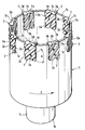
- This drawing shows a hollow drilling tool according to the invention in a perspective view.
- the hollow drilling tool essentially consists of a carrier body 1 with a front end 1a in the feed direction and a rear end 1b.
- the rear end 1b is designed as a reduced diameter connecting piece 1c for connection to a drilling device known per se, not shown.
- the end region adjoining the front end 1a is formed with essentially U-shaped recesses 1d for receiving cutting segments 2.
- the cutting segments 2 have an outwardly directed outer side 2a and an inwardly directed inner side 2b arranged opposite this.
- the cutting segments are provided on their outer side 2a and on their inner side 2b with channels 2c, 2d which are inclined to the longitudinal axis of the carrier body 1 and open on both sides and towards the outer contour.
- the channels 2c, 2d are arranged parallel to each other on one side.
- the pitch angle A of the channels 2c, 2d is approximately 45 °.
- the direction of inclination of the channels 2c, 2d is opposite on the outside 2a and on the inside 2b.
- the channels 2c, 2d can also be arranged only in part of the cutting segments 2 or on one side of the cutting segments 2. In the latter case, it is expedient to arrange the channels 2c on the outside 2a of the cutting segments 2.
Landscapes
- Engineering & Computer Science (AREA)
- Mining & Mineral Resources (AREA)
- Geology (AREA)
- Life Sciences & Earth Sciences (AREA)
- Mechanical Engineering (AREA)
- Environmental & Geological Engineering (AREA)
- Fluid Mechanics (AREA)
- Physics & Mathematics (AREA)
- General Life Sciences & Earth Sciences (AREA)
- Geochemistry & Mineralogy (AREA)
- Earth Drilling (AREA)
- Processing Of Stones Or Stones Resemblance Materials (AREA)
- Drilling Tools (AREA)
- Surgical Instruments (AREA)
- Dowels (AREA)
Description
- Die Erfindung betrifft ein Hohlbohrwerkzeug mit einem rohrförmigen Trägerkörper und an dessen in Vorschubrichtung vorderem Ende angeordneten, die Aussen- und die Innenkontur des Trägerkörpers überragenden Schneidsegmenten.
- Hohlbohrwerkzeuge der genannten, beispielsweise aus dem DE-GM 8 515 322 bekannten Art werden insbesondere zum Bohren von Löchern mit grossem querschnitt in Gestein, Beton, Mauerwerk und dergleichen verwendet. Die Schneidsegmente sind dabei mit abrasiven Schneidpartikeln, insbesondere mit synthetischen Diamanten versehen.
- Das Bohren erfolgt meist unter gleichzeitigem Zuführen einer Kühlflüssigkeit. Die Zufuhr der Kühlflüssigkeit erfolgt dabei mit mehr oder weniger hohem Druck und meist an der Innenseite des rohrförmigen Trägerkörpers entlang, so dass ein Abfliessen an der Aussenseite mitsamt dem Bohrgut gewährleistet ist. Allerdings ist es in der Praxis, insbesondere bei mobilen Bohrgeräten, nicht immer möglich, für die Kühlflüssigkeit einen ausreichend hohen Druck für die genügende Abfuhr des Bohrgutes zur Verfügung zu stellen.
- Der Erfindung liegt die Aufgabe zugrunde, ein Hohlbohrwerkzeug zu schaffen, das eine gute Abfuhr des Bohrgutes, auch bei geringerem apparativen Aufwand ermöglicht.
- Gemäss Erfindung wird dies dadurch erreicht, dass die Schneidsegmente an ihrer die Aussen- und die Innenkontur des Trägerkörpers überragenden Seiten mit mehreren innerhalb der Seiten parallel zueinander und zur Längsachse des Trägerkörpers in Bezug auf die Seiten gegensinnig geneigt verlaufenden, der Bohrgutabfuhr dienenden Kanäle versehen sind, wobei die Kanäle zu den Seiten und zu der diese Seiten begrenzenden Umfangskontur hin offen sind.
- Durch die Anordnung der Kanäle an der die Aussenkontur des Trägerkörpers überragenden Seite der Schneidsegmente wird die Kühlflüssigkeit samt dem Bohrgut zur Bohrlochmündung gefördert. Ein solch vorteilhaftes fördern wird insbesondere dann erzielt, wenn die Drehrichtung des Bohrwerkzeuges dem Steigungssinn der Kanäle entspricht.
- Durch die Anordnung von Kanälen der nach innen gerichteten Seite der Schneidsegmente wird die Kühlflüssigkeit zusätzlich an der Innenseite gegen den Bohrlochgrund gefördert. Die Steigung der Nuten an der Innenseite der Schneidsegmente verläuft gegensinnig zu den Nuten auf der Aussenseite der Segmente. Dadurch entsteht an der Innenseite der Schneidsegmente eine Förderung der Kühlflüssigkeit zum Bohrlochtiefsten hin und an der Aussenseite der Schneidsegmente eine Förderung in Richtung der Bohrlochmündung.
- Da die Schneidsegmente beim Einsatz des Hohlbohrwerkzeuges abgenutzt werden, ist durch die Anordnung mehrerer parallel zueinander verlaufender Kanäle während der ganzen Lebensdauer des Bohrwerkzeuges gewährleistet, dass Kanäle zur Abfuhr des Bohrgutes an den Schneidsegmenten zur Verfügung stehen.
- Eine gute Förderung des Bohrgutes wird mit zweckmässigerweise unter einem Steigungswinkel von 30° bis 60° verlaufenden Kanälen erzielt.
- Die Kanäle weisen vorteilhaft U-förmigen querschnitt auf. Der U-förmige querschnitt der Kanäle kann dabei eckig oder gerundet ausgebildet sein. Die Tiefe und Breite des U-förmigen Querschnitts der Kanäle entspricht vorzugsweise etwa dem Mass, um das die Schneidsegmente die Aussenkontur des Trägerkörpers überragen.
- Ein weiterer Vorteil der erfindungsgemässen Kanäle besteht darin, dass dadurch die Oberfläche der Schneidsegmente vergrössert und somit die Wärmeübertragung von den Schneidsegmenten an die Kühlflüssigkeit verbessert wird. Durch die verbesserte Wärmezufuhr können Ueberhitzungen der Schneidsegmente vermieden werden.
- Die Erfindung soll nachstehend anhand der sie beispielsweise wiedergebenden Zeichnung näher erläutert werden. Diese Zeichnung zeigt ein erfindungsgemässes Hohlbohrwerkzeug in perspektivischer Darstellung.
- Das Hohlbohrwerkzeug besteht im wesentlichen aus einem Trägerkörper 1 mit einem in Vorschubrichtung vorderen Ende 1a und einem rückwärtigen Ende 1b. Das rückwärtige Ende 1b ist als im Durchmesser reduzierter Anschlussstutzen 1c zum Verbinden mit einem an sich bekannten, nicht dargestellten Bohrgerät ausgebildet. Der an das vordere Ende 1a anschliessende Endbereich ist mit im wesentlichen U-förmigen Ausnehmungen 1d zur Aufnahme von Schneidsegmenten 2 ausgebildet. Die Schneidsegmente 2 weisen eine nach aussen gerichtete Aussenseite 2a und eine dieser gegenüberliegend angeordnete, nach innen gerichtete Innenseite 2b auf. Die Schneidsegmente sind an ihrer Aussenseite 2a und an ihrer Innenseite 2b mit zur Längsachse des Trägerkörpers 1 geneigt verlaufenden, beidseits und zur Aussenkontur hin offenen Kanälen 2c, 2d versehen. Die Kanäle 2c, 2d sind auf je einer Seite parallel zueinander angeordnet. Der Steigungswinkel A der Kanäle 2c, 2d beträgt etwa 45°. Der Steigungssinn der Kanäle 2c, 2d ist an der Aussenseite 2a und an der Innenseite 2b entgegengesetzt. Dadurch wird beim drehenden Antreiben des Hohlbohrwerkzeuges in Richtung des Pfeiles D durch die Kanäle 2d an der Innenseite 2b der Schneidsegmente eine zum vorderen Ende 1a des Trägerkörpers 1 bzw zum Bohrlochtiefsten hin wirkende Förderung eines flüssigen oder pastösen Kühl- bzw Schmiermittels erzeugt. Die an der Aussenseite 2a angeordneten Kanäle 2c bewirken dann eine Förderung des Kühlmittels samt dem anfallenden Bohrgut zum rückwärtigen Ende 1b des Trägerkörpers 1 bzw zur Bohrlochmündung hin.
- Die Kanäle 2c, 2d können auch nur bei einem Teil der Schneidsegmente 2 bzw auf einer Seite der Schneidsegmente 2 angeordnet werden. Im letzteren Fall ist es zweckmässig, die Kanäle 2c auf der Aussenseite 2a der Schneidsegmente 2 anzuordnen.
Claims (3)
dadurch gekennzeichnet, dass die Schneidsegmente (2) an ihrer die Aussen- und die Innenkontur des Trägerkörpers (1) überragenden Seiten (2a, 2b) mit mehreren, innerhalb der Seiten (2a, 2b) parallel zueinander und zur Längsachse des Trägerkörpers (1) in Bezug auf die Seiten (2a, 2b) gegensinnig geneigt verlaufenden, der Bohrgutabfuhr dienenden Kanälen (2c, 2d) versehen sind, wobei die Kanäle (2c, 2d) zu beiden Seiten (2a, 2b) und zu der diese Seiten (2a, 2b) begrenzenden Umfangskontur hin offen sind.
Priority Applications (1)
| Application Number | Priority Date | Filing Date | Title |
|---|---|---|---|
| AT89111381T ATE76480T1 (de) | 1988-07-01 | 1989-06-22 | Hohlbohrwerkzeug. |
Applications Claiming Priority (2)
| Application Number | Priority Date | Filing Date | Title |
|---|---|---|---|
| DE3822249A DE3822249A1 (de) | 1988-07-01 | 1988-07-01 | Hohlbohrwerkzeug |
| DE3822249 | 1988-07-01 |
Publications (2)
| Publication Number | Publication Date |
|---|---|
| EP0349846A1 EP0349846A1 (de) | 1990-01-10 |
| EP0349846B1 true EP0349846B1 (de) | 1992-05-20 |
Family
ID=6357726
Family Applications (1)
| Application Number | Title | Priority Date | Filing Date |
|---|---|---|---|
| EP89111381A Expired - Lifetime EP0349846B1 (de) | 1988-07-01 | 1989-06-22 | Hohlbohrwerkzeug |
Country Status (5)
| Country | Link |
|---|---|
| US (1) | US4915182A (de) |
| EP (1) | EP0349846B1 (de) |
| AT (1) | ATE76480T1 (de) |
| CA (1) | CA1314282C (de) |
| DE (2) | DE3822249A1 (de) |
Families Citing this family (20)
| Publication number | Priority date | Publication date | Assignee | Title |
|---|---|---|---|---|
| US5791837A (en) * | 1996-08-16 | 1998-08-11 | Johnson; Samuel | Annular tool for cutting holes in metal |
| US5868125A (en) * | 1996-11-21 | 1999-02-09 | Norton Company | Crenelated abrasive tool |
| US6250403B1 (en) * | 1997-09-30 | 2001-06-26 | The Charles Machine Works, Inc. | Device and method for enlarging a Bore |
| FR2824008A1 (fr) * | 2001-04-26 | 2002-10-31 | Michelin Soc Tech | Outil d'usinage de pneumatiques |
| US6761514B2 (en) | 2001-10-19 | 2004-07-13 | Master Tool Corporation | Hollow mill tool |
| US7373994B2 (en) * | 2004-10-07 | 2008-05-20 | Baker Hughes Incorporated | Self cleaning coring bit |
| RU2443847C1 (ru) * | 2010-10-11 | 2012-02-27 | Николай Митрофанович Панин | Буровая коронка |
| RU2460613C1 (ru) * | 2011-06-28 | 2012-09-10 | Юрий Михайлович Ермаков | Кольцевое сверло |
| RU2473772C1 (ru) * | 2011-10-27 | 2013-01-27 | Николай Митрофанович Панин | Коронка для ударно-вращательного бурения |
| US20130183891A1 (en) * | 2011-12-30 | 2013-07-18 | Ignazio Gosamo | Grinding Ring with Dual Function Grinding Segments |
| CA2825729C (en) * | 2012-11-21 | 2018-05-22 | Diamond Products, Limited | Diamond mining core drill bit and methods of making thereof |
| CN103195372B (zh) * | 2013-04-24 | 2016-08-17 | 中国电建集团中南勘测设计研究院有限公司 | 一种螺旋式钻头及一种泡沫钻进装置和泡沫钻进工艺 |
| KR101705194B1 (ko) * | 2015-07-06 | 2017-02-09 | 주식회사 에지텍 | 코어드릴 제조방법 및 상기 방법으로 제조되는 코어드릴 |
| BE1023352B1 (fr) * | 2016-01-29 | 2017-02-13 | Diarotech S.A. | Couronne miniere comprenant des segments impregnes de diamant obtenus par frittage a chaud |
| RU174005U1 (ru) * | 2016-02-16 | 2017-09-25 | Федеральное государственное бюджетное образовательное учреждение высшего образования Балтийский государственный технический университет "ВОЕНМЕХ" им. Д.Ф. Устинова (БГТУ "ВОЕНМЕХ") | Инструмент для сверления глубоких отверстий |
| USD951313S1 (en) | 2018-07-12 | 2022-05-10 | Halliburton Energy Services, Inc. | PDC cutter |
| US11105158B2 (en) | 2018-07-12 | 2021-08-31 | Halliburton Energy Services, Inc. | Drill bit and method using cutter with shaped channels |
| WO2021006912A1 (en) * | 2019-07-11 | 2021-01-14 | Halliburton Energy Services, Inc. | Drill bit cutter |
| KR102719479B1 (ko) * | 2024-01-09 | 2024-10-17 | 김영국 | 드릴 비트 및 상기 드릴 비트를 포함하는 저소음 착암기 |
| KR102730778B1 (ko) * | 2024-02-28 | 2024-11-14 | 김영국 | 암맥 절단형 무진동 할암 작업 공법 및 상기 암맥 절단형 무진동 할암 작업 공법에 적용되는 암맥 절단형 무진동 할암 작업용 저소음 착암기 |
Family Cites Families (16)
| Publication number | Priority date | Publication date | Assignee | Title |
|---|---|---|---|---|
| USRE23539E (en) * | 1952-08-26 | Drill bit | ||
| US817296A (en) * | 1905-03-31 | 1906-04-10 | William Besson | Tubular rock-boring drill. |
| US1172139A (en) * | 1913-10-02 | 1916-02-15 | William j mitchell | Swelled coupling and bit used in diamond-drilling. |
| US1168226A (en) * | 1914-06-18 | 1916-01-11 | Ed Rand | Well-drilling apparatus. |
| US1846177A (en) * | 1928-07-16 | 1932-02-23 | Calvin P Bascom | Coal drill |
| US2520876A (en) * | 1949-05-13 | 1950-08-29 | Koebel Diamond Tool Company | Core bit |
| US2838286A (en) * | 1956-04-19 | 1958-06-10 | Christensen Diamond Prod Co | Rotary drill bit |
| DE1083763B (de) * | 1958-08-22 | 1960-06-23 | Salzgitter Maschinen Ag | Vollbohrkrone |
| US3153885A (en) * | 1961-10-09 | 1964-10-27 | Chauncey A R Keller | Cyclindrical cutter device |
| US3217816A (en) * | 1964-12-10 | 1965-11-16 | Louis B Boyer | Method of removing pipe |
| US3692127A (en) * | 1971-05-10 | 1972-09-19 | Walter R Hampe | Rotary diamond core bit |
| DE2214021C2 (de) * | 1972-03-23 | 1973-09-20 | Ellmer, Kurt, 8580 Bayreuth | Werkzeuge zum Ausbohren von Erd kernen |
| AT373196B (de) * | 1980-11-11 | 1983-12-27 | Swarovski Tyrolit Schleif | Hohlbohrer |
| US4352400A (en) * | 1980-12-01 | 1982-10-05 | Christensen, Inc. | Drill bit |
| DE3566566D1 (en) * | 1984-10-11 | 1989-01-05 | Diamant Boart Sa | Stabilizer |
| DE3600189A1 (de) * | 1986-01-16 | 1987-07-16 | Kazachskij Politekhn I Im W I | Diamantbohrkrone |
-
1988
- 1988-07-01 DE DE3822249A patent/DE3822249A1/de not_active Withdrawn
-
1989
- 1989-06-22 AT AT89111381T patent/ATE76480T1/de not_active IP Right Cessation
- 1989-06-22 DE DE8989111381T patent/DE58901461D1/de not_active Expired - Fee Related
- 1989-06-22 EP EP89111381A patent/EP0349846B1/de not_active Expired - Lifetime
- 1989-06-30 CA CA000604551A patent/CA1314282C/en not_active Expired - Fee Related
- 1989-06-30 US US07/374,362 patent/US4915182A/en not_active Expired - Fee Related
Also Published As
| Publication number | Publication date |
|---|---|
| CA1314282C (en) | 1993-03-09 |
| ATE76480T1 (de) | 1992-06-15 |
| DE58901461D1 (de) | 1992-06-25 |
| DE3822249A1 (de) | 1990-01-04 |
| US4915182A (en) | 1990-04-10 |
| EP0349846A1 (de) | 1990-01-10 |
Similar Documents
| Publication | Publication Date | Title |
|---|---|---|
| EP0349846B1 (de) | Hohlbohrwerkzeug | |
| DE3587156T2 (de) | Drehbohrmeissel. | |
| DE60100727T2 (de) | Mehrrichtungsschneidelemente für bi-zentrales Bohrwerkzeug zum Bohren eines Verrohrungsschuhs | |
| EP0157395A2 (de) | Wirbelstrahldüse als hydraulisches Arbeitswerkzeug | |
| CH678834A5 (de) | ||
| DE19810192A1 (de) | Bohrwerkzeug | |
| EP0044386A1 (de) | Bohrvorrichtung zur Herstellung von Bohrlöchern mit Hinterschneidung | |
| DE60216793T2 (de) | Flüssigkeitsdichtung für nassankerbohrer | |
| EP0351699A2 (de) | Hohlbohrwerkzeug | |
| DE1812669A1 (de) | Kernbohrer | |
| DE19810193A1 (de) | Bohrwerkzeug | |
| EP0937860A1 (de) | Bohr- und/oder Meisselwerkzeug | |
| DE1483857A1 (de) | Rollenbohrer | |
| DE8121883U1 (de) | Vorrichtung für die Kühlmittelzufuhr zu mit Kühlmittelkanälen versehenen, rotierenden Schneidwerkzeugen für die spanende Metallbearbeitung, insbesondere Bohrwerkzeugen | |
| DE7806211U1 (de) | Bohrwerkzeug fuer bohrungen in metallvollmaterial von werkstuecken | |
| EP1083295A1 (de) | Bohrwerkzeug | |
| DE3731630A1 (de) | Bohrwerkzeug | |
| EP0138820A1 (de) | Vorrichtung zum einbringen von bohrlöchern in die seitenwände von unterirdischen abbauräumen geringer breite. | |
| DE2420442A1 (de) | Bohrkrone | |
| DE1980712U (de) | Vorrichtung zum bohren von loechern in einem von erdreich oder lockerem gestein bedeckten gebirge. | |
| CH696928A5 (de) | Kernbohrkrone, insbesondere Diamantbohrkrone, mit verbesserter Spülung. | |
| DE102014111500A1 (de) | Kernbohrwerkzeug und Verfahren zum Gesteinsbohren | |
| DE4204428C2 (de) | Hohlbohrwerkzeug zur Herstellung von zylindrischen Bohrungen | |
| DE2423510A1 (de) | Gesteinsbohrer | |
| DE3314422A1 (de) | Schlagbohrwerkzeug-kombination |
Legal Events
| Date | Code | Title | Description |
|---|---|---|---|
| PUAI | Public reference made under article 153(3) epc to a published international application that has entered the european phase |
Free format text: ORIGINAL CODE: 0009012 |
|
| AK | Designated contracting states |
Kind code of ref document: A1 Designated state(s): AT BE CH DE FR GB IT LI NL SE |
|
| 17P | Request for examination filed |
Effective date: 19900126 |
|
| 17Q | First examination report despatched |
Effective date: 19910513 |
|
| GRAA | (expected) grant |
Free format text: ORIGINAL CODE: 0009210 |
|
| ITF | It: translation for a ep patent filed | ||
| AK | Designated contracting states |
Kind code of ref document: B1 Designated state(s): AT BE CH DE FR GB IT LI NL SE |
|
| REF | Corresponds to: |
Ref document number: 76480 Country of ref document: AT Date of ref document: 19920615 Kind code of ref document: T |
|
| REF | Corresponds to: |
Ref document number: 58901461 Country of ref document: DE Date of ref document: 19920625 |
|
| ET | Fr: translation filed | ||
| GBT | Gb: translation of ep patent filed (gb section 77(6)(a)/1977) | ||
| PLBE | No opposition filed within time limit |
Free format text: ORIGINAL CODE: 0009261 |
|
| STAA | Information on the status of an ep patent application or granted ep patent |
Free format text: STATUS: NO OPPOSITION FILED WITHIN TIME LIMIT |
|
| 26N | No opposition filed | ||
| EAL | Se: european patent in force in sweden |
Ref document number: 89111381.3 |
|
| PGFP | Annual fee paid to national office [announced via postgrant information from national office to epo] |
Ref country code: NL Payment date: 19960630 Year of fee payment: 8 |
|
| PGFP | Annual fee paid to national office [announced via postgrant information from national office to epo] |
Ref country code: SE Payment date: 19970326 Year of fee payment: 9 |
|
| PGFP | Annual fee paid to national office [announced via postgrant information from national office to epo] |
Ref country code: GB Payment date: 19970612 Year of fee payment: 9 |
|
| PG25 | Lapsed in a contracting state [announced via postgrant information from national office to epo] |
Ref country code: NL Effective date: 19980101 |
|
| NLV4 | Nl: lapsed or anulled due to non-payment of the annual fee |
Effective date: 19980101 |
|
| PGFP | Annual fee paid to national office [announced via postgrant information from national office to epo] |
Ref country code: FR Payment date: 19980415 Year of fee payment: 10 |
|
| PG25 | Lapsed in a contracting state [announced via postgrant information from national office to epo] |
Ref country code: GB Free format text: LAPSE BECAUSE OF NON-PAYMENT OF DUE FEES Effective date: 19980622 |
|
| PG25 | Lapsed in a contracting state [announced via postgrant information from national office to epo] |
Ref country code: SE Free format text: LAPSE BECAUSE OF NON-PAYMENT OF DUE FEES Effective date: 19980623 |
|
| GBPC | Gb: european patent ceased through non-payment of renewal fee |
Effective date: 19980622 |
|
| EUG | Se: european patent has lapsed |
Ref document number: 89111381.3 |
|
| PG25 | Lapsed in a contracting state [announced via postgrant information from national office to epo] |
Ref country code: FR Free format text: THE PATENT HAS BEEN ANNULLED BY A DECISION OF A NATIONAL AUTHORITY Effective date: 19990630 |
|
| REG | Reference to a national code |
Ref country code: FR Ref legal event code: ST |
|
| PGFP | Annual fee paid to national office [announced via postgrant information from national office to epo] |
Ref country code: BE Payment date: 20000818 Year of fee payment: 12 |
|
| PG25 | Lapsed in a contracting state [announced via postgrant information from national office to epo] |
Ref country code: BE Free format text: LAPSE BECAUSE OF NON-PAYMENT OF DUE FEES Effective date: 20010630 |
|
| BERE | Be: lapsed |
Owner name: HILTI A.G. Effective date: 20010630 |
|
| PGFP | Annual fee paid to national office [announced via postgrant information from national office to epo] |
Ref country code: DE Payment date: 20040527 Year of fee payment: 16 |
|
| PGFP | Annual fee paid to national office [announced via postgrant information from national office to epo] |
Ref country code: AT Payment date: 20040611 Year of fee payment: 16 |
|
| PGFP | Annual fee paid to national office [announced via postgrant information from national office to epo] |
Ref country code: CH Payment date: 20040629 Year of fee payment: 16 |
|
| PG25 | Lapsed in a contracting state [announced via postgrant information from national office to epo] |
Ref country code: IT Free format text: LAPSE BECAUSE OF NON-PAYMENT OF DUE FEES;WARNING: LAPSES OF ITALIAN PATENTS WITH EFFECTIVE DATE BEFORE 2007 MAY HAVE OCCURRED AT ANY TIME BEFORE 2007. THE CORRECT EFFECTIVE DATE MAY BE DIFFERENT FROM THE ONE RECORDED. Effective date: 20050622 Ref country code: AT Free format text: LAPSE BECAUSE OF NON-PAYMENT OF DUE FEES Effective date: 20050622 |
|
| PG25 | Lapsed in a contracting state [announced via postgrant information from national office to epo] |
Ref country code: LI Free format text: LAPSE BECAUSE OF NON-PAYMENT OF DUE FEES Effective date: 20050630 Ref country code: CH Free format text: LAPSE BECAUSE OF NON-PAYMENT OF DUE FEES Effective date: 20050630 |
|
| PG25 | Lapsed in a contracting state [announced via postgrant information from national office to epo] |
Ref country code: DE Free format text: LAPSE BECAUSE OF NON-PAYMENT OF DUE FEES Effective date: 20060103 |
|
| REG | Reference to a national code |
Ref country code: CH Ref legal event code: PL |