EP0349347A1 - Optical marking system having marking mode selecting function - Google Patents
Optical marking system having marking mode selecting function Download PDFInfo
- Publication number
- EP0349347A1 EP0349347A1 EP89306691A EP89306691A EP0349347A1 EP 0349347 A1 EP0349347 A1 EP 0349347A1 EP 89306691 A EP89306691 A EP 89306691A EP 89306691 A EP89306691 A EP 89306691A EP 0349347 A1 EP0349347 A1 EP 0349347A1
- Authority
- EP
- European Patent Office
- Prior art keywords
- optical
- pattern
- light beam
- marking apparatus
- forming
- Prior art date
- Legal status (The legal status is an assumption and is not a legal conclusion. Google has not performed a legal analysis and makes no representation as to the accuracy of the status listed.)
- Granted
Links
- 230000003287 optical effect Effects 0.000 title claims abstract description 97
- 230000000694 effects Effects 0.000 claims abstract description 6
- 238000000034 method Methods 0.000 claims description 22
- 238000005530 etching Methods 0.000 claims description 2
- 230000005540 biological transmission Effects 0.000 description 27
- 238000010586 diagram Methods 0.000 description 10
- 238000010276 construction Methods 0.000 description 6
- 238000010330 laser marking Methods 0.000 description 4
- 230000002950 deficient Effects 0.000 description 1
- 230000002708 enhancing effect Effects 0.000 description 1
- 238000004519 manufacturing process Methods 0.000 description 1
Images


Classifications
-
- B—PERFORMING OPERATIONS; TRANSPORTING
- B23—MACHINE TOOLS; METAL-WORKING NOT OTHERWISE PROVIDED FOR
- B23K—SOLDERING OR UNSOLDERING; WELDING; CLADDING OR PLATING BY SOLDERING OR WELDING; CUTTING BY APPLYING HEAT LOCALLY, e.g. FLAME CUTTING; WORKING BY LASER BEAM
- B23K26/00—Working by laser beam, e.g. welding, cutting or boring
- B23K26/352—Working by laser beam, e.g. welding, cutting or boring for surface treatment
- B23K26/359—Working by laser beam, e.g. welding, cutting or boring for surface treatment by providing a line or line pattern, e.g. a dotted break initiation line
-
- G—PHYSICS
- G06—COMPUTING; CALCULATING OR COUNTING
- G06K—GRAPHICAL DATA READING; PRESENTATION OF DATA; RECORD CARRIERS; HANDLING RECORD CARRIERS
- G06K15/00—Arrangements for producing a permanent visual presentation of the output data, e.g. computer output printers
- G06K15/02—Arrangements for producing a permanent visual presentation of the output data, e.g. computer output printers using printers
- G06K15/12—Arrangements for producing a permanent visual presentation of the output data, e.g. computer output printers using printers by photographic printing, e.g. by laser printers
- G06K15/1238—Arrangements for producing a permanent visual presentation of the output data, e.g. computer output printers using printers by photographic printing, e.g. by laser printers simultaneously exposing more than one point
-
- B—PERFORMING OPERATIONS; TRANSPORTING
- B23—MACHINE TOOLS; METAL-WORKING NOT OTHERWISE PROVIDED FOR
- B23K—SOLDERING OR UNSOLDERING; WELDING; CLADDING OR PLATING BY SOLDERING OR WELDING; CUTTING BY APPLYING HEAT LOCALLY, e.g. FLAME CUTTING; WORKING BY LASER BEAM
- B23K26/00—Working by laser beam, e.g. welding, cutting or boring
- B23K26/02—Positioning or observing the workpiece, e.g. with respect to the point of impact; Aligning, aiming or focusing the laser beam
- B23K26/06—Shaping the laser beam, e.g. by masks or multi-focusing
- B23K26/064—Shaping the laser beam, e.g. by masks or multi-focusing by means of optical elements, e.g. lenses, mirrors or prisms
- B23K26/066—Shaping the laser beam, e.g. by masks or multi-focusing by means of optical elements, e.g. lenses, mirrors or prisms by using masks
-
- G—PHYSICS
- G06—COMPUTING; CALCULATING OR COUNTING
- G06K—GRAPHICAL DATA READING; PRESENTATION OF DATA; RECORD CARRIERS; HANDLING RECORD CARRIERS
- G06K1/00—Methods or arrangements for marking the record carrier in digital fashion
- G06K1/12—Methods or arrangements for marking the record carrier in digital fashion otherwise than by punching
- G06K1/126—Methods or arrangements for marking the record carrier in digital fashion otherwise than by punching by photographic or thermographic registration
-
- G—PHYSICS
- G06—COMPUTING; CALCULATING OR COUNTING
- G06K—GRAPHICAL DATA READING; PRESENTATION OF DATA; RECORD CARRIERS; HANDLING RECORD CARRIERS
- G06K15/00—Arrangements for producing a permanent visual presentation of the output data, e.g. computer output printers
- G06K15/02—Arrangements for producing a permanent visual presentation of the output data, e.g. computer output printers using printers
- G06K15/12—Arrangements for producing a permanent visual presentation of the output data, e.g. computer output printers using printers by photographic printing, e.g. by laser printers
- G06K15/1228—Arrangements for producing a permanent visual presentation of the output data, e.g. computer output printers using printers by photographic printing, e.g. by laser printers involving the fast moving of a light beam in two directions
Definitions
- This invention relates to a marking apparatus and a marking method; more particularly, to an optical marking apparatus and a method for applying a light beam to an object, to form a mark thereon.
- Laser marking is essentially a technique of marking on a given product the name of the manufacturer and a serial number, by means of a laser beam, so as to render the product readily identifiable.
- One method used in the case of relatively complicated patterns, such as a company emblem or Chinese characters, is to raster-scan the mask of a pattern to be formed on an object or work by means of a laser beam, and then to project a light beam having a cross section corresponding to the pattern onto the object surface.
- the other method used in the case of simple designs, such as serial numbers, is to scan a laser beam in a single stroke, without using a mask, and thus directly mark the object.
- a desired pattern can be formed in advance on a mask by, for example, etching and thus a relatively complicated pattern can be marked easily and precisely.
- this method has a problem in that it requires changing masks every time a new pattern is intended to be marked. This renders the operation of the system undesirably complicated.
- a pattern can be marked by the laser beam being moved by CPU control in accordance with the pattern to be formed.
- the more complicated the pattern to be formed the more complicated the movement of the light beam is likely to be, thus necessitating ever more complex programming for controlling the movement of the light beam.
- employing the direct beam application method has a limitation in that the shape of a pattern marked is defined by the spot shape of the laser beam as well as the spot diameter. In other words, if a laser beam having a large spot is used, the edge portion of the pattern marked may be rounded rather than sharply defined.
- An object of this invention is to provide an optical marking apparatus capable of precisely marking on an object a combination of a complicated pattern and a simple pattern by means of selective setting of the marking mode.
- Another object of this invention is to provide a marking method for precise marking of a combination of a complicated pattern and a simple pattern by means of selective setting of the marking mode.
- Yet another object of this invention is to provide an optical marking apparatus capable of producing sharply defined marking patterns with high efficiency.
- a further object of this invention is to provide an optical marking method for producing sharply defined marking patterns with high efficiency.
- an optical marking apparatus comprising a light source for generating a light beam of a predetermined wavelength, optical means for receiving the light beam gnerated by the light source and directing the received light beam in a present direction, forming means positioned in connection with the optical means, and including a pattern forming section and a non-pattern forming section, and control means connectd to the optical means, for controlling the optical means to effect a first mode, in which the light beam is directed to the pattern forming section of the forming means, to form a predetermined pattern, and a second mode, in which the light beam is directed to the non-pattern forming section of the forming means, the first and second modes being effected in a present sequence.
- an optical marking method comprising the steps of generating a light beam of a preset wavelength, controlling an optical system to generate a preset pattern by directing the light beam to a pattern generator, in a first mode, and controlling the optical system in a second mode to directly apply the light beam to an object.
- the optical marking system includes light source 11 for generating a light beam of a predetermined wavelength, optical system 60 for receiving the light beam generated by light source 11 and directing the received light beam in a preset direction, pattern generator 18 positioned in connection with optical system 60, and including a pattern forming section and a non-pattern forming section, and control section 50 connected to optical system 60, for controlling optical system 60 to effect a first mode in which the light beam is directed to the pattern forming section of pattern generator 18, to form a predetermined pattern, and a second mode, in which the light beam is directed to the non-pattern forming section of pattern generator 18, the first and second modes being effected in a preset sequence.
- the optical marking system of this invention includes light source 121 for generating a light beam of a predetermined wavelength suitable for optically marking a work, first optical system 123 for receiving the light beam generated by light source 121 and directing the received light beam in a preset direction, pattern generator 29 positioned in connection with first optical system 123, and including a plurality of patterns of at least one kind and of different sizes, first control section 50a, connected to first optical system 123, for controlling first optical system 123 to select one of the plurality of patterns of pattern generator 29, second optical system 33, for receiving a light pattern corresponding to the pattern selected by means of first control section 50a and directing the light pattern to the work, and second control section 50b, connected to second optical system 33, for controlling second optical system 33 to mark the work according to the pattern selected by means of first control section 50a.
- Fig. 1 is a diagram showing the optical marking system according to the first embodiment of this invention.
- the optical marking system includes laser oscillator 11 for generating a laser beam of a preset wavelength.
- Laser oscillator 11 uses a laser that generates a Q switching output of peak power.
- Laser beam L generated by laser oscillator 11 is passed through condenser lens 12 and directed to first mirror 13.
- First mirror 13 is driven to rotatively oscillate in a preset angle range by means of first galvanometer scanner 14.
- Laser beam L reflected by means of first mirror 13 is transmitted to second mirror 15.
- Second mirror 15 is driven to rotatively oscillate in a preset angle range by means of second galvanometer scanner 16.
- First and second galvanometer scanners 14 and 16 are arranged such that the rotation axes thereof are set perpendicular to each other. With this arrangement, incident laser beam L can be deflected in a direction of X axis by rotatively oscillating first mirror 13 by means of first galvanometer scanner 14, and at the same time, incident laser beam L can be deflected in a direction of Y axis by rotatively oscillating second mirror 15 by means of second galvanometer scanner 16.
- Laser beam L reflected by means of second mirror 15 is applied to object 21 via relay lens 17, rectangular mask 18 and image-forming lens 19.
- a complicated pattern for example, "T NO4"
- T NO4 a company emblem
- Relay lens 17 is formed sufficiently large so as to direct laser beam L to image-forming lens 19 after laser beam L reflected by second mirror 15 has passed through pattern section 22 or opening 23 of mask 18. This will be clearly understood from the fact that it is necessary to place relay lens 17 of at least the same size as mask 18 in front of mask 18 as shown in Fig. 4 in order to apply laser beam L to the entire portion of mask 18. Laser beam L directed to image-forming lens 19 via mask 18 by means of relay lens 17 is converged by means of image-forming lens 19 and then applied to object 21.
- the control circuit includes computer control section 50 which includes central processing unit (CPU) 52, memory (MEM) 53, digital-analog (D/A) converter 54, PIO 55 serving as an interface for the Q switching and bus 51 serving as a path for data transfer between the above circuits.
- CPU central processing unit
- MEM memory
- D/A digital-analog
- PIO 55 serving as an interface for the Q switching and bus 51 serving as a path for data transfer between the above circuits.
- one of the first mode (raster scan mode) and the second mode (character mode) described before is selected by reading out a preset program stored in memory 53. Then, CPU 52 supplies a preset digital signal corresponding to the selected mode to D/A converter 54 which in turn converts the input digital signal to an analog signal and supplies the analog signal to scanner drivers 58 and 59. Scanner drivers 58 and 59 respectively drive galvanometer scanners 14 and 16 so as to rotate first and second mirrors 13 and 15 by a preset angle. As a result, laser beam L generated by laser oscillator 11 is controlled so that laser beam L can be directed and applied to a desired portion of object 21. The adjustment of the marking position prior to the marking can be effected while observing the marking position displayed on display 56. Further, when the laser marking system becomes defective, the marking operation can be interrupted by supplying a preset signal from keyboard 57.
- step 1 a work position is determined and the workpiece to be marked is set by a positioning apparatus, such as a handler.
- step 2 data for the marking is input as codes into memory (MEM) 53.
- the codes represent characters to be formed or patterns such as trademarks, or the marking modes. For example, when the mark “T NO22" is intended to be formed on the workpiece, a code “R1” is used for forming "T NO” in the raster-scan mode, and two codes “C2C2" are used for forming the serial number "22" in the character mode. Therefore, the resulting codes for forming "T NO22" will be “R1C2C2".
- step 3 it is judged whether the raster-scan mode or character mode in set.
- the raster-scan mode is selected and executed in step 4.
- laser beam L generated by laser oscillator 11 is controlled by the rotation movement of first and second mirrors 13 and 15 so as to raster-scan the entire portion of pattern 22 (area a surrounded by chain lines) of mask 18.
- Laser beam L passes through only pattern 22 formed on mask 18 and is focused on object 21 by means of image-forming lens 19.
- mark m1 of "T NO" is formed on object 21.
- step 6 it is judged in step 6 whether the marking process is completed or not. In this case, "NO" is selected and step 3 is repeated.
- the character mode is selected this time and is excecuted in step 5.
- step 7 it is judged whether another workpiece is positioned. When it is detected that another workpiece is positioned, step 1 is executed again to repeatedly effect the same operation. When it is detected that no workpiece is positioned, the marking operation is interrupted.
- the marking operations for a complicated pattern which is seldom changed and a pattern which is frequently changed are separately effected in two different modes. Therefore, the operation of an optical marking system can be simplified.
- the galvanometer scanner is used as a device for rotating the mirror, but the device is not limited thereto and may be constituted by a motor, for example. Also, it is possible to use a polygon mirror as the mirror.
- the opening is formed in the mask in the above embodiment, but a light transmission body may be formed instead of forming the opening. Further, it is also possible to use a mask having only the unchanged portion without forming the opening.
- the optical marking system shown in Fig. 8 includes laser oscillator 121.
- Laser oscillator 121 generates laser beam L having a circular cross section which passes first lens 122 and enters optical system 123 for freely setting the travelling direction of laser beam L.
- Optical system 123 includes first mirror 25 which is rotatively oscillated by means of first galvanometer scanner 24 and second mirror 27 which is rotatively oscillated by means of second galvanometer scanner 26.
- First and second galvanometer scanners 24 and 26 are arranged such that the rotation axes 24a and 26a thereof are set perpendicular to each other.
- incident laser beam L can be deflected in an X direction by means of first mirror 25, and incident laser beam L can be deflected in a Y direction by means of second mirror 27. That is, laser beam L can be deflected in the X and Y directions by means of optical system 123.
- Pattern mask 29 has a plurality of rectangular light transmission patterns 31a, 31b, ... with different sizes and a plurality of circular light transmission patterns 32a, 32b, ... with different sizes formed as the transmission pattern through which laser beam L passes.
- laser beam L can pass a selected one of the light transmission patterns by changing the travelling direction of laser beam L by means of optical system 123.
- Scanning system 33 includes third mirror 35 which is rotatively oscillated by means of third galvanometer scanner 34 and fourth mirror 37 which is rotatively oscillated by means of fourth galvanometer scanner 36.
- First and second galvanometer scanners 34 and 36 are arranged such that the rotation axes 34a and 36a thereof are set perpendicular to each other.
- third mirror 35 is disposed in position so that laser beam L having passed the selected light transmission pattern can enter third mirror 35. Therefore, laser beam L incident on third mirror 35 may be deflected in the X direction and laser beam L incident on fourth mirror 37 may be deflected in the Y direction.
- Laser beam L from fourth mirror 37 of scanning system 33 is converged by means of second lens 38 and focused on work 39. That is, laser beam L applied to work 39 and having a cross section corresponding to a selected light transmission pattern of pattern mask 39 is scanned in the X and Y directions on work 39 by means of scanning system 33.
- first and second mirrors 25 and 27 in the X and Y directions are respectively set by means of first and second galvanometer scanners 24 and 26 so that laser beam L generated by laser oscillator 21 can pass rectangular light transmission pattern 31a having a dimension corresponding to the line width of mark "F".
- first and second mirrors 25 and 27 in the X and Y directions are set in this way, laser beam L is generated by laser oscillator 21 and at the same time laser beam L which has passed relay lens 28 and first light transmission pattern 31a is scanned by means of controlling the rotation movement of third and fourth mirrors 35 and 37 to draw mark "F" on work 39.
- mark "F” as shown in Fig. 9 can be formed on work 39.
- first rectangular light transmission pattern 31a of pattern mask 29 when laser beam L has passed first rectangular light transmission pattern 31a of pattern mask 29, laser spot Sl having a rectangular cross section corresponding to first rectangular light transmission pattern 31a is emitted from first rectangular light transmission pattern 31a.
- mark "F” can be formed on work 39 without rounding the edge portion thereof.
- laser beam L is directed to pass first rectangular light transmission pattern 31a which is one of a plurality of rectangular light transmission patterns 31a, 31b, 31c, ... and has a dimension corresponding to the line width of mark "F". Therefore, the entire portion of the line width of mark "F” can be made by directly using rectangular spot S1 emitted from first rectangular light transmission pattern 31a. In other words, it is not necessary to repeatedly scan spot S1 in order to mark the entire portion of the line width dark, and therefore the operational efficiency of the optical marking system can be improved.
- the laser marking for making a mark including a round edge portion that one of circular light transmission patterns 32a, 32b, 32c, ... whose dimension corresponds to the line width of the mark is selected and then laser beam L is controlled by means of scanning system 33 to pass the selected circular light transmission pattern and is scanned.
- Fig. 10 shows an optical marking system according to a third embodiment of this invention.
- third light transmission pattern 41 such as a company emblem or a mold number which is frequently used is formed on pattern mask 29A in addition to first rectangular light transmission patterns 31a, 31b, 31c, ... and second circular light transmission patterns 32a, 32b, 32c, ...
- second lens 28 is disposed on the incident side of third mirror 35 but can be disposed on the emission side of fourth mirror 37 in the same manner as in the second embodiment.
- pattern mask 29A of the above construction the mark such as the company emblem which is frequently used can be efficiently and stably made by scanning laser beam L on the entire portion of third light transmission pattern 41 as shown by arrow a.
- one of first light transmission patterns having a desired dimension is selected in the same manner as in the second embodiment and then laser beam L is passed through the selected first light transmission pattern and is scanned in a single stroke by means of third and fourth mirrors 35 and 37 so as to make a mark having sharp edge portions.
- a rectangular pattern is used as the first polygonal light transmission pattern, but another polygonal pattern such as a pentagonal or hexagonal pattern may be used depending on the shape of a mark to be made.
- a control circuit shown in Fig. 11 is used. As is clearly shown from Fig. 11, the control circuit is similar to that of the first embodiment except that two additional optical systems are used in the second and third embodiments.
- a plurality of polygonal patterns of different sizes are formed in the pattern mask. Therefore, after the laser beam has passed the light transmission pattern, the laser beam will have a cross section of a corresponding polygonal shape. As a result, the edge portion can be marked sharply.
- a desired mark can be made with one scanning operation by selecting a light transmission pattern of a dimension corresponding to the line width of the mark, thus enhancing the operational efficiency of optical marking system.
Landscapes
- Engineering & Computer Science (AREA)
- Physics & Mathematics (AREA)
- Optics & Photonics (AREA)
- General Physics & Mathematics (AREA)
- Theoretical Computer Science (AREA)
- Plasma & Fusion (AREA)
- Mechanical Engineering (AREA)
- General Engineering & Computer Science (AREA)
- Laser Beam Processing (AREA)
Abstract
Description
- This invention relates to a marking apparatus and a marking method; more particularly, to an optical marking apparatus and a method for applying a light beam to an object, to form a mark thereon.
- Laser marking is essentially a technique of marking on a given product the name of the manufacturer and a serial number, by means of a laser beam, so as to render the product readily identifiable.
- There are two main methods of forming marks by laser making. One method, used in the case of relatively complicated patterns, such as a company emblem or Chinese characters, is to raster-scan the mask of a pattern to be formed on an object or work by means of a laser beam, and then to project a light beam having a cross section corresponding to the pattern onto the object surface. The other method, used in the case of simple designs, such as serial numbers, is to scan a laser beam in a single stroke, without using a mask, and thus directly mark the object.
- In the case of the marking technique using a mask, a desired pattern can be formed in advance on a mask by, for example, etching and thus a relatively complicated pattern can be marked easily and precisely. However, in the case where simple designs are intended to be marked, this method has a problem in that it requires changing masks every time a new pattern is intended to be marked. This renders the operation of the system undesirably complicated.
- In the case of the technique of applying a laser beam directly to the object, a pattern can be marked by the laser beam being moved by CPU control in accordance with the pattern to be formed. However, the more complicated the pattern to be formed, the more complicated the movement of the light beam is likely to be, thus necessitating ever more complex programming for controlling the movement of the light beam.
- Moreover, employing the direct beam application method has a limitation in that the shape of a pattern marked is defined by the spot shape of the laser beam as well as the spot diameter. In other words, if a laser beam having a large spot is used, the edge portion of the pattern marked may be rounded rather than sharply defined.
- An object of this invention is to provide an optical marking apparatus capable of precisely marking on an object a combination of a complicated pattern and a simple pattern by means of selective setting of the marking mode.
- Another object of this invention is to provide a marking method for precise marking of a combination of a complicated pattern and a simple pattern by means of selective setting of the marking mode.
- Yet another object of this invention is to provide an optical marking apparatus capable of producing sharply defined marking patterns with high efficiency.
- A further object of this invention is to provide an optical marking method for producing sharply defined marking patterns with high efficiency.
- According to one aspect of this invention, there is provided an optical marking apparatus comprising a light source for generating a light beam of a predetermined wavelength, optical means for receiving the light beam gnerated by the light source and directing the received light beam in a present direction, forming means positioned in connection with the optical means, and including a pattern forming section and a non-pattern forming section, and control means connectd to the optical means, for controlling the optical means to effect a first mode, in which the light beam is directed to the pattern forming section of the forming means, to form a predetermined pattern, and a second mode, in which the light beam is directed to the non-pattern forming section of the forming means, the first and second modes being effected in a present sequence.
- According to the other aspect of this invention, there is provided an optical marking method comprising the steps of generating a light beam of a preset wavelength, controlling an optical system to generate a preset pattern by directing the light beam to a pattern generator, in a first mode, and controlling the optical system in a second mode to directly apply the light beam to an object.
- The foregoing aspects and other features of the invention will be explained in the following description in connection with the accompanying drawings, wherein:
- Fig. 1 is a diagram showing an optical marking system according to a first embodiment of this invention;
- Fig. 2 is a perspective view of a mask used in an optical marking system according to this invention;
- Fig. 3 is a perspective view of an object which has been subjected to the marking process;
- Fig. 4 is a diagram showing the dimensional relation between the mask and lenses;
- Fig. 5 is a block diagram of a control circuit for controlling the optical marking system of Fig. 1;
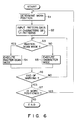
- Fig. 6 is a flowchart showing the sequence of operations for effecting two modes of the optical marking system of Fig. 1;
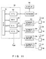
- Fig. 7 is a block diagram for illustrating the schematic construction of the optical marking system according to the first embodiment of this invention;
- Fig. 8 is a diagram showing an optical marking system according to a second embodiment of this invention;
- Fig. 9 shows a case where mark "F" is made;
- Fig. 10 is a diagram showing an optical marking system according to a third embodiment of this invention;
- Fig. 11 is a block diagram of a control circuit for controlling the optical marking system of Figs. 8 and 10; and
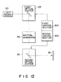
- Fig. 12 is a block diagram for illustrating the schematic construction of the optical marking system according to the second and third embodiments of this invention.
- First, the schematic construction of an optical marking system according to a first embodiment of this invention is explained with reference to Fig. 7.
- The optical marking system includes
light source 11 for generating a light beam of a predetermined wavelength,optical system 60 for receiving the light beam generated bylight source 11 and directing the received light beam in a preset direction,pattern generator 18 positioned in connection withoptical system 60, and including a pattern forming section and a non-pattern forming section, andcontrol section 50 connected tooptical system 60, for controllingoptical system 60 to effect a first mode in which the light beam is directed to the pattern forming section ofpattern generator 18, to form a predetermined pattern, and a second mode, in which the light beam is directed to the non-pattern forming section ofpattern generator 18, the first and second modes being effected in a preset sequence. - Further, the schematic construction of an optical marking system according to each of second and third embodiments of this invention is explained with reference to Fig. 12.
- The optical marking system of this invention includes
light source 121 for generating a light beam of a predetermined wavelength suitable for optically marking a work, firstoptical system 123 for receiving the light beam generated bylight source 121 and directing the received light beam in a preset direction,pattern generator 29 positioned in connection with firstoptical system 123, and including a plurality of patterns of at least one kind and of different sizes,first control section 50a, connected to firstoptical system 123, for controlling firstoptical system 123 to select one of the plurality of patterns ofpattern generator 29, secondoptical system 33, for receiving a light pattern corresponding to the pattern selected by means offirst control section 50a and directing the light pattern to the work, andsecond control section 50b, connected to secondoptical system 33, for controlling secondoptical system 33 to mark the work according to the pattern selected by means offirst control section 50a. - Now, the optical marking system according to the first embodiment of this invention is explained.
- Fig. 1 is a diagram showing the optical marking system according to the first embodiment of this invention. The optical marking system includes
laser oscillator 11 for generating a laser beam of a preset wavelength.Laser oscillator 11 uses a laser that generates a Q switching output of peak power. Laser beam L generated bylaser oscillator 11 is passed throughcondenser lens 12 and directed tofirst mirror 13.First mirror 13 is driven to rotatively oscillate in a preset angle range by means offirst galvanometer scanner 14. Laser beam L reflected by means offirst mirror 13 is transmitted tosecond mirror 15.Second mirror 15 is driven to rotatively oscillate in a preset angle range by means ofsecond galvanometer scanner 16. First andsecond galvanometer scanners first mirror 13 by means offirst galvanometer scanner 14, and at the same time, incident laser beam L can be deflected in a direction of Y axis by rotatively oscillatingsecond mirror 15 by means ofsecond galvanometer scanner 16. - Laser beam L reflected by means of
second mirror 15 is applied toobject 21 viarelay lens 17,rectangular mask 18 and image-forminglens 19. As shown in Fig. 2, a complicated pattern (for example, "T NO4") such as a company emblem is formed on the left portion ofmask 18 andrectangular opening 23 is formed in the right portion thereof. -
Relay lens 17 is formed sufficiently large so as to direct laser beam L to image-forminglens 19 after laser beam L reflected bysecond mirror 15 has passed throughpattern section 22 or opening 23 ofmask 18. This will be clearly understood from the fact that it is necessary to placerelay lens 17 of at least the same size asmask 18 in front ofmask 18 as shown in Fig. 4 in order to apply laser beam L to the entire portion ofmask 18. Laser beam L directed to image-forminglens 19 viamask 18 by means ofrelay lens 17 is converged by means of image-forminglens 19 and then applied toobject 21. - Now, the control circuit of the optical marking system according to the first embodiment of this invention is explained with reference to a block diagram of Fig. 5. The control circuit includes
computer control section 50 which includes central processing unit (CPU) 52, memory (MEM) 53, digital-analog (D/A)converter 54,PIO 55 serving as an interface for the Q switching andbus 51 serving as a path for data transfer between the above circuits. - For example, one of the first mode (raster scan mode) and the second mode (character mode) described before is selected by reading out a preset program stored in
memory 53. Then,CPU 52 supplies a preset digital signal corresponding to the selected mode to D/A converter 54 which in turn converts the input digital signal to an analog signal and supplies the analog signal to scannerdrivers Scanner drivers galvanometer scanners second mirrors laser oscillator 11 is controlled so that laser beam L can be directed and applied to a desired portion ofobject 21. The adjustment of the marking position prior to the marking can be effected while observing the marking position displayed ondisplay 56. Further, when the laser marking system becomes defective, the marking operation can be interrupted by supplying a preset signal fromkeyboard 57. - Now, the marking process for marking a combination of a complicated pattern made on the mask and a simple pattern which can be formed with a single stroke, for example, "T NO22" is explained with reference to the flowchart of Fig. 6. Mark "T NO" is an unchanged portion which is seldom changed for each marking process and the serial number "22" is frequently changed. As described before, in this invention, the raster-scan mode in which a pattern on the mask is formed and the character mode in which a pattern is formed with a single stroke are used.
- First, in
step 1, a work position is determined and the workpiece to be marked is set by a positioning apparatus, such as a handler. Instep 2, data for the marking is input as codes into memory (MEM) 53. The codes represent characters to be formed or patterns such as trademarks, or the marking modes. For example, when the mark "T NO22" is intended to be formed on the workpiece, a code "R1" is used for forming "T NO" in the raster-scan mode, and two codes "C2C2" are used for forming the serial number "22" in the character mode. Therefore, the resulting codes for forming "T NO22" will be "R1C2C2". Instep 3, it is judged whether the raster-scan mode or character mode in set. In this case, the raster-scan mode is selected and executed in step 4. When the raster-scan mode is effected, laser beam L generated bylaser oscillator 11 is controlled by the rotation movement of first andsecond mirrors mask 18. Laser beam L passes throughonly pattern 22 formed onmask 18 and is focused onobject 21 by means of image-forminglens 19. In this way, mark m1 of "T NO" is formed onobject 21. After this, it is judged in step 6 whether the marking process is completed or not. In this case, "NO" is selected andstep 3 is repeated. Instep 3, the character mode is selected this time and is excecuted instep 5. - When the character mode is effected, laser beam L generated by
laser oscillator 11 is controlled by the rotation movement of first andsecond mirrors mask 18 and draw the number "2" onobject 21. To complete the marking of "22", the character mode is repeated. In step 7, it is judged whether another workpiece is positioned. When it is detected that another workpiece is positioned,step 1 is executed again to repeatedly effect the same operation. When it is detected that no workpiece is positioned, the marking operation is interrupted. - In this way, a combination of mark m1 of "T NO" and mark m2 of serial number "22" can be formed on the workpiece, as shown in Fig. 3.
- As described above, in this invention, the marking operations for a complicated pattern which is seldom changed and a pattern which is frequently changed are separately effected in two different modes. Therefore, the operation of an optical marking system can be simplified.
- Further, in the embodiment of this invention, the galvanometer scanner is used as a device for rotating the mirror, but the device is not limited thereto and may be constituted by a motor, for example. Also, it is possible to use a polygon mirror as the mirror. The opening is formed in the mask in the above embodiment, but a light transmission body may be formed instead of forming the opening. Further, it is also possible to use a mask having only the unchanged portion without forming the opening.
- Now, an optical marking system according to the second embodiment of this invention is explained with reference to Fig. 8. The optical marking system shown in Fig. 8 includes
laser oscillator 121.Laser oscillator 121 generates laser beam L having a circular cross section which passesfirst lens 122 and entersoptical system 123 for freely setting the travelling direction of laser beamL. Optical system 123 includesfirst mirror 25 which is rotatively oscillated by means offirst galvanometer scanner 24 andsecond mirror 27 which is rotatively oscillated by means ofsecond galvanometer scanner 26. First andsecond galvanometer scanners first mirror 25, and incident laser beam L can be deflected in a Y direction by means ofsecond mirror 27. That is, laser beam L can be deflected in the X and Y directions by means ofoptical system 123. - Laser beam L from
second mirror 27 ofoptical system 123 passes relaylens 28 and enterspattern mask 29.Pattern mask 29 has a plurality of rectangularlight transmission patterns light transmission patterns optical system 123. - Laser beam L which has passed the selected light transmission pattern of
pattern mask 29 entersscanning system 33.Scanning system 33 includesthird mirror 35 which is rotatively oscillated by means ofthird galvanometer scanner 34 andfourth mirror 37 which is rotatively oscillated by means offourth galvanometer scanner 36. First andsecond galvanometer scanners third mirror 35 is disposed in position so that laser beam L having passed the selected light transmission pattern can enterthird mirror 35. Therefore, laser beam L incident onthird mirror 35 may be deflected in the X direction and laser beam L incident onfourth mirror 37 may be deflected in the Y direction. - Laser beam L from
fourth mirror 37 ofscanning system 33 is converged by means ofsecond lens 38 and focused onwork 39. That is, laser beam L applied to work 39 and having a cross section corresponding to a selected light transmission pattern ofpattern mask 39 is scanned in the X and Y directions onwork 39 by means of scanningsystem 33. - Now, assume a case where mark "F" shown in Fig. 9 is made by use of marking system of the above construction. In this case, the angles of first and
second mirrors second galvanometer scanners laser oscillator 21 can pass rectangularlight transmission pattern 31a having a dimension corresponding to the line width of mark "F". - After the angles of first and
second mirrors laser oscillator 21 and at the same time laser beam L which has passedrelay lens 28 and firstlight transmission pattern 31a is scanned by means of controlling the rotation movement of third andfourth mirrors work 39. Thus, mark "F" as shown in Fig. 9 can be formed onwork 39. - According to the above marking process, when laser beam L has passed first rectangular
light transmission pattern 31a ofpattern mask 29, laser spot Sl having a rectangular cross section corresponding to first rectangularlight transmission pattern 31a is emitted from first rectangularlight transmission pattern 31a. As a result, mark "F" can be formed onwork 39 without rounding the edge portion thereof. Further, laser beam L is directed to pass first rectangularlight transmission pattern 31a which is one of a plurality of rectangularlight transmission patterns light transmission pattern 31a. In other words, it is not necessary to repeatedly scan spot S1 in order to mark the entire portion of the line width dark, and therefore the operational efficiency of the optical marking system can be improved. - In a case of the laser marking in which it is not necessary to make a sharp edge, that is, the laser marking for making a mark including a round edge portion, that one of circular
light transmission patterns system 33 to pass the selected circular light transmission pattern and is scanned. - Fig. 10 shows an optical marking system according to a third embodiment of this invention. In this embodiment, third
light transmission pattern 41 such as a company emblem or a mold number which is frequently used is formed onpattern mask 29A in addition to first rectangularlight transmission patterns light transmission patterns second lens 28 is disposed on the incident side ofthird mirror 35 but can be disposed on the emission side offourth mirror 37 in the same manner as in the second embodiment. - With
pattern mask 29A of the above construction, the mark such as the company emblem which is frequently used can be efficiently and stably made by scanning laser beam L on the entire portion of thirdlight transmission pattern 41 as shown by arrow a. - Further, in a case where a mark of a desired shape is made, one of first light transmission patterns having a desired dimension is selected in the same manner as in the second embodiment and then laser beam L is passed through the selected first light transmission pattern and is scanned in a single stroke by means of third and
fourth mirrors - In each of the above embodiments, a rectangular pattern is used as the first polygonal light transmission pattern, but another polygonal pattern such as a pentagonal or hexagonal pattern may be used depending on the shape of a mark to be made.
- Further, in the second and third embodiments, a control circuit shown in Fig. 11 is used. As is clearly shown from Fig. 11, the control circuit is similar to that of the first embodiment except that two additional optical systems are used in the second and third embodiments.
- As described above, according to this invention, a plurality of polygonal patterns of different sizes are formed in the pattern mask. Therefore, after the laser beam has passed the light transmission pattern, the laser beam will have a cross section of a corresponding polygonal shape. As a result, the edge portion can be marked sharply. A desired mark can be made with one scanning operation by selecting a light transmission pattern of a dimension corresponding to the line width of the mark, thus enhancing the operational efficiency of optical marking system.
Claims (20)
a light source (11) for generating a light beam of a preset wavelength;
optical means (60) for receiving the light beam generated by said light source (11) and directing the received light beam in a preset direction;
forming means (18) positioned in connection with said optical means (60), and including a pattern forming section (22) and a non-pattern forming section (23); and
control means (50) connected to said optical means (60), for controlling said optical means (60) to effect a first mode, in which the light beam is directed to said pattern forming section (22) of said forming means (18), to form a predetermined pattern, and a second mode, in which the light beam is directed to said non-pattern forming section (23) of said forming means (18), said first and second modes being effected in a preset sequence.
a light source (121) for generating a light beam of a preset wavelength suitable for optically marking a work;
first optical means (123), for receiving the light beam generated by said light source (121) and directing the received light beam in a preset direction;
forming means (29) positioned in connection with said first optical means (123), and including a plurality of patterns of at least one kind and of different sizes;
first control means (50a), connected to said first optical means (123), for controlling said first optical means (123) to select one of the patterns of said forming means (29);
second optical means (33), for receiving a light pattern corresponding to the pattern selected by means of said first control means (50a) and transmitting the received light pattern to said work; and
second control means (50b), connected to said second optical means (33), for controlling said second optical means (33) to mark the work according to the pattern selected by means of said first control means (50a).
generating a light beam of a preset wavelength;
controlling an optical system (60) to generate a preset pattern by directing the light beam to a pattern generator (18), in a first mode; and
controlling said optical system (60) in a second mode to directly apply the light beam to an object.
generating a light beam of a preset wavelength;
controlling a first optical system (123) to direct the light beam to one of a plurality of patterns of at least one kind on a pattern generator (29), so as to generate a corresponding light pattern; and
controlling a second optical system (33) to direct the corresponding light pattern to an object.
Applications Claiming Priority (4)
| Application Number | Priority Date | Filing Date | Title |
|---|---|---|---|
| JP163973/88 | 1988-06-30 | ||
| JP63163973A JPH0215888A (en) | 1988-06-30 | 1988-06-30 | Laser marking method |
| JP1071940A JPH02251387A (en) | 1989-03-27 | 1989-03-27 | Laser marking device |
| JP71940/89 | 1989-03-27 |
Publications (2)
| Publication Number | Publication Date |
|---|---|
| EP0349347A1 true EP0349347A1 (en) | 1990-01-03 |
| EP0349347B1 EP0349347B1 (en) | 1993-09-22 |
Family
ID=26413061
Family Applications (1)
| Application Number | Title | Priority Date | Filing Date |
|---|---|---|---|
| EP89306691A Expired - Lifetime EP0349347B1 (en) | 1988-06-30 | 1989-06-30 | Optical marking system having marking mode selecting function |
Country Status (3)
| Country | Link |
|---|---|
| EP (1) | EP0349347B1 (en) |
| KR (1) | KR920006417B1 (en) |
| DE (1) | DE68909330T2 (en) |
Cited By (1)
| Publication number | Priority date | Publication date | Assignee | Title |
|---|---|---|---|---|
| EP0671239A1 (en) * | 1992-11-25 | 1995-09-13 | Kabushiki Kaisha Komatsu Seisakusho | Laser marking apparatus and method |
Citations (3)
| Publication number | Priority date | Publication date | Assignee | Title |
|---|---|---|---|---|
| DE3208626A1 (en) * | 1982-03-10 | 1983-09-22 | Siemens AG, 1000 Berlin und 8000 München | Laser inscription device |
| DE3314963A1 (en) * | 1982-04-26 | 1983-10-27 | John Alan Santa Rosa Calif. Macken | CUTTING AND ENGRAVING DEVICE USING LASER BEAM |
| EP0110231A2 (en) * | 1982-11-29 | 1984-06-13 | IVECO FIAT S.p.A. | Device for focusing and blending a laser beam |
-
1989
- 1989-06-28 KR KR1019890008921A patent/KR920006417B1/en not_active IP Right Cessation
- 1989-06-30 EP EP89306691A patent/EP0349347B1/en not_active Expired - Lifetime
- 1989-06-30 DE DE89306691T patent/DE68909330T2/en not_active Expired - Fee Related
Patent Citations (3)
| Publication number | Priority date | Publication date | Assignee | Title |
|---|---|---|---|---|
| DE3208626A1 (en) * | 1982-03-10 | 1983-09-22 | Siemens AG, 1000 Berlin und 8000 München | Laser inscription device |
| DE3314963A1 (en) * | 1982-04-26 | 1983-10-27 | John Alan Santa Rosa Calif. Macken | CUTTING AND ENGRAVING DEVICE USING LASER BEAM |
| EP0110231A2 (en) * | 1982-11-29 | 1984-06-13 | IVECO FIAT S.p.A. | Device for focusing and blending a laser beam |
Cited By (2)
| Publication number | Priority date | Publication date | Assignee | Title |
|---|---|---|---|---|
| EP0671239A1 (en) * | 1992-11-25 | 1995-09-13 | Kabushiki Kaisha Komatsu Seisakusho | Laser marking apparatus and method |
| EP0671239A4 (en) * | 1992-11-25 | 1996-08-28 | Komatsu Mfg Co Ltd | Laser marking apparatus and method. |
Also Published As
| Publication number | Publication date |
|---|---|
| EP0349347B1 (en) | 1993-09-22 |
| KR920006417B1 (en) | 1992-08-06 |
| DE68909330D1 (en) | 1993-10-28 |
| DE68909330T2 (en) | 1994-02-17 |
| KR910001454A (en) | 1991-01-30 |
Similar Documents
| Publication | Publication Date | Title |
|---|---|---|
| US5198843A (en) | Optical marking system having marking mode selecting function | |
| KR100573368B1 (en) | Laser Marking Method of 2D Barcode | |
| US5041716A (en) | Laser machining device comprising an acousto-optic modulator unit | |
| KR100277612B1 (en) | How to sculpt a model on the workpiece surface | |
| JP3271055B2 (en) | Method and apparatus for marking optical material by laser | |
| JP2526717B2 (en) | Laser processing equipment | |
| EP0349347A1 (en) | Optical marking system having marking mode selecting function | |
| WO1993023781A1 (en) | Scanner | |
| JPH11156567A (en) | Laser printing device | |
| JP3413645B2 (en) | Marking position correction device in laser marking device | |
| JP3087649B2 (en) | Marking method and device | |
| JP3185660B2 (en) | Marking method and device | |
| JP2003117669A (en) | Galvanoscanning type laser marking device and method for projecting image for the device | |
| JP3819985B2 (en) | Laser drawing device | |
| US5734145A (en) | Laser marking method using laser heated liquid crystal mask | |
| JPH02251387A (en) | Laser marking device | |
| JP2001001171A (en) | Laser beam machine for display substrate | |
| JPH0825044B2 (en) | Laser printer | |
| JP2720002B2 (en) | Laser marking method | |
| JP2833959B2 (en) | Laser marking device for integrated circuit devices | |
| JP2591473B2 (en) | Laser marking method and laser marking device | |
| JPH02187288A (en) | Laser beam marking system | |
| JP4636733B2 (en) | Laser marking device | |
| JPH0839283A (en) | Laser beam irradiating device and its method | |
| JPH0732168A (en) | Pulse control printing system and device therefor |
Legal Events
| Date | Code | Title | Description |
|---|---|---|---|
| PUAI | Public reference made under article 153(3) epc to a published international application that has entered the european phase |
Free format text: ORIGINAL CODE: 0009012 |
|
| 17P | Request for examination filed |
Effective date: 19890719 |
|
| AK | Designated contracting states |
Kind code of ref document: A1 Designated state(s): DE FR GB IT |
|
| 17Q | First examination report despatched |
Effective date: 19910228 |
|
| GRAA | (expected) grant |
Free format text: ORIGINAL CODE: 0009210 |
|
| AK | Designated contracting states |
Kind code of ref document: B1 Designated state(s): DE FR GB IT |
|
| ITF | It: translation for a ep patent filed | ||
| REF | Corresponds to: |
Ref document number: 68909330 Country of ref document: DE Date of ref document: 19931028 |
|
| ET | Fr: translation filed | ||
| PLBE | No opposition filed within time limit |
Free format text: ORIGINAL CODE: 0009261 |
|
| STAA | Information on the status of an ep patent application or granted ep patent |
Free format text: STATUS: NO OPPOSITION FILED WITHIN TIME LIMIT |
|
| 26N | No opposition filed | ||
| REG | Reference to a national code |
Ref country code: GB Ref legal event code: 746 Effective date: 19981015 |
|
| REG | Reference to a national code |
Ref country code: FR Ref legal event code: D6 |
|
| PGFP | Annual fee paid to national office [announced via postgrant information from national office to epo] |
Ref country code: FR Payment date: 19990610 Year of fee payment: 11 |
|
| PGFP | Annual fee paid to national office [announced via postgrant information from national office to epo] |
Ref country code: GB Payment date: 19990630 Year of fee payment: 11 |
|
| PGFP | Annual fee paid to national office [announced via postgrant information from national office to epo] |
Ref country code: DE Payment date: 19990706 Year of fee payment: 11 |
|
| PG25 | Lapsed in a contracting state [announced via postgrant information from national office to epo] |
Ref country code: GB Free format text: LAPSE BECAUSE OF NON-PAYMENT OF DUE FEES Effective date: 20000630 |
|
| GBPC | Gb: european patent ceased through non-payment of renewal fee |
Effective date: 20000630 |
|
| PG25 | Lapsed in a contracting state [announced via postgrant information from national office to epo] |
Ref country code: FR Free format text: LAPSE BECAUSE OF NON-PAYMENT OF DUE FEES Effective date: 20010228 |
|
| REG | Reference to a national code |
Ref country code: FR Ref legal event code: ST |
|
| PG25 | Lapsed in a contracting state [announced via postgrant information from national office to epo] |
Ref country code: DE Free format text: LAPSE BECAUSE OF NON-PAYMENT OF DUE FEES Effective date: 20010403 |
|
| PG25 | Lapsed in a contracting state [announced via postgrant information from national office to epo] |
Ref country code: IT Free format text: LAPSE BECAUSE OF NON-PAYMENT OF DUE FEES;WARNING: LAPSES OF ITALIAN PATENTS WITH EFFECTIVE DATE BEFORE 2007 MAY HAVE OCCURRED AT ANY TIME BEFORE 2007. THE CORRECT EFFECTIVE DATE MAY BE DIFFERENT FROM THE ONE RECORDED. Effective date: 20050630 |