EP0110231A2 - Device for focusing and blending a laser beam - Google Patents
Device for focusing and blending a laser beam Download PDFInfo
- Publication number
- EP0110231A2 EP0110231A2 EP83111387A EP83111387A EP0110231A2 EP 0110231 A2 EP0110231 A2 EP 0110231A2 EP 83111387 A EP83111387 A EP 83111387A EP 83111387 A EP83111387 A EP 83111387A EP 0110231 A2 EP0110231 A2 EP 0110231A2
- Authority
- EP
- European Patent Office
- Prior art keywords
- fact
- mirrors
- focusing
- laser beam
- mirror
- Prior art date
- Legal status (The legal status is an assumption and is not a legal conclusion. Google has not performed a legal analysis and makes no representation as to the accuracy of the status listed.)
- Withdrawn
Links
- 238000002156 mixing Methods 0.000 title claims abstract description 15
- 230000008878 coupling Effects 0.000 claims description 5
- 238000010168 coupling process Methods 0.000 claims description 5
- 238000005859 coupling reaction Methods 0.000 claims description 5
- 230000001105 regulatory effect Effects 0.000 claims description 3
- LTMHDMANZUZIPE-PUGKRICDSA-N digoxin Chemical compound C1[C@H](O)[C@H](O)[C@@H](C)O[C@H]1O[C@@H]1[C@@H](C)O[C@@H](O[C@@H]2[C@H](O[C@@H](O[C@@H]3C[C@@H]4[C@]([C@@H]5[C@H]([C@]6(CC[C@@H]([C@@]6(C)[C@H](O)C5)C=5COC(=O)C=5)O)CC4)(C)CC3)C[C@@H]2O)C)C[C@@H]1O LTMHDMANZUZIPE-PUGKRICDSA-N 0.000 claims 1
- 229910052751 metal Inorganic materials 0.000 description 4
- 239000002184 metal Substances 0.000 description 4
- 150000002739 metals Chemical class 0.000 description 4
- 230000003287 optical effect Effects 0.000 description 4
- 238000011144 upstream manufacturing Methods 0.000 description 2
- 238000003466 welding Methods 0.000 description 2
- 238000001816 cooling Methods 0.000 description 1
- 238000010586 diagram Methods 0.000 description 1
- 238000000034 method Methods 0.000 description 1
- 230000003068 static effect Effects 0.000 description 1
Images
Classifications
-
- B—PERFORMING OPERATIONS; TRANSPORTING
- B23—MACHINE TOOLS; METAL-WORKING NOT OTHERWISE PROVIDED FOR
- B23K—SOLDERING OR UNSOLDERING; WELDING; CLADDING OR PLATING BY SOLDERING OR WELDING; CUTTING BY APPLYING HEAT LOCALLY, e.g. FLAME CUTTING; WORKING BY LASER BEAM
- B23K26/00—Working by laser beam, e.g. welding, cutting or boring
- B23K26/08—Devices involving relative movement between laser beam and workpiece
-
- B—PERFORMING OPERATIONS; TRANSPORTING
- B23—MACHINE TOOLS; METAL-WORKING NOT OTHERWISE PROVIDED FOR
- B23K—SOLDERING OR UNSOLDERING; WELDING; CLADDING OR PLATING BY SOLDERING OR WELDING; CUTTING BY APPLYING HEAT LOCALLY, e.g. FLAME CUTTING; WORKING BY LASER BEAM
- B23K26/00—Working by laser beam, e.g. welding, cutting or boring
- B23K26/02—Positioning or observing the workpiece, e.g. with respect to the point of impact; Aligning, aiming or focusing the laser beam
-
- B—PERFORMING OPERATIONS; TRANSPORTING
- B23—MACHINE TOOLS; METAL-WORKING NOT OTHERWISE PROVIDED FOR
- B23K—SOLDERING OR UNSOLDERING; WELDING; CLADDING OR PLATING BY SOLDERING OR WELDING; CUTTING BY APPLYING HEAT LOCALLY, e.g. FLAME CUTTING; WORKING BY LASER BEAM
- B23K26/00—Working by laser beam, e.g. welding, cutting or boring
- B23K26/08—Devices involving relative movement between laser beam and workpiece
- B23K26/082—Scanning systems, i.e. devices involving movement of the laser beam relative to the laser head
-
- G—PHYSICS
- G02—OPTICS
- G02B—OPTICAL ELEMENTS, SYSTEMS OR APPARATUS
- G02B19/00—Condensers, e.g. light collectors or similar non-imaging optics
- G02B19/0004—Condensers, e.g. light collectors or similar non-imaging optics characterised by the optical means employed
- G02B19/0019—Condensers, e.g. light collectors or similar non-imaging optics characterised by the optical means employed having reflective surfaces only (e.g. louvre systems, systems with multiple planar reflectors)
- G02B19/0023—Condensers, e.g. light collectors or similar non-imaging optics characterised by the optical means employed having reflective surfaces only (e.g. louvre systems, systems with multiple planar reflectors) at least one surface having optical power
-
- G—PHYSICS
- G02—OPTICS
- G02B—OPTICAL ELEMENTS, SYSTEMS OR APPARATUS
- G02B19/00—Condensers, e.g. light collectors or similar non-imaging optics
- G02B19/0033—Condensers, e.g. light collectors or similar non-imaging optics characterised by the use
-
- G—PHYSICS
- G02—OPTICS
- G02B—OPTICAL ELEMENTS, SYSTEMS OR APPARATUS
- G02B7/00—Mountings, adjusting means, or light-tight connections, for optical elements
- G02B7/18—Mountings, adjusting means, or light-tight connections, for optical elements for prisms; for mirrors
- G02B7/182—Mountings, adjusting means, or light-tight connections, for optical elements for prisms; for mirrors for mirrors
- G02B7/1822—Mountings, adjusting means, or light-tight connections, for optical elements for prisms; for mirrors for mirrors comprising means for aligning the optical axis
- G02B7/1827—Motorised alignment
Definitions
- the present invention relates to a device for focusing and blending a power laser beam.
- the light spot on the focusing surface must not only conform with preset dimensions but also present an energy distribution pattern as uniform as possible.
- heat treating applications have required the design of new optical arrangements, known as dynamic systems, for blending the energy of the beam on the focusing surface.
- blending is essentially intended to mean distributing the energy of the laser beam as evenly as possible over its cross section.
- a known method of doing this consists in turning the laser beam round its own propagation axis by setting rotary mirrors up asymmetrically along the beam propagation path.
- the aim of the present invention is to provide a device for focusing and blending a laser beam, so as to overcome the drawbacks presented by the abovementioned known types.
- the present invention relates to a device for focusing and blending a laser beam, characterised by the fact that it comprises :
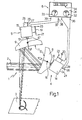
- Number in Fig.1 indicates a device for focusing and blending a laser beam ( 2 ) on a focusing surface (3).
- Device 1 essentially comprises two units (4, 5), for optical processing of beam 2 , and a processing and display unit (6), connected to the said units 4 and 5.
- the latter are identical and each comprise a round mirror (8, 9), with a spherical,. concave relfecting surface ( 1 0, 11 ), connected to the end of a shaft (1 2 , 13 ) on an electric motor (1 4 , 15 ) by means of an adjustable coupling ( 1 6, 1 7).
- the latter provides for adjusting the angle (a, B ) of each mirror (8, 9) in relation to the axis of the corresponding shaft (12, 13).
- the speed of shaft 12, 13 on motor 14, 15 is regulated by means of a speed variator consisting of a rheostat ( 1 8, 1 9) with its supply terminals (20, 2 2 and 21 , 23 ) connected to the negative and positive poles respectively of a d.c. supply source (not shown).
- a speed variator consisting of a rheostat ( 1 8, 1 9) with its supply terminals (20, 2 2 and 21 , 23 ) connected to the negative and positive poles respectively of a d.c. supply source (not shown).
- Each motor (14, 15 ) is assigned a speedometer dynamo (24, 25) the voltage at the terminals of which is proportional to the speed of the shaft on the respective motor.
- Each dynamo ( 24 , 25 ) is fitted with output terminals ( 2 6, 28 and 27, 29 ) each of which is connected to a respective terminal (36, 38 and 37, 39) on processing unit 6.
- the latter has a panel (31) fitted with two analogue indicators (3 2 , 33) showing the rotation speed of the shaft on each motor (14, 15).
- Panel 31 is also fitted with a 7-section logic display (34) showing the ratio between the shaft rotation speeds on motors 14 and 15.
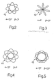
- Fig.s 2 to 5 show patterns (42, 43, 44, 45) drawn by the end of beam 2 on work surface 3, depending on the said angles a and B.
- angles a and R are set by means of couplings 16 and 1 7.
- the size of the angle determines the size and, in part, the shape of the patterns described on the focusing surface by beam 2 (see Fig.s 2, 3, 4 and 5).
- the speed of shafts 12 and 13 on motors 14 and 15 is than set using the slides on rheostats 1 8 and 19 , at the same time checking the indicators (32, 33 and 34) on unit 6.
- the speed the said shafts are set to determines the speed at which each pattern is drawn on the focusing surface, whereas the ratio between the said speeds determines the number of "petals" on each pattern. In our case, the said ratio is 0.75 for each of figures 2 to 5 which, as can be seen all have the same number of metals (7).
- Laser beam 2 which is horizontal in Fig. l , is intercep ted by surface 1 0 on concave mirror 8 which provides for initial focusing and directing the beam towards surface 1 1 on concave mirror 9. On leaving the latter, laser beam 2 is further focuses and aimed finally towards the preset working area on surface 3.
- Energy distribution on beam 2 is essentially uniform and covering a fairly wide area.
- the pattern described by beam 2 on surface 3 is determined by the combined motion produced by the rotation of mirrors 8 and 9, the actual design of the pattern being one of an essentially countless number produced by combining the various parameters on device 1.
- Device 1 provides.for easy, simultaneous focusing and blending of any type of laser beam with no need for the said focusing systems up- and downstream. What is more, device 1 is extremely cheap to prolude on account of the fact that units 4 and 5 are not only identical but also simple in design.
- two separate motors are used for turning mirrors 8 and 9 makes device 1 extremely versatile, in that each of the patterns described by laser beam 2 on working surface 3 may be completed over widely differing lengths of time.
- any fluctuation in the speed of motors 14 and 15 merely determines an open pattern, instead of a closed one as shown in Fig.s 2 to 5, which only serves to improve the blending function of device 1 further.
- changes can be made to the device ( 1 ) described by way of a non-limiting example, without, however, departing
- either of units 4, 5 could be limited sole ly to the concave mirror and regulating coupling and, vice versa, the drive of the other unit motor using a suitable drive chain.
Abstract
The present invention relates to a device (1) for focusing and blending a laser beam (2) on a work surface (3), the said device (1) comprising a pair of concave mirrors (8, 9), the first (8) of which reflects the incident laser beam towards the second (9) which, in turn, directs the beam (2) towards the said work surface. Furthermore, each mirror (8, 9) is turned by a respective motor (14, 15) round an axis other than the axis of symmetry of the mirror (8, 9) itself.
Description
- The present invention relates to a device for focusing and blending a power laser beam.
- Industrial application of power lasers for welding, cutting and surface heat treating metals is known to require specially designed optics which differ from one another according to the laser application involved. For welding or cutting metals, for example, the laser beam must be focused so as to produce a light spot with the smallest possible cross section on the focusing surface for which fixed or good-quality static optical.systems are preferably used.
- When using a power laser for surface heat treating metals, on the other hand, the light spot on the focusing surface must not only conform with preset dimensions but also present an energy distribution pattern as uniform as possible. As a major drawback on a laser beam is precisely uneven distribution of energy within its cross section, heat treating applications have required the design of new optical arrangements, known as dynamic systems, for blending the energy of the beam on the focusing surface. The term "blending" is essentially intended to mean distributing the energy of the laser beam as evenly as possible over its cross section. A known method of doing this consists in turning the laser beam round its own propagation axis by setting rotary mirrors up asymmetrically along the beam propagation path. This, however, requires an optical focusing system upstream, to limit the dimension of the mirrors, as well as a focusing system downstream, to obtain a light spot of the required size. Furthermore, to avoid problems involving cooling of the mirrors, care must be taken not to overconcentrate the laser beam using the upstream focusing system.
- The aim of the present invention is to provide a device for focusing and blending a laser beam, so as to overcome the drawbacks presented by the abovementioned known types.
- With this aim in view, the present invention relates to a device for focusing and blending a laser beam, characterised by the fact that it comprises :
- - at least a first and second mirror, each having a con cave reflecting surface, the laser beam for focusing and blending being directed on to the said first mirror and reflected on to the said second mirror from which it is directed on to a work surface;
- - drive means for turning each of the said mirrors round an axis other than the axis of symmetry of each of the said mirrors.
- A preferred arrangement of the device covered by the present invention will now be described, by way of a non-limiting example, with reference to the attached drawings, in which :
- - Fig.1 shows a diagram of the focusing and blending device covered by the present invention;
- - Fig.s 2, 3, 4 and 5 show a series of patterns produced by a laser beam on a focusing surface by adjusting a number of parameters on the Fig.1 device.
- Number in Fig.1 indicates a device for focusing and blending a laser beam (2) on a focusing surface (3). Device 1 essentially comprises two units (4, 5), for optical processing of beam 2, and a processing and display unit (6), connected to the
said units shaft motor - Each motor (14, 15) is assigned a speedometer dynamo (24, 25) the voltage at the terminals of which is proportional to the speed of the shaft on the respective motor. Each dynamo (24, 25) is fitted with output terminals (26, 28 and 27, 29) each of which is connected to a respective terminal (36, 38 and 37, 39) on processing unit 6. The latter has a panel (31) fitted with two analogue indicators (32, 33) showing the rotation speed of the shaft on each motor (14, 15).
Panel 31 is also fitted with a 7-section logic display (34) showing the ratio between the shaft rotation speeds onmotors - Fig.s 2 to 5 show patterns (42, 43, 44, 45) drawn by the end of beam 2 on
work surface 3, depending on the said angles a and B. - Operation of
device 1 is as follows. - First of all, angles a and R are set by means of
couplings 16 and 17. The size of the angle determines the size and, in part, the shape of the patterns described on the focusing surface by beam 2 (see Fig.s 2, 3, 4 and 5). The speed ofshafts motors rheostats 18 and 19, at the same time checking the indicators (32, 33 and 34) on unit 6. The speed the said shafts are set to determines the speed at which each pattern is drawn on the focusing surface, whereas the ratio between the said speeds determines the number of "petals" on each pattern. In our case, the said ratio is 0.75 for each of figures 2 to 5 which, as can be seen all have the same number of metals (7). - Once angles a and B and the speeds and ratio of
shafts 12 and 13 have been set,device 1 is ready to operate.Laser beam 2, which is horizontal in Fig.l, is intercep ted by surface 10 onconcave mirror 8 which provides for initial focusing and directing the beam towardssurface 11 on concave mirror 9. On leaving the latter, laser beam 2 is further focuses and aimed finally towards the preset working area onsurface 3. - Energy distribution on
beam 2 is essentially uniform and covering a fairly wide area. The pattern described bybeam 2 onsurface 3 is determined by the combined motion produced by the rotation ofmirrors 8 and 9, the actual design of the pattern being one of an essentially countless number produced by combining the various parameters ondevice 1. - The advantages of the present invention for focusing and blending a laser beam will be clear from the descrip tion given.
Device 1, in fact, provides.for easy, simultaneous focusing and blending of any type of laser beam with no need for the said focusing systems up- and downstream. What is more,device 1 is extremely cheap to pro duce on account of the fact thatunits mirrors 8 and 9 makes device 1 extremely versatile, in that each of the patterns described by laser beam 2 on working surface 3 may be completed over widely differing lengths of time. Furthermore, any fluctuation in the speed ofmotors - from the scope of the present invention.
- For example, either of
units
Claims (10)
1) - Device (1) for focusing and blending a laser beam (2), characterised by the fact that it comprises :
- at least a first and second mirror (8, 9), each having a concave reflecting surface (10, 11), the laser beam for focusing and blending being directed on to the said first mirror (8) and reflected on to the said second mirror (9) from which it is directed on to a work surface (3);
- drive means (14, 15) for turning each of the said mirrors (8, 9) round an axis other than the axis of symmetry of each of the said mirrors (14, 15).
2) - Device according to Claim 1, characterised by the fact that it comprises means for adjusting the angle of the said axes of rotation and symmetry.
3) - Device according to Claim 2, characterised by the fact that, for each of the said mirrors (8, 9), the said adjustment means comprise a coupling (16, 17) for connecting the said mirror (8, 9) to its respective drive means (14, 15).
4) - Device according to any of the foregoing Claims, characterised by the fact that the said drive means com prise at least one electric motor (14, 15) connected to one of the said mirrors (8, 9).
5) - Device according to Claim 4, characterised by the fact that it comprises means (18, 19) for regulating the speed of the said electric motor (14, 15).
6) - Device according to any of the foregoing Claims, characterised by the fact that it comprises means for generating electric signals proportional to the rotation speed of each of the said mirrors (8, 9).
7) - Device according to Claim 6 and depending on Claim 4 or 5, characterised by the fact that the said generat ing means consist of at least one speedometer dynamo (24, 25) powered by the said electric motor (14, 15).
8) - Device according to Claim 7, characterised by the fact that, for each of the said mirrors (8, 9), it comprises two separate control units (4, 5) each consisting of the said motor (14, 15), the said coupling (16, 17) and the said speedometer dynamo (24, 25).
9) - Device according to any of the foregoing Claims, characterised by the fact that it comprises a processing and indicator unit (6) showing the rotation speed of and/or the ratio between the said mirrors.
10) - Device according to Claim 9, depending on Claim 7 or 8, characterised by the fact that the said process- . ing and indicator unit (6) has inputs for receiving signals generated by the said speedometer dynamos (24, 25).
Applications Claiming Priority (2)
| Application Number | Priority Date | Filing Date | Title |
|---|---|---|---|
| IT6838682 | 1982-11-29 | ||
| IT68386/82A IT1157960B (en) | 1982-11-29 | 1982-11-29 | DEVICE TO FOCUS AND HOMOGENEIZE A LASER BEAM |
Publications (2)
| Publication Number | Publication Date |
|---|---|
| EP0110231A2 true EP0110231A2 (en) | 1984-06-13 |
| EP0110231A3 EP0110231A3 (en) | 1985-08-07 |
Family
ID=11309223
Family Applications (1)
| Application Number | Title | Priority Date | Filing Date |
|---|---|---|---|
| EP83111387A Withdrawn EP0110231A3 (en) | 1982-11-29 | 1983-11-14 | Device for focusing and blending a laser beam |
Country Status (3)
| Country | Link |
|---|---|
| EP (1) | EP0110231A3 (en) |
| JP (1) | JPS59111618A (en) |
| IT (1) | IT1157960B (en) |
Cited By (7)
| Publication number | Priority date | Publication date | Assignee | Title |
|---|---|---|---|---|
| WO1987005843A1 (en) * | 1986-03-26 | 1987-10-08 | Nauchno-Issledovatelsky Tsentr Po Tekhnologicheski | Installation for laser treatment of materials |
| EP0349347A1 (en) * | 1988-06-30 | 1990-01-03 | Kabushiki Kaisha Toshiba | Optical marking system having marking mode selecting function |
| US5198843A (en) * | 1988-06-30 | 1993-03-30 | Kabushiki Kaisha Toshiba | Optical marking system having marking mode selecting function |
| US5245563A (en) * | 1991-09-20 | 1993-09-14 | Kendall Square Research Corporation | Fast control for round unit |
| EP0732168A2 (en) * | 1995-03-15 | 1996-09-18 | Sumitomo Electric Industries, Limited | Method and device for focusing laser beam |
| GB2329724A (en) * | 1997-09-24 | 1999-03-31 | Samsung Electronics Co Ltd | A view selecting apparatus for an X-ray inspection system |
| DE102014012456A1 (en) * | 2014-08-21 | 2016-02-25 | Steinmeyer Mechatronik GmbH | Optical beam guiding unit and material processing device with an optical beam guiding unit |
Citations (4)
| Publication number | Priority date | Publication date | Assignee | Title |
|---|---|---|---|---|
| US3797908A (en) * | 1970-03-11 | 1974-03-19 | Atomic Energy Authority Uk | Optical arrangements and apparatus |
| US4017708A (en) * | 1974-07-12 | 1977-04-12 | Caterpillar Tractor Co. | Method and apparatus for heat treating an internal bore in a workpiece |
| US4049945A (en) * | 1973-10-10 | 1977-09-20 | Winkler & Dunnebier Maschinenfabrik Und Eisengiesserei Kg | Method of and apparatus for cutting material to shape from a moving web by burning |
| US4079230A (en) * | 1974-11-01 | 1978-03-14 | Hitachi, Ltd. | Laser working apparatus |
-
1982
- 1982-11-29 IT IT68386/82A patent/IT1157960B/en active
-
1983
- 1983-11-14 EP EP83111387A patent/EP0110231A3/en not_active Withdrawn
- 1983-11-28 JP JP58225324A patent/JPS59111618A/en active Pending
Patent Citations (4)
| Publication number | Priority date | Publication date | Assignee | Title |
|---|---|---|---|---|
| US3797908A (en) * | 1970-03-11 | 1974-03-19 | Atomic Energy Authority Uk | Optical arrangements and apparatus |
| US4049945A (en) * | 1973-10-10 | 1977-09-20 | Winkler & Dunnebier Maschinenfabrik Und Eisengiesserei Kg | Method of and apparatus for cutting material to shape from a moving web by burning |
| US4017708A (en) * | 1974-07-12 | 1977-04-12 | Caterpillar Tractor Co. | Method and apparatus for heat treating an internal bore in a workpiece |
| US4079230A (en) * | 1974-11-01 | 1978-03-14 | Hitachi, Ltd. | Laser working apparatus |
Cited By (10)
| Publication number | Priority date | Publication date | Assignee | Title |
|---|---|---|---|---|
| WO1987005843A1 (en) * | 1986-03-26 | 1987-10-08 | Nauchno-Issledovatelsky Tsentr Po Tekhnologicheski | Installation for laser treatment of materials |
| US4797532A (en) * | 1986-03-26 | 1989-01-10 | Maiorov Vladimir S | Apparatus for laser treatment of materials |
| EP0349347A1 (en) * | 1988-06-30 | 1990-01-03 | Kabushiki Kaisha Toshiba | Optical marking system having marking mode selecting function |
| US5198843A (en) * | 1988-06-30 | 1993-03-30 | Kabushiki Kaisha Toshiba | Optical marking system having marking mode selecting function |
| US5245563A (en) * | 1991-09-20 | 1993-09-14 | Kendall Square Research Corporation | Fast control for round unit |
| EP0732168A2 (en) * | 1995-03-15 | 1996-09-18 | Sumitomo Electric Industries, Limited | Method and device for focusing laser beam |
| EP0732168A3 (en) * | 1995-03-15 | 1997-04-09 | Sumitomo Electric Industries | Method and device for focusing laser beam |
| US5889626A (en) * | 1995-03-15 | 1999-03-30 | Sumitomo Electric Industries, Ltd. | Method and device for focusing laser beam |
| GB2329724A (en) * | 1997-09-24 | 1999-03-31 | Samsung Electronics Co Ltd | A view selecting apparatus for an X-ray inspection system |
| DE102014012456A1 (en) * | 2014-08-21 | 2016-02-25 | Steinmeyer Mechatronik GmbH | Optical beam guiding unit and material processing device with an optical beam guiding unit |
Also Published As
| Publication number | Publication date |
|---|---|
| EP0110231A3 (en) | 1985-08-07 |
| IT8268386A0 (en) | 1982-11-29 |
| IT1157960B (en) | 1987-02-18 |
| JPS59111618A (en) | 1984-06-27 |
Similar Documents
| Publication | Publication Date | Title |
|---|---|---|
| US4822974A (en) | Laser hold drilling system with lens and two wedge prisms including axial displacement of at least one prism | |
| US10444521B2 (en) | Device for machining material by means of laser radiation | |
| US4370540A (en) | Reflective beam rotator | |
| US5587094A (en) | Laser marking apparatus | |
| CN103955061A (en) | Uniform light spot surface scanning device of laser cleaning machine | |
| EP0110231A2 (en) | Device for focusing and blending a laser beam | |
| US3993402A (en) | Apparatus for directing a laser beam | |
| JPH0380596B2 (en) | ||
| US4499362A (en) | Rotary beam chopper with continuously variable duty cycle | |
| US4491383A (en) | Device for modifying and uniforming the distribution of the intensity of a power laser beam | |
| EP0025594A1 (en) | Axis-monitoring apparatus for a laser beam | |
| US5365032A (en) | Method of cutting by means of laser radiation | |
| CN110133842A (en) | A kind of galvanometer scanning device and system | |
| EP1162024A2 (en) | Laser machining apparatus | |
| CN207488877U (en) | A kind of hand held laser spot size regulating device | |
| US4363539A (en) | Photohead with flashing beam | |
| EP0022825B1 (en) | Method of treating a workpiece by directing a beam of radiation on to it | |
| JPS59107785A (en) | Multijoint arm type robot for laser working | |
| CN209911649U (en) | Galvanometer scanning device and system | |
| JPH058072A (en) | Laser beam machining method | |
| JPS5647288A (en) | Laser working apparatus | |
| JPH04200886A (en) | Laser marking device | |
| RU7040U1 (en) | DEVICE FOR LASER SUPPLYING OF PARTS MADE FROM DIFFICULTLY WELDABLE MATERIALS | |
| JPS63188470A (en) | Laser soldering equipment | |
| JPS58161388A (en) | Laser beam printer |
Legal Events
| Date | Code | Title | Description |
|---|---|---|---|
| PUAI | Public reference made under article 153(3) epc to a published international application that has entered the european phase |
Free format text: ORIGINAL CODE: 0009012 |
|
| AK | Designated contracting states |
Designated state(s): AT BE CH DE FR GB LI NL SE |
|
| PUAL | Search report despatched |
Free format text: ORIGINAL CODE: 0009013 |
|
| AK | Designated contracting states |
Designated state(s): AT BE CH DE FR GB LI NL SE |
|
| STAA | Information on the status of an ep patent application or granted ep patent |
Free format text: STATUS: THE APPLICATION HAS BEEN WITHDRAWN |
|
| 18W | Application withdrawn |
Withdrawal date: 19851121 |
|
| RIN1 | Information on inventor provided before grant (corrected) |
Inventor name: FERRARI, GIANCARLO Inventor name: PERA, LUCIANO |