EP0349110B1 - Procédé et dispositif de mesure radar dans le sol - Google Patents
Procédé et dispositif de mesure radar dans le sol Download PDFInfo
- Publication number
- EP0349110B1 EP0349110B1 EP89304938A EP89304938A EP0349110B1 EP 0349110 B1 EP0349110 B1 EP 0349110B1 EP 89304938 A EP89304938 A EP 89304938A EP 89304938 A EP89304938 A EP 89304938A EP 0349110 B1 EP0349110 B1 EP 0349110B1
- Authority
- EP
- European Patent Office
- Prior art keywords
- antenna assembly
- data
- output
- assembly
- sampling unit
- Prior art date
- Legal status (The legal status is an assumption and is not a legal conclusion. Google has not performed a legal analysis and makes no representation as to the accuracy of the status listed.)
- Expired
Links
- 238000000034 method Methods 0.000 title claims description 13
- 238000005070 sampling Methods 0.000 claims description 22
- 230000004044 response Effects 0.000 claims description 8
- 239000004020 conductor Substances 0.000 claims description 4
- 230000005670 electromagnetic radiation Effects 0.000 claims description 4
- 230000008878 coupling Effects 0.000 claims description 2
- 238000010168 coupling process Methods 0.000 claims description 2
- 238000005859 coupling reaction Methods 0.000 claims description 2
- 230000001960 triggered effect Effects 0.000 claims description 2
- 239000004033 plastic Substances 0.000 description 16
- 229920003023 plastic Polymers 0.000 description 16
- 238000005253 cladding Methods 0.000 description 5
- 239000000463 material Substances 0.000 description 5
- 238000012986 modification Methods 0.000 description 5
- 230000005855 radiation Effects 0.000 description 5
- 230000009471 action Effects 0.000 description 4
- 230000000712 assembly Effects 0.000 description 4
- 238000000429 assembly Methods 0.000 description 4
- 230000004048 modification Effects 0.000 description 4
- 239000006096 absorbing agent Substances 0.000 description 3
- RYGMFSIKBFXOCR-UHFFFAOYSA-N Copper Chemical compound [Cu] RYGMFSIKBFXOCR-UHFFFAOYSA-N 0.000 description 2
- 235000004443 Ricinus communis Nutrition 0.000 description 2
- 230000008859 change Effects 0.000 description 2
- 238000010276 construction Methods 0.000 description 2
- 229910052802 copper Inorganic materials 0.000 description 2
- 239000010949 copper Substances 0.000 description 2
- 238000010586 diagram Methods 0.000 description 2
- 239000003989 dielectric material Substances 0.000 description 2
- 230000033001 locomotion Effects 0.000 description 2
- 229910052751 metal Inorganic materials 0.000 description 2
- 239000002184 metal Substances 0.000 description 2
- 230000008569 process Effects 0.000 description 2
- 239000000725 suspension Substances 0.000 description 2
- 229910000838 Al alloy Inorganic materials 0.000 description 1
- 208000002193 Pain Diseases 0.000 description 1
- 230000005540 biological transmission Effects 0.000 description 1
- 238000006243 chemical reaction Methods 0.000 description 1
- 238000013480 data collection Methods 0.000 description 1
- 230000014509 gene expression Effects 0.000 description 1
- 230000000977 initiatory effect Effects 0.000 description 1
- 238000004519 manufacturing process Methods 0.000 description 1
- 230000003287 optical effect Effects 0.000 description 1
- 230000036407 pain Effects 0.000 description 1
- 239000011435 rock Substances 0.000 description 1
- 238000003860 storage Methods 0.000 description 1
- 230000000007 visual effect Effects 0.000 description 1
Images


Classifications
-
- G—PHYSICS
- G01—MEASURING; TESTING
- G01S—RADIO DIRECTION-FINDING; RADIO NAVIGATION; DETERMINING DISTANCE OR VELOCITY BY USE OF RADIO WAVES; LOCATING OR PRESENCE-DETECTING BY USE OF THE REFLECTION OR RERADIATION OF RADIO WAVES; ANALOGOUS ARRANGEMENTS USING OTHER WAVES
- G01S13/00—Systems using the reflection or reradiation of radio waves, e.g. radar systems; Analogous systems using reflection or reradiation of waves whose nature or wavelength is irrelevant or unspecified
- G01S13/02—Systems using reflection of radio waves, e.g. primary radar systems; Analogous systems
- G01S13/0209—Systems with very large relative bandwidth, i.e. larger than 10 %, e.g. baseband, pulse, carrier-free, ultrawideband
-
- G—PHYSICS
- G01—MEASURING; TESTING
- G01V—GEOPHYSICS; GRAVITATIONAL MEASUREMENTS; DETECTING MASSES OR OBJECTS; TAGS
- G01V3/00—Electric or magnetic prospecting or detecting; Measuring magnetic field characteristics of the earth, e.g. declination, deviation
- G01V3/12—Electric or magnetic prospecting or detecting; Measuring magnetic field characteristics of the earth, e.g. declination, deviation operating with electromagnetic waves
-
- G—PHYSICS
- G01—MEASURING; TESTING
- G01V—GEOPHYSICS; GRAVITATIONAL MEASUREMENTS; DETECTING MASSES OR OBJECTS; TAGS
- G01V3/00—Electric or magnetic prospecting or detecting; Measuring magnetic field characteristics of the earth, e.g. declination, deviation
- G01V3/15—Electric or magnetic prospecting or detecting; Measuring magnetic field characteristics of the earth, e.g. declination, deviation specially adapted for use during transport, e.g. by a person, vehicle or boat
-
- G—PHYSICS
- G01—MEASURING; TESTING
- G01S—RADIO DIRECTION-FINDING; RADIO NAVIGATION; DETERMINING DISTANCE OR VELOCITY BY USE OF RADIO WAVES; LOCATING OR PRESENCE-DETECTING BY USE OF THE REFLECTION OR RERADIATION OF RADIO WAVES; ANALOGOUS ARRANGEMENTS USING OTHER WAVES
- G01S13/00—Systems using the reflection or reradiation of radio waves, e.g. radar systems; Analogous systems using reflection or reradiation of waves whose nature or wavelength is irrelevant or unspecified
- G01S13/88—Radar or analogous systems specially adapted for specific applications
- G01S13/885—Radar or analogous systems specially adapted for specific applications for ground probing
Definitions
- the invention relates to ground probing radar methods and apparatus, particularly though not exclusively for use in locating buried pipes.
- a ground probing radar method comprises moving an antenna assembly over the ground while the assembly is rotating about an axis directed into the ground and is transmitting and receiving electromagnetic radiation, producing data in response to rotation of the antenna assembly about said axis and using said data to control successive energisations of the antenna assembly.
- Ground probing radar apparatus comprises a support assembly which can be moved over the ground, an antenna assembly mounted on the support assembly so as to be rotatable about an axis directed into the ground, a drive motor mounted on the support assembly and connected to the antenna assembly so as to be able to rotate it about said axis, and means operable in response to rotation of the antenna assembly about said axis to produce data representative of the angular position of the antenna assembly about said axis.
- the support assembly comprises wheels on which the assembly runs over the ground.
- Preferably said data is used to initiate the energisation of the antenna assembly to emit radiation therefrom.
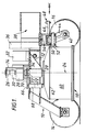
- Figures 1 & 2 show the following main items: a support assembly 10 comprising a chassis 12 mounted on four ground wheels, the leading pair 14 being on fixed axles and the trailing pair 16 being mounted for castor action; an encoder 17 (Figure 2) driven by rotation of one of the rear wheels 16; an antenna assembly 18 carried on a vertical, hollow shaft 20 beneath the chassis 12; an electric drive motor 22 for rotating the antenna assembly 18 about a vertical axis 24; a two-channel microwave rotating connector assembly 26 at the upper end of the shaft 20; and an encoder 28 driven by rotation of the shaft 20.
- a support assembly 10 comprising a chassis 12 mounted on four ground wheels, the leading pair 14 being on fixed axles and the trailing pair 16 being mounted for castor action
- an encoder 17 ( Figure 2) driven by rotation of one of the rear wheels 16
- an antenna assembly 18 carried on a vertical, hollow shaft 20 beneath the chassis 12
- an electric drive motor 22 for rotating the antenna assembly 18 about a vertical axis 24
- a two-channel microwave rotating connector assembly 26 at the upper end
- Figure 1 also shows the following parts of the electronics carried by the support assembly though they are omitted from Figure 2:- an impulse generator and control unit 30; a sampling unit 32; a delay line assembly 34; power supplies, regulators and analogue-to-digital convertor at 36; and a digital signal processor 38.
- the support assembly is intended to be pushed by an operative holding a handle (not shown) attached at pivot connections 39 at each side of the assembly, with the wheels 14 leading.
- the operative pushes the handle sideways so that the assembly turns to one side or the other. This action is facilitated by the castor action of the rear wheels 16.
- the rotational axis 40 of each wheel 16 is offset rearwardly from the corresponding vertical axis 42 about which the trunnion 44 of the wheel can turn.
- the trunnions 44 have integral arms 46 each pivotally connected at 48 to a transverse tie-bar (not shown) so that the wheels 16 turn in synchronism about their vertical pivot axes 42.
- the trunnions 44 are pivotally connected about the axes 42 to a common cross-piece 50, which can rock about a horizontal pin 52 connecting the cross-piece 50 to a bracket 54 secured to the chassis 12.
- the support assembly 10 accordingly is effectively supported at three points i.e. the two front wheels 14 and the mid-point of the cross-piece 50.
- the encoder 17 is driven by a pulley 19 around which passes an endless belt 21.
- the belt also passes around a pulley 23 secured to a shaft 25 on which one of the rear wheels 16 is mounted.
- the chassis 12 is constructed of synthetic plastics material so far as possible particularly above the top of the antenna assembly or close to the antenna assembly.
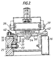
- the antenna assembly comprises two interleaved mutually orthogonal logarithmic spirals formed as etched copper layers on an insulative support sheet. Typically, when energised such transmit elements emit circularly polarised electromagnetic radiation.
- the copper layers are on the underside of the sheet which extends horizontally across the inside of a cylindrical drum 60 of synthetic plastics material. The board is near the lower edge of the drum 60.
- Figure 2A shows the support sheet 13 which is shown with cladding 15 of dielectric material extending across the underside of the sheet immediately against the antenna elements, which are so thin that they are not visible in section.
- the right-hand side of the Figure 2A shows a thicker slab of cladding 117 which may be preferred.
- the emitter elements are energised via a microwave conductor 119 including baluns 121, 123.
- a similar conductor (not shown) energises the receive elements.
- the absorber material is indicated at 125 in the upper part of the drum 60.
- the cladding 15 or 117 may be dispensed with for some applications.
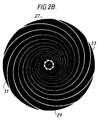
- Figure 2B shows the antenna elements. Although eight spiral arms are present, only four are used in this embodiment, namely transmit elements 27 and 29 and receive elements 31 and 33. The remaining four intermediate elements are not used and are terminated by load resistors (not shown).
- Figure 2A also shows the bearings at 35, 37 by which the antenna assembly 18 is rotatably supported.
- the board there is a body of dielectric material which absorbs electromagnetic radiation.
- the absorber at the level 62 there is a horizontal metal wall to act as a reflector of unwanted radiation.
- the reflected radiation is out of phase with the radiation emitted downwardly by the elements formed by the arms of the spiral on the board and so does not diminish the emitted signal.
- the shaft 20 is supported by two bearings and the motor 22 drives a pulley 66 via a gearbox 68, the pulley being connected by a belt 70 to a pulley 72 on the shaft 20.
- the transmit and receive elements of the antenna formed by the arms of the interleaved spirals are connected via baluns within the drum 60 by two leads which pass upwardly through the shaft 20.
- the leads are connected to two corresponding parts of the microwave connector assembly 26, which parts rotate with the antenna assembly 18. Those parts transfer the signals from and to two corresponding fixed parts of the connector assembly 26 which are supported by a fixed bracket assembly 74 secured to the chassis 12.
- the two fixed parts of the connector assembly 26 are connected to respective input and output terminals.
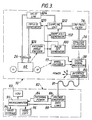
- the input terminal is connected via microwave cable to the impulse generator 130 ( Figure 3) and the output terminal is connected via microwave cable to the delay line 134 ( Figure 3) and thence to the sampling unit 32. From the sampling unit 132 the received signal passes to a low-pass filter 78 and thence to the analogue-to-digital stage at 36, followed by the digital signal processor 38.
- the signal passes via interface connectors 80 to an umbilical cable 81 which trails from the support assembly 10.
- the umbilical extends to a support facility 82 which typically is carried on a vehicle such as an automobile truck or van and which includes a power supply 84 from which power is passed through the umbilical to the electronic circuitry on the support assembly 10 via the interface connectors 80.
- the support facility 82 also comprises a voltage convertor 86, data links 88, a micro-computer 90, a visual display unit 92, hard-storage facility 94 and hard copy production facility 96.
- the wheel encoder 17 produces pulses representative of travel of the support assembly 10 over the ground and that first data passes to the digital signal processor 38.
- the antenna assembly shaft encoder 128 produces pulses which are also fed to the digital signal processor 38.
- the support assembly also carries a pulse set generator 100 and a ramp voltage generator 102.
- the first data pulses from the shaft encoder 128 are fed to both of those generators 100, generator 100 is fed to the impulse generator 130.
- the output from the ramp voltage generator 102 is also fed to the sampling unit 132.
- the support assembly 10 is wheeled over the ground by an operative. Typically, the assembly 10 is made to follow successive straight courses parallel to each other and spaced apart some 10 centimetres. As the assembly 10 travels along a course the wheel encoder 17 continuously produces first data pulses.
- the antenna assembly 18 is rotated continuously by the motor 22 and the shaft encoder 28 produces a second data pulse at each successive angular interval. For example, the antenna assembly 18 rotates at 40 revolutions per minute and the encoder 28 produces 1600 pulses per revolution of the antenna assembly 18.
- every fourth pulse is used by the pulse set generator 100 to initiate a set of 256 microwave pulses which, after suitable conversion by the impulse generator 30 are transmitted from the transmit elements of the antenna assembly 18. The time between the transmitted pulses is 12 micro-seconds.
- the rate of rotation of the antenna assembly 18, and the number and repetition frequency of the transmitted pulses in each set are chosen so that the transmission of each set is completed before the initiation of the succeeding set.
- the running time of the voltage ramp produced by the generator 102 is the same as the duration of each set of pulses.
- the rate of rotation of the antenna assembly 18 and the duration and frequency of the pulse sets are also chosen to suit an acceptable rate of travel of the support assembly over the ground and to ensure that the successive sets of pulses are transmitted at suitable intervals along the course for example at intervals of 10 centimetres if the support assembly travels at a linear rate of 8 metres per minute.
- the pulses After emission from the antenna transmit elements, the pulses are scattered by the ground and objects buried in the ground. A small proportion of reflected electromagnetic energy strikes the antenna receive elements and produces received data which passes from the antenna to the sampling unit 32.
- the sampling unit 32 outputs a set of analogue voltage levels equal in number to the number of pulses in each set of transmitted pulses. After passing through the low-pass filter 78 to the analogue-to-digital convertor 36, a set of digitised voltage levels results. They are passed via the umbilical 81 to the microcomputer 90.
- the control signals for the various processes in the system are handled by the microprocessor of the computer 90.
- In and Qn are the nth values of the waveforms I and Q each of which has N values.
- the waveforms I, Q are combined with corresponding reference waveforms derived from data received when a reference object is irradiated with output from the antenna assembly.
- the combination is such that indications can be derived of the orientation and depth of buried objects such as pipes and cables. Further information about such combination is contained in our co-pending patent application GB-A-2188506.
- the first data i.e. the output pulses from the wheel encoder 17 are used as a convenient way of providing a location in terms of distance travelled from a start point on a particular survey line.
- the speed at which the operator moves the assembly over the ground determines the distance travelled between successive sets of pulses emitted from the antenna. In this case, the times between such sets remains constant throughout.
- the distance travelled between successive sets remains constant.
- the data produced by the wheel encoder 17 is used with a clock output to derive the rate of travel of the assembly.
- the rate is used with the second data from the antenna encoder 128 to ensure that the centre points of successive increments of travel (over which the successive sets of pulses are emitted) are separated by equal distances.
- the antenna elements may be provided with dielectric cladding positioned between the elements and the ground as described in our co-pending GB-A-2188506.
- power for the components on the support assembly 10 can be provided by batteries.
- Data can be transmitted from the assembly by radiation e.g. light, infra-red, radio so as to eliminate the need for an umbilical connection between the assembly 10 and the support facility 82.
- data can be stored on the assembly 10 instead of being transmitted in real time.
- Data could be down-loaded periodically by bringing the assembly 10 to the support facility 82 and engaging physical data links e.g. plug and socket connectors.
- Figure 4 shows another modification in which, in a modified support assembly 198, the impulse generator 130 is mounted on a modified antenna assembly 200.
- the pulse set generator 100 is also mounted on the antenna assembly 200.
- the rotating microwave connector 202 provides only a single channel i.e. for received data.
- the encoder 128 is reversed so that its output port rotates with the antenna assembly 200.
- the sampling unit 132 is triggered by the received signal.
- a relatively large trigger pulse must be added onto the front of each received data pulse train. This is achieved by using the trigger take-off as shown in Figure 4.
- the supply of power to the circuitry on the rotating antenna assembly 200 can be provided by means of a radiative-transfer coupling arrangement (not shown) which couples power into the microwave cable which connects the receive antenna elements to the single-channel connector 202. Such power transfer does not interfere with the received data conveyed by the core conductor of such a cable.
- Figure 4 can be powered from batteries on board the support assembly or from mains via an umbilical.
- the trigger pulse mentioned above is derived from motion of the antenna assembly using a light source such as a light-emitting diode and light sensors which source and sensors are moved relatively by the rotation of the antenna assembly.
- the encoder 17 is only one example of how data representative of the position of the support assembly can be derived for recording in the support facility 82. It is not essential to use an encoder or other device to respond to wheel rotation. Instead for example the support assembly can be mounted on a boom which is rotatably mounted or otherwise movable mounted e.g. on the vehicle which carries the support facility 82. In such a case, movement of the boom can be used to drive an encoder in response to the rotation of the boom about a known axis and also, if required, extension of the boom by telescopic action say can be used to drive a second encoder in response to change in boom length.
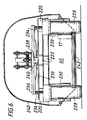
- a square plate 210 of aluminium alloy measures, for example, 60 x 60 centimeters, is placed above the antenna drum 60. If the plate is made thick enough to form the chassis of the support assembly. Virtually all the structure below the chassis 210 is made of plastics material. This plate 210 produces a large amount of RF shielding of the metalwork of the electronic units mounted on the upper side of the plate 210.
- the plate 210 is square in order to provide 4-fold symmetry of shielding.
- the electronic boxes (not shown) are mounted on the plate 210 and do not overhang the edge. If the box height exceeds a few centimeters, for example 7.5 centimeters, a square annulus of microwave absorber must be placed arount them.
- the encoder beneath the chassis 210 operates by detecting a light beam interrupted by a toothed wheel rotating with a wheel. Optical fibres are used to feed light to the toothed wheel and to conduct signals encoding the rotation.
- the wheels cannot exactly provide 4-fold symmetry and are placed at experimentally determined positions to reduct their influence to a minimum.
- the square plate 210 is shown supported on two plastics side blocks 220 and two plastics end blocks 222.
- the side blocks 220 each support like ends of two pains of oppositely extending plastics leaf springs 224.
- the opposite ends of the leaf springs 224 are jointed by a plastics block 226.
- Each block 226 supports a wheel 228 on a trunnion 230.
- Each end block 222 supports the like ends of two pairs of oppositely extending plastics leaf springs 232. The opposite ends of these springs are jointed by one of the blocks 226.
- a plastics screwed rod 234 extends upwardly from each block 226 and through a hole in the plate 210.
- the rods 234 of each pair at the ends of the support assembly engage the underside of a plastics pivot arm assembly 236 which is pivotted upon a pivot pin 238 on a plastics block 240 mounted on the plate 210 above the blocks 222.
- One of the assemblies 236 is preferably prevented from turning on its pivot pin 238.
- Each wheel is thus mounted on two pairs of leaf springs, the side springs 224 and the end springs 232 which mainly ensure that the wheel is kinematically located with respect to the chassis and can move vertically.
- the assemblies 236 provide the principal spring stiffness and by having one assembly 236 non-pivotting on its pin 238 a three-point suspension is achieved.
- the spring assemblies 236 can be replaced by pneumatic spring assemblies in a modified arrangement. Instead of leaf springs 224, 232, plastic links pin-jointed at their ends can be used for the suspension.
- the support assembly includes a plastics overcover 240 and a plastics undercover 242.
- the wheels 228 are made of plastics material and as far as possible the whole of the construction beneath the metal plate 210 presents 4-fold symmetry to the antenna.
- a plastics handle 244 is provided which can be swung over the assembly to either position, so that the assembly can be driven in either direction.
Landscapes
- Remote Sensing (AREA)
- Engineering & Computer Science (AREA)
- Physics & Mathematics (AREA)
- Life Sciences & Earth Sciences (AREA)
- Radar, Positioning & Navigation (AREA)
- General Physics & Mathematics (AREA)
- General Life Sciences & Earth Sciences (AREA)
- Geophysics (AREA)
- Environmental & Geological Engineering (AREA)
- Geology (AREA)
- Computer Networks & Wireless Communication (AREA)
- Electromagnetism (AREA)
- Radar Systems Or Details Thereof (AREA)
- Variable-Direction Aerials And Aerial Arrays (AREA)
- Geophysics And Detection Of Objects (AREA)
Claims (10)
Applications Claiming Priority (4)
| Application Number | Priority Date | Filing Date | Title |
|---|---|---|---|
| GB888812705A GB8812705D0 (en) | 1988-05-27 | 1988-05-27 | Ground probing radar method & apparatus |
| GB8812705 | 1988-05-27 | ||
| GB8908022A GB2224408B (en) | 1988-05-27 | 1989-04-10 | Ground probing radar method & apparatus |
| GB8908022 | 1989-04-10 |
Publications (3)
| Publication Number | Publication Date |
|---|---|
| EP0349110A2 EP0349110A2 (fr) | 1990-01-03 |
| EP0349110A3 EP0349110A3 (en) | 1990-04-04 |
| EP0349110B1 true EP0349110B1 (fr) | 1992-03-11 |
Family
ID=26293948
Family Applications (1)
| Application Number | Title | Priority Date | Filing Date |
|---|---|---|---|
| EP89304938A Expired EP0349110B1 (fr) | 1988-05-27 | 1989-05-16 | Procédé et dispositif de mesure radar dans le sol |
Country Status (6)
| Country | Link |
|---|---|
| US (1) | US4967199A (fr) |
| EP (1) | EP0349110B1 (fr) |
| JP (1) | JPH0285789A (fr) |
| CA (1) | CA1332847C (fr) |
| DE (1) | DE68900965D1 (fr) |
| ES (1) | ES2029553T3 (fr) |
Cited By (1)
| Publication number | Priority date | Publication date | Assignee | Title |
|---|---|---|---|---|
| US11952537B2 (en) | 2022-07-22 | 2024-04-09 | Ripcord Energy Solutions, LLC | Removal of hydrogen sulfide and/or mercaptans from oil or oil derivatives and treatment compositions for accomplishing the same |
Families Citing this family (28)
| Publication number | Priority date | Publication date | Assignee | Title |
|---|---|---|---|---|
| GB8907090D0 (en) * | 1989-03-29 | 1989-05-10 | British Gas Plc | Vehicle with plastics suspension |
| JPH0449889U (fr) * | 1990-08-31 | 1992-04-27 | ||
| JPH0587945A (ja) * | 1991-09-27 | 1993-04-09 | Doro Hozen Gijutsu Center | 舗装道路の空洞探査方法 |
| US5227799A (en) * | 1992-03-09 | 1993-07-13 | Mitsui Engineering & Shipbuilding Co., Ltd. | Road void search radar system |
| US5420589A (en) * | 1993-06-07 | 1995-05-30 | Wells; C. T. | System for evaluating the inner medium characteristics of non-metallic materials |
| US5835053A (en) * | 1993-06-28 | 1998-11-10 | Road Radar Ltd. | Roadway ground penetrating radar system |
| US5592170A (en) * | 1995-04-11 | 1997-01-07 | Jaycor | Radar system and method for detecting and discriminating targets from a safe distance |
| US5607205A (en) * | 1995-06-06 | 1997-03-04 | Caterpillar Inc. | Object responsive implement control system |
| GB9601528D0 (en) * | 1996-01-25 | 1996-03-27 | Chignell Richard J | Underground pipe locating system |
| US5673050A (en) * | 1996-06-14 | 1997-09-30 | Moussally; George | Three-dimensional underground imaging radar system |
| US5936233A (en) * | 1998-02-26 | 1999-08-10 | The Curators Of The University Of Missouri | Buried object detection and neutralization system |
| GB2336485B (en) * | 1998-04-14 | 2002-12-11 | Roke Manor Research | Monopulse generator |
| NL1016363C2 (nl) * | 2000-10-09 | 2002-04-10 | T & A Radar B V | Werkwijze voor bodemonderzoek, en inrichting voor het uitvoeren van de werkwijze. |
| WO2002004987A2 (fr) | 2000-07-07 | 2002-01-17 | T & A Survey B.V. | Antenne radar 3d pour trou de sonde et algorithme, procede et appareil de sonde en subsurface |
| US6388629B1 (en) | 2000-11-01 | 2002-05-14 | Witten Technologies, Inc. | Rotating scanning antenna apparatus and method for locating buried objects |
| SE524470C2 (sv) * | 2002-12-13 | 2004-08-10 | Malaa Geoscience Foervaltnings | Anordning för insamling av polarimetrisk data från markradar |
| US6949435B2 (en) | 2003-12-08 | 2005-09-27 | Sharp Laboratories Of America, Inc. | Asymmetric-area memory cell |
| US7755360B1 (en) | 2005-10-24 | 2010-07-13 | Seektech, Inc. | Portable locator system with jamming reduction |
| IL186884A (en) * | 2007-10-24 | 2014-04-30 | Elta Systems Ltd | Object simulation system and method |
| CN102621530B (zh) * | 2012-04-17 | 2014-03-19 | 水利部交通运输部国家能源局南京水利科学研究院 | 基于单片机的探地雷达的等距提示装置 |
| US8970435B2 (en) | 2012-10-05 | 2015-03-03 | Cambridge Silicon Radio Limited | Pie shape phased array antenna design |
| CN104701617B (zh) * | 2015-03-20 | 2016-06-08 | 中国矿业大学(北京) | 一种用于城市地下管线探地雷达的三维旋转天线系统 |
| GB201520829D0 (en) * | 2015-11-25 | 2016-01-06 | Univ Newcastle | Methods for forming 3D image data and associated apparatuses |
| US11029402B2 (en) * | 2016-03-07 | 2021-06-08 | The University Of Vermont And State Agricultural College | Wideband ground penetrating radar system and method |
| EP3220024B1 (fr) * | 2016-03-15 | 2021-01-06 | Hamilton Sundstrand Corporation | Clapet anti-retour |
| CN105826678A (zh) * | 2016-06-02 | 2016-08-03 | 中国矿业大学(北京) | 一种900m探地雷达天线外壳 |
| WO2018161182A1 (fr) * | 2017-03-10 | 2018-09-13 | Proceq Sa | Dispositif de sondage électromagnétique d'un échantillon |
| US10476152B2 (en) * | 2017-12-15 | 2019-11-12 | United States Of America As Represented By Secretary Of The Navy | System and method for automatic real time control of the rotational speed of a radar antenna |
Family Cites Families (8)
| Publication number | Priority date | Publication date | Assignee | Title |
|---|---|---|---|---|
| GB1569601A (en) * | 1976-05-18 | 1980-06-18 | Decca Ltd | Pulse radar apparatus |
| JPS59794B2 (ja) * | 1980-07-31 | 1984-01-09 | 防衛庁技術研究本部長 | 回転するアンテナを持つ埋設物探知装置 |
| JPS59793B2 (ja) * | 1980-07-31 | 1984-01-09 | 防衛庁技術研究本部長 | 回転するアンテナを持つ埋設物探知装置 |
| JPS60263880A (ja) * | 1984-06-12 | 1985-12-27 | Nippon Telegr & Teleph Corp <Ntt> | 地下埋設物探査方法 |
| GB8426245D0 (en) * | 1984-10-17 | 1984-11-21 | British Gas Corp | Microwave reflection survey equipment |
| GB8426246D0 (en) * | 1984-10-17 | 1984-11-21 | British Gas Corp | Microwave reflection survey equipment |
| US4698634A (en) * | 1985-07-10 | 1987-10-06 | Alongi Anthony V | Subsurface inspection radar |
| GB8607705D0 (en) * | 1986-03-27 | 1986-04-30 | British Gas Corp | Signal processing |
-
1989
- 1989-05-16 EP EP89304938A patent/EP0349110B1/fr not_active Expired
- 1989-05-16 DE DE8989304938T patent/DE68900965D1/de not_active Expired - Lifetime
- 1989-05-16 ES ES198989304938T patent/ES2029553T3/es not_active Expired - Lifetime
- 1989-05-26 CA CA000600787A patent/CA1332847C/fr not_active Expired - Fee Related
- 1989-05-26 US US07/357,532 patent/US4967199A/en not_active Expired - Fee Related
- 1989-05-29 JP JP1135696A patent/JPH0285789A/ja active Pending
Cited By (1)
| Publication number | Priority date | Publication date | Assignee | Title |
|---|---|---|---|---|
| US11952537B2 (en) | 2022-07-22 | 2024-04-09 | Ripcord Energy Solutions, LLC | Removal of hydrogen sulfide and/or mercaptans from oil or oil derivatives and treatment compositions for accomplishing the same |
Also Published As
| Publication number | Publication date |
|---|---|
| EP0349110A2 (fr) | 1990-01-03 |
| CA1332847C (fr) | 1994-11-01 |
| EP0349110A3 (en) | 1990-04-04 |
| ES2029553T3 (es) | 1992-08-16 |
| US4967199A (en) | 1990-10-30 |
| JPH0285789A (ja) | 1990-03-27 |
| DE68900965D1 (de) | 1992-04-16 |
Similar Documents
| Publication | Publication Date | Title |
|---|---|---|
| EP0349110B1 (fr) | Procédé et dispositif de mesure radar dans le sol | |
| US6388629B1 (en) | Rotating scanning antenna apparatus and method for locating buried objects | |
| US5745225A (en) | Apparatus for measuring a shape of road surface | |
| US4413907A (en) | Remote control surveying | |
| US4733737A (en) | Drivable steerable platform for industrial, domestic, entertainment and like uses | |
| EP1730616B1 (fr) | Système de traitement de surfaces | |
| WO2022065587A1 (fr) | Drone de mesure de distance | |
| US7339540B2 (en) | Sparse and virtual array processing for rolling axle array system | |
| US7183989B2 (en) | Transportable rolling radar platform and system | |
| CN102540185B (zh) | 一种阵列天线弧形扫描的毫米波成像系统成像的方法 | |
| US7199764B2 (en) | Maintenance platform for a rolling radar array | |
| CN106052663A (zh) | 相干测风激光雷达中提高方位角测量精度的装置及方法 | |
| US4261617A (en) | Method of controlling the working motion of a cutting tool of a tunnel-driving machine over the breast, and apparatus for carrying out the method | |
| CZ26196A3 (en) | System, consisting of a mobile vehicle, preferably a golf cart and a transmitter | |
| WO2008017486A1 (fr) | Dispositif de détermination de position | |
| GB2224408A (en) | Ground probing radar | |
| CN111239074A (zh) | 太赫兹检测机器人及检测方法 | |
| CN110907940A (zh) | 一种三维激光雷达 | |
| EP0453905A2 (fr) | Procédé et dispositif de détermination d'un objet mobile relativement à un obstacle | |
| US11960044B2 (en) | Discrete volumetric acoustic and resistivity method and apparatus for sub-seabed surveying | |
| CN114966694A (zh) | 适合于fmcw信号的距离多普勒成像算法 | |
| CN220164032U (zh) | 一种探地雷达遥控搭载小车 | |
| FR2584197A1 (fr) | Systeme de localisation et de guidage automatique par visee optique de balises emettrices codees | |
| CN206557403U (zh) | 一种基于宽频带窄脉冲电磁波无损探地雷达装置 | |
| CN205015481U (zh) | 一种无人机用障碍物检测装置 |
Legal Events
| Date | Code | Title | Description |
|---|---|---|---|
| PUAI | Public reference made under article 153(3) epc to a published international application that has entered the european phase |
Free format text: ORIGINAL CODE: 0009012 |
|
| AK | Designated contracting states |
Kind code of ref document: A2 Designated state(s): BE DE ES FR GB IT NL |
|
| 17P | Request for examination filed |
Effective date: 19891212 |
|
| PUAL | Search report despatched |
Free format text: ORIGINAL CODE: 0009013 |
|
| AK | Designated contracting states |
Kind code of ref document: A3 Designated state(s): BE DE ES FR GB IT NL |
|
| 17Q | First examination report despatched |
Effective date: 19910826 |
|
| GRAA | (expected) grant |
Free format text: ORIGINAL CODE: 0009210 |
|
| AK | Designated contracting states |
Kind code of ref document: B1 Designated state(s): BE DE ES FR GB IT NL |
|
| ITF | It: translation for a ep patent filed | ||
| REF | Corresponds to: |
Ref document number: 68900965 Country of ref document: DE Date of ref document: 19920416 |
|
| ET | Fr: translation filed | ||
| REG | Reference to a national code |
Ref country code: ES Ref legal event code: FG2A Ref document number: 2029553 Country of ref document: ES Kind code of ref document: T3 |
|
| PLBE | No opposition filed within time limit |
Free format text: ORIGINAL CODE: 0009261 |
|
| STAA | Information on the status of an ep patent application or granted ep patent |
Free format text: STATUS: NO OPPOSITION FILED WITHIN TIME LIMIT |
|
| 26N | No opposition filed | ||
| PGFP | Annual fee paid to national office [announced via postgrant information from national office to epo] |
Ref country code: FR Payment date: 19940413 Year of fee payment: 6 |
|
| PGFP | Annual fee paid to national office [announced via postgrant information from national office to epo] |
Ref country code: GB Payment date: 19940419 Year of fee payment: 6 |
|
| PGFP | Annual fee paid to national office [announced via postgrant information from national office to epo] |
Ref country code: DE Payment date: 19940425 Year of fee payment: 6 |
|
| PGFP | Annual fee paid to national office [announced via postgrant information from national office to epo] |
Ref country code: BE Payment date: 19940428 Year of fee payment: 6 |
|
| PGFP | Annual fee paid to national office [announced via postgrant information from national office to epo] |
Ref country code: ES Payment date: 19940506 Year of fee payment: 6 |
|
| PGFP | Annual fee paid to national office [announced via postgrant information from national office to epo] |
Ref country code: NL Payment date: 19940531 Year of fee payment: 6 |
|
| PG25 | Lapsed in a contracting state [announced via postgrant information from national office to epo] |
Ref country code: GB Effective date: 19950516 |
|
| PG25 | Lapsed in a contracting state [announced via postgrant information from national office to epo] |
Ref country code: ES Free format text: LAPSE BECAUSE OF NON-PAYMENT OF DUE FEES Effective date: 19950517 |
|
| PG25 | Lapsed in a contracting state [announced via postgrant information from national office to epo] |
Ref country code: BE Effective date: 19950531 |
|
| BERE | Be: lapsed |
Owner name: BRITISH GAS P.L.C. Effective date: 19950531 |
|
| PG25 | Lapsed in a contracting state [announced via postgrant information from national office to epo] |
Ref country code: NL Effective date: 19951201 |
|
| GBPC | Gb: european patent ceased through non-payment of renewal fee |
Effective date: 19950516 |
|
| NLV4 | Nl: lapsed or anulled due to non-payment of the annual fee |
Effective date: 19951201 |
|
| PG25 | Lapsed in a contracting state [announced via postgrant information from national office to epo] |
Ref country code: DE Effective date: 19960201 |
|
| PG25 | Lapsed in a contracting state [announced via postgrant information from national office to epo] |
Ref country code: FR Effective date: 19960229 |
|
| REG | Reference to a national code |
Ref country code: FR Ref legal event code: ST |
|
| REG | Reference to a national code |
Ref country code: FR Ref legal event code: ST |
|
| REG | Reference to a national code |
Ref country code: ES Ref legal event code: FD2A Effective date: 19990405 |
|
| PG25 | Lapsed in a contracting state [announced via postgrant information from national office to epo] |
Ref country code: IT Free format text: LAPSE BECAUSE OF NON-PAYMENT OF DUE FEES;WARNING: LAPSES OF ITALIAN PATENTS WITH EFFECTIVE DATE BEFORE 2007 MAY HAVE OCCURRED AT ANY TIME BEFORE 2007. THE CORRECT EFFECTIVE DATE MAY BE DIFFERENT FROM THE ONE RECORDED. Effective date: 20050516 |