EP0348622A2 - Stepped shift transmission - Google Patents
Stepped shift transmission Download PDFInfo
- Publication number
- EP0348622A2 EP0348622A2 EP89107003A EP89107003A EP0348622A2 EP 0348622 A2 EP0348622 A2 EP 0348622A2 EP 89107003 A EP89107003 A EP 89107003A EP 89107003 A EP89107003 A EP 89107003A EP 0348622 A2 EP0348622 A2 EP 0348622A2
- Authority
- EP
- European Patent Office
- Prior art keywords
- input shaft
- arrangement according
- transmission input
- energy
- transmission
- Prior art date
- Legal status (The legal status is an assumption and is not a legal conclusion. Google has not performed a legal analysis and makes no representation as to the accuracy of the status listed.)
- Granted
Links
Images
Classifications
-
- B—PERFORMING OPERATIONS; TRANSPORTING
- B60—VEHICLES IN GENERAL
- B60K—ARRANGEMENT OR MOUNTING OF PROPULSION UNITS OR OF TRANSMISSIONS IN VEHICLES; ARRANGEMENT OR MOUNTING OF PLURAL DIVERSE PRIME-MOVERS IN VEHICLES; AUXILIARY DRIVES FOR VEHICLES; INSTRUMENTATION OR DASHBOARDS FOR VEHICLES; ARRANGEMENTS IN CONNECTION WITH COOLING, AIR INTAKE, GAS EXHAUST OR FUEL SUPPLY OF PROPULSION UNITS IN VEHICLES
- B60K6/00—Arrangement or mounting of plural diverse prime-movers for mutual or common propulsion, e.g. hybrid propulsion systems comprising electric motors and internal combustion engines
- B60K6/20—Arrangement or mounting of plural diverse prime-movers for mutual or common propulsion, e.g. hybrid propulsion systems comprising electric motors and internal combustion engines the prime-movers consisting of electric motors and internal combustion engines, e.g. HEVs
- B60K6/50—Architecture of the driveline characterised by arrangement or kind of transmission units
- B60K6/54—Transmission for changing ratio
- B60K6/547—Transmission for changing ratio the transmission being a stepped gearing
-
- B—PERFORMING OPERATIONS; TRANSPORTING
- B60—VEHICLES IN GENERAL
- B60K—ARRANGEMENT OR MOUNTING OF PROPULSION UNITS OR OF TRANSMISSIONS IN VEHICLES; ARRANGEMENT OR MOUNTING OF PLURAL DIVERSE PRIME-MOVERS IN VEHICLES; AUXILIARY DRIVES FOR VEHICLES; INSTRUMENTATION OR DASHBOARDS FOR VEHICLES; ARRANGEMENTS IN CONNECTION WITH COOLING, AIR INTAKE, GAS EXHAUST OR FUEL SUPPLY OF PROPULSION UNITS IN VEHICLES
- B60K6/00—Arrangement or mounting of plural diverse prime-movers for mutual or common propulsion, e.g. hybrid propulsion systems comprising electric motors and internal combustion engines
- B60K6/20—Arrangement or mounting of plural diverse prime-movers for mutual or common propulsion, e.g. hybrid propulsion systems comprising electric motors and internal combustion engines the prime-movers consisting of electric motors and internal combustion engines, e.g. HEVs
- B60K6/42—Arrangement or mounting of plural diverse prime-movers for mutual or common propulsion, e.g. hybrid propulsion systems comprising electric motors and internal combustion engines the prime-movers consisting of electric motors and internal combustion engines, e.g. HEVs characterised by the architecture of the hybrid electric vehicle
- B60K6/48—Parallel type
-
- F—MECHANICAL ENGINEERING; LIGHTING; HEATING; WEAPONS; BLASTING
- F16—ENGINEERING ELEMENTS AND UNITS; GENERAL MEASURES FOR PRODUCING AND MAINTAINING EFFECTIVE FUNCTIONING OF MACHINES OR INSTALLATIONS; THERMAL INSULATION IN GENERAL
- F16H—GEARING
- F16H3/00—Toothed gearings for conveying rotary motion with variable gear ratio or for reversing rotary motion
- F16H3/02—Toothed gearings for conveying rotary motion with variable gear ratio or for reversing rotary motion without gears having orbital motion
- F16H3/08—Toothed gearings for conveying rotary motion with variable gear ratio or for reversing rotary motion without gears having orbital motion exclusively or essentially with continuously meshing gears, that can be disengaged from their shafts
- F16H3/12—Toothed gearings for conveying rotary motion with variable gear ratio or for reversing rotary motion without gears having orbital motion exclusively or essentially with continuously meshing gears, that can be disengaged from their shafts with means for synchronisation not incorporated in the clutches
- F16H3/126—Toothed gearings for conveying rotary motion with variable gear ratio or for reversing rotary motion without gears having orbital motion exclusively or essentially with continuously meshing gears, that can be disengaged from their shafts with means for synchronisation not incorporated in the clutches using an electric drive
-
- F—MECHANICAL ENGINEERING; LIGHTING; HEATING; WEAPONS; BLASTING
- F16—ENGINEERING ELEMENTS AND UNITS; GENERAL MEASURES FOR PRODUCING AND MAINTAINING EFFECTIVE FUNCTIONING OF MACHINES OR INSTALLATIONS; THERMAL INSULATION IN GENERAL
- F16H—GEARING
- F16H61/00—Control functions within control units of change-speed- or reversing-gearings for conveying rotary motion ; Control of exclusively fluid gearing, friction gearing, gearings with endless flexible members or other particular types of gearing
- F16H61/04—Smoothing ratio shift
- F16H61/0403—Synchronisation before shifting
-
- F—MECHANICAL ENGINEERING; LIGHTING; HEATING; WEAPONS; BLASTING
- F16—ENGINEERING ELEMENTS AND UNITS; GENERAL MEASURES FOR PRODUCING AND MAINTAINING EFFECTIVE FUNCTIONING OF MACHINES OR INSTALLATIONS; THERMAL INSULATION IN GENERAL
- F16H—GEARING
- F16H3/00—Toothed gearings for conveying rotary motion with variable gear ratio or for reversing rotary motion
- F16H3/02—Toothed gearings for conveying rotary motion with variable gear ratio or for reversing rotary motion without gears having orbital motion
- F16H3/08—Toothed gearings for conveying rotary motion with variable gear ratio or for reversing rotary motion without gears having orbital motion exclusively or essentially with continuously meshing gears, that can be disengaged from their shafts
- F16H3/087—Toothed gearings for conveying rotary motion with variable gear ratio or for reversing rotary motion without gears having orbital motion exclusively or essentially with continuously meshing gears, that can be disengaged from their shafts characterised by the disposition of the gears
- F16H3/089—Toothed gearings for conveying rotary motion with variable gear ratio or for reversing rotary motion without gears having orbital motion exclusively or essentially with continuously meshing gears, that can be disengaged from their shafts characterised by the disposition of the gears all of the meshing gears being supported by a pair of parallel shafts, one being the input shaft and the other the output shaft, there being no countershaft involved
-
- Y—GENERAL TAGGING OF NEW TECHNOLOGICAL DEVELOPMENTS; GENERAL TAGGING OF CROSS-SECTIONAL TECHNOLOGIES SPANNING OVER SEVERAL SECTIONS OF THE IPC; TECHNICAL SUBJECTS COVERED BY FORMER USPC CROSS-REFERENCE ART COLLECTIONS [XRACs] AND DIGESTS
- Y02—TECHNOLOGIES OR APPLICATIONS FOR MITIGATION OR ADAPTATION AGAINST CLIMATE CHANGE
- Y02T—CLIMATE CHANGE MITIGATION TECHNOLOGIES RELATED TO TRANSPORTATION
- Y02T10/00—Road transport of goods or passengers
- Y02T10/60—Other road transportation technologies with climate change mitigation effect
- Y02T10/62—Hybrid vehicles
Definitions
- the invention relates to a synchronous link-free step change transmission according to the preamble of patent claim 1.
- the speed of the transmission input shaft must be increased with respect to that of the output shaft when idling if it is to be shifted into a lower gear.
- the circumferential speeds of the gear members to be connected to one another are to be substantially matched, in order in this way to enable a perfect interlocking engagement. Accordingly, the speed of the transmission input shaft must be reduced when shifting into a higher gear.
- DE-OS 30 21 489 shows basic options for influencing the speed on the transmission input shaft.
- DE-OS 30 21 489 When shifting down, acceleration of the transmission input shaft to higher speeds is necessary for the synchronous operation of the gears.
- the embodiment shown in DE-OS 30 21 489 provides for this purpose that for increasing the speed of the transmission input shaft, the gear pair of the first transmission gear is briefly connected to transmit power, so that the transmission input shaft can be driven by the output shaft.
- DE-OS 22 46 908 shows a similar principle. There, the shaft to be accelerated is connected to the output shaft via a friction clutch.
- the solutions disclosed in the cited documents for influencing the speed independently of the drive unit require at least one device each for both the acceleration and the deceleration of the transmission input shaft. These independently working devices are structurally complex and require complicated control. In addition, the mechanical braking of the transmission input shaft leads to a loss of energy.
- the object of the invention is to provide a synchronizing device for a synchronizer-free step change transmission, which requires little effort for construction and control and also works with little loss.
- This synchronization device essentially consists of an energy storage device and an energy transmission system which, depending on the signals from a control device, ensures the energy flow between the transmission input shaft and the energy storage device that is required for the synchronization.
- the task of the energy storage device is to provide energy for the acceleration of the transmission input shaft and to absorb the energy that is released when the transmission input shaft is decelerated. In this way, only slight energy losses occur when the transmission input shaft is decelerated.
- the overall control effort is reduced because only one device needs to be switched over to influence the desired speed.
- the energy transmission system is essentially an electrical machine.
- the electrical machine converts rotational energy into electrical energy; so it works like a generator.
- the electrical energy resulting from the deceleration process is then fed to an energy storage device which, if necessary, can provide energy for accelerating the transmission input shaft.
- the electrical machine works like a drive motor.
- the electrical machine can in principle be arranged in the drive train between the drive unit and the transmission input shaft or directly on the transmission input shaft.
- the electrical machine can be both a synchronous machine and an asynchronous machine.
- the structure of a synchronous machine, preferably designed as a heteropolar machine, is approximately the same as that of an asynchronous machine.
- Both variants of the electrical machine essentially consist of a rotor, which is fastened on a rotating component, and a stand, which is fastened to stationary parts of the gear housing.
- the rotating component receiving the rotor can be, for example, the transmission input shaft itself. But it is also conceivable that the rotor is arranged on the flywheel that can be detached from the drive unit by means of a second clutch. A flywheel that can be detached from the drive unit and at the same time picks up the rotor of an electrical machine is known in principle in electric hybrid vehicles. An exemplary embodiment according to the invention provides that an electrical machine designed in this way is used for influencing the speed of the transmission input shaft for the synchronization process.
- the speeds of the transmission input shaft and drive unit are approximately the same. In this way, a uniform torque transition is obtained and a jerking of the vehicle which is perceived as disadvantageous for the vehicle occupant is avoided.
- the adaptation of the drive speed to the transmission input shaft speed is expediently triggered by the control device. This is connected to a speed adjustment device attached to the drive unit and during the synchronization process causes the desired change in the drive speed for the respective switching process. A comfortable speed adjustment can of course also be achieved by controlled clutch engagement.
- the energy storage device stores electrical energy.
- the energy can also be stored in a spring-elastic manner or by means of liquid pressure and / or gas pressure.
- a synchronous link-free step change transmission 1 is shown, in the transmission housing 1 ', essentially a transmission input shaft 2 and an output shaft 3 and a reduction stage 11 are arranged.
- the transmission input shaft 2 and the output shaft 3 can be positively connected to one another via gear pairs 4, 5, 6, 7.
- the transmission input shaft 2 of the step change transmission 1 is connected via a clutch 8 to a drive unit 10 having a flywheel 9.
- the output of the step change transmission 1 via a shaft 12 is connected to the drive wheels of the vehicle, not shown in the drawing.
- the speed of the output shaft 3 is detected by a speed sensor 13 which is assigned to the gear pair 7 in the gear housing 1 '.
- the speed of the transmission input shaft 2 is detected by a speed sensor 14 which is assigned to the gear pair 5 in the gear housing 1 '.
- the speed sensors 13, 14 are connected to a control device 15 via signal transmission lines.
- This control device 15 is also connected to actuating devices 16 and 17, which enable the form-fitting of the respectively selected gear stage via sliding sleeves 24 and 25.
- an energy transmission system 18 designed as an electrical machine is arranged on the side facing away from the clutch 8 of the transmission housing 1 '.
- the electrical machine essentially consists of a stand 19a, a machine control device 19b and a squirrel-cage rotor 20.
- An energy storage device 21 is connected to the electrical machine 18 via the machine control device 19b.
- a signal line between the machine control device 19b and the control device 15 enables the control of the energy flow between the transmission input shaft 2 and the energy storage device 21 required for the respective switching operation.
- a further signal line connects the control device 15 to a speed adjustment device 22 arranged on the drive unit 10.
- the switching process from the second to the third gear is described by way of example.
- the tension in the drive train is released by opening the clutch 8.
- the control device 15, via the actuating device 17, causes the sliding sleeve 25 arranged on the transmission input shaft 2 to rotate in the direction of arrow A.
- the positive connection of the transmission input shaft 2 to the output shaft 3 is thus eliminated.
- the now freely rotatable transmission input shaft 2 is decelerated by the electrical machine 18 acting as a generator until the speed of the driven gear in the gear stage 5 almost matches the speed of the sliding sleeve 24 arranged on the driven shaft 3 in a rotationally fixed manner.
- the control device 15 causes the sliding sleeve 24 to be moved in the arrow direction B by the actuating device 16.
- the positive connection between the transmission input shaft 2 and the output shaft 3 is thus restored.
- the switching process is ended by closing the clutch 8.
- the process described above takes place in reverse order.
- the freely movable transmission input shaft 2 must be accelerated for synchronization.
- This acceleration can also be achieved by the electrical machine 18.
- the latter then works like an electric drive motor and draws its energy from an energy store 21.
- This energy store 21 is designed in such a way that it can store the energy released during the upshifting during the deceleration of the transmission input shaft 2.
- the storage of additional energy is also conceivable, which is taken from the drive unit 10 or the drive train extending from the output shaft 3 to the drive wheels.
- a speed adjustment device 22 is arranged on the drive unit 10, which adjusts the speed of the drive unit 10 to the speed of the transmission input shaft 2 as a function of the signals from the control device 15 during the synchronization process.
- the drive unit 10, for example, which fell back into idle during the synchronization process, would have to be accelerated in order to approximately achieve the speed of the transmission input shaft 2 that occurs at the time of the synchronization.
- the remaining slight speed differences between drive unit 10 and transmission input shaft 2 are canceled during the closing process of clutch 8. This way you get one very even torque transition and thus enables a shifting process with comfort.
- the step change gear 1 shown in Figure 2 is identical within the gear housing 1 'in structure and function with the step change gear shown in Figure 1.
- the electrical machine 18 is here arranged between the drive unit 10 and the transmission input shaft 2.
- the flywheel 9 can be released from the drive unit 10 by a second clutch 23.
- the rotor 20 of the electrical machine 18 is arranged on the flywheel 9.
- the stand 19 a of the electrical machine 18 is fixed to fixed, the flywheel 9 surrounding housing parts 1 '.
- the system consisting of transmission input shaft 2, clutch 8 and flywheel 9 is thus freely movable.
- the delay required for the transmission input shaft 2 when shifting up can now be achieved by the electrical machine 18 acting as a generator.
- the energy released in the process is supplied to the memory 21, which is designed, for example, as a battery. If the deceleration of the transmission input shaft 2 has approximately achieved a synchronism between the sliding sleeve 24, which is rotatably fixed on the output shaft 3, and the driven gear of the gear stage 5, the positive connection between the transmission input shaft 2 and the output shaft 3 is produced by moving the sliding sleeve 24 in the direction of arrow B. Subsequently, the second clutch 23 is closed so that the drive power of the drive unit 10 can be transmitted to the drive wheels again.
- the clutch 23 can, however, also remain open when there is a positive connection between the transmission input shaft 2 and the output shaft 3 if drive power is to be generated solely with the electrical machine 18.
- the basic design of the exemplary embodiment of the step change transmission 1 according to the invention shown in FIG. 2 is comparable to known drive arrangements for electric hybrid vehicles.
- the electrical machine 18 in the exemplary embodiment according to the invention additionally enables the synchronous link-free shifting in the step change transmission 1. This makes it possible to use the electrical machine as a synchronizing device without additional constructional effort. Independently of the drive unit, it can effect both the acceleration and the deceleration of the transmission input shaft 2 and can be controlled by the control device 15, which is present anyway, with simple means.
Landscapes
- Engineering & Computer Science (AREA)
- General Engineering & Computer Science (AREA)
- Mechanical Engineering (AREA)
- Chemical & Material Sciences (AREA)
- Combustion & Propulsion (AREA)
- Transportation (AREA)
- Hybrid Electric Vehicles (AREA)
- Electric Propulsion And Braking For Vehicles (AREA)
Abstract
Description
Die Erfindung betrifft ein synchronisiergliederfreies Stufenwechselgetriebe gemäß dem Oberbegriff des Patentanspruchs 1.The invention relates to a synchronous link-free step change transmission according to the preamble of
Beim Schalten der Getriebegänge in Fahrzeugen mit synchronisiergliederfreien Stufenwechselgetrieben muß die Drehzahl der Getriebeeingangswelle mit Bezug auf diejenige der Abtriebswelle im Leerlauf erhöht werden, wenn in einen niedrigeren Gang geschaltet werden soll. Auf diese Weise sollen die Umfangsgeschwindigkeiten der miteinander zu verbindenden Getriebeglieder im wesentlichen angeglichen werden, um so einen einwandfreien formschlüssigen Eingriff zu ermöglichen. Dementsprechend muß beim Schalten in einen höheren Getriebegang die Drehzahl der Getriebeeingangswelle verringert werden. Die DE-OS 30 21 489 zeigt prinzipielle Möglichkeiten für die Drehzahlbeeinflussung an der Getriebeeingangswelle auf.When shifting the transmission gears in vehicles with synchronizer-free step change transmissions, the speed of the transmission input shaft must be increased with respect to that of the output shaft when idling if it is to be shifted into a lower gear. In this way, the circumferential speeds of the gear members to be connected to one another are to be substantially matched, in order in this way to enable a perfect interlocking engagement. Accordingly, the speed of the transmission input shaft must be reduced when shifting into a higher gear. DE-OS 30 21 489 shows basic options for influencing the speed on the transmission input shaft.
Eine dieser Möglichkeiten für die Drehzahlbeeinflussung sieht vor, daß die Drehzahl der Antriebseinheit je nach Schaltvorgang erhöht oder gesenkt wird, um so die über eine Kupplung mit der Antriebseinheit verbundene Getriebeeingangswelle zu beschleunigen oder zu bremsen. Für die Senkung der Drehzahl wird der zusätzliche Einbau einer Bremseinrichtung an der Antriebseinheit notwendig. Für die Erhöhung der Drehzahl werden in der Regel ohnehin vorhandene Einrichtungen zur Verstellung der Drehzahl verwendet. Diese Art der Drehzahlerhöhung ist jedoch mit einem erhöhten Steuerungsaufwand verbunden.One of these possibilities for influencing the speed provides that the speed of the drive unit is increased or decreased depending on the switching operation, in order to accelerate or brake the transmission input shaft connected to the drive unit via a clutch. The additional installation of a braking device on the drive unit is necessary to reduce the speed. For increasing the speed, as a rule existing facilities used to adjust the speed anyway. However, this type of speed increase is associated with an increased control effort.
Nach DE-OS 30 21 489 besteht eine weitere Möglichkeit der Drehzahlbeeinflussung darin, daß die Getriebeeingangswelle unabhängig von der Antriebseinheit beschleunigt oder verzögert wird. Die Verzögerung erfolgt dabei durch eine auf die Getriebeeingangswelle mechanisch einwirkende Bremse. Diese Bremse wird erst dann gelöst, wenn die für den Synchronlauf der Zahnräder erforderliche Drehzahl der Getriebeeingangswelle erreicht ist.According to DE-OS 30 21 489, another possibility of influencing the speed is that the transmission input shaft is accelerated or decelerated independently of the drive unit. The deceleration is carried out by a brake that acts mechanically on the transmission input shaft. This brake is only released when the speed of the transmission input shaft required for the synchronous operation of the gears has been reached.
Beim Herunterschalten wird für den Synchronlauf der Zahnräder eine Beschleunigung der Getriebeeingangswelle auf höhere Drehzahlen notwendig. Das in der DE-OS 30 21 489 gezeigte Ausführungsbeispiel sieht zu diesem Zweck vor, daß für die Drehzahlerhöhung der Getriebeeingangswelle das Zahnradpaar des ersten Getriebeganges kurzzeitig kraftübertragend verbunden wird, so daß die Getriebeeingangswelle durch die Abtriebswelle antreibar wird. Die DE-OS 22 46 908 zeigt ein ähnliches Prinzip. Dort wird über eine Reibkupplung die zu beschleunigende Welle mit der Abtriebswelle verbunden. Die in den genannten Schriften offenbarten Lösungen für die von der Antriebseinheit unabhängige Drehzahlbeeinflussung benötigen sowohl für die Beschleunigung als auch für die Verzögerung der Getriebeeingangswelle mindestens je eine Vorrichtung. Diese unabhängig voneinander arbeitenden Vorrichtungen sind konstruktiv aufwendig und bedürfen einer komplizierten Steuerung. Darüber hinaus führt die mechanische Bremsung der Getriebeeingangswelle zu einem Verlust von Energie.When shifting down, acceleration of the transmission input shaft to higher speeds is necessary for the synchronous operation of the gears. The embodiment shown in DE-OS 30 21 489 provides for this purpose that for increasing the speed of the transmission input shaft, the gear pair of the first transmission gear is briefly connected to transmit power, so that the transmission input shaft can be driven by the output shaft. DE-OS 22 46 908 shows a similar principle. There, the shaft to be accelerated is connected to the output shaft via a friction clutch. The solutions disclosed in the cited documents for influencing the speed independently of the drive unit require at least one device each for both the acceleration and the deceleration of the transmission input shaft. These independently working devices are structurally complex and require complicated control. In addition, the mechanical braking of the transmission input shaft leads to a loss of energy.
Die Aufgabe der Erfindung besteht nun darin, daß für ein synchronisiergliederfreies Stufenwechselgetriebe eine Synchronisiervorrichtung geschaffen wird, die einen geringen Aufwand für Konstruktion und Steuerung erfordert und darüber hinaus verlustarm arbeitet.The object of the invention is to provide a synchronizing device for a synchronizer-free step change transmission, which requires little effort for construction and control and also works with little loss.
Diese Aufgabe wird gelöst durch die kennzeichnenden Merkmale des Patentanspruchs 1. Die Unteransprüche enthalten zweckmäßige weitere Ausbildungen.This object is achieved by the characterizing features of
Der für die Synchronisierung erforderliche konstruktive und steuerungstechnische Aufwand bei synchrongliederfreien Stufenwechselgetrieben wird also verringert, indem die Getriebeeingangswelle mit einer Synchronisiervorrichtung verbunden wird, welche unabhängig von der Antriebseinheit sowohl die Beschleunigung als auch die Verzögerung der Getriebeeingangswelle ermöglicht. Diese Synchronisiervorrichtung besteht im wesentlichen aus einer Energiespeichereinrichtung und einem Energieübertragungssystem, welches in Abhängigkeit von den Signalen einer Steuereinrichtung den für die Synchronisierung jeweils erforderlichen Energiefluß zwischen Getriebeeingangswelle und Energiespeichereinrichtung gewährleistet. Der Energiespeichereinrichtung fällt dabei die Aufgabe zu, für die Beschleunigung der Getriebeeingangswelle Energie bereitzustellen und die bei der Verzögerung der Getriebeeingangswelle frei werdende Energie aufzunehmen. Auf diese Weise entstehen bei der Verzögerung der Getriebeeingangswelle nur geringe Energieverluste. Der Steuerungsaufwand wird insgesamt reduziert, weil nur noch an einer Vorrichtung eine Umschaltung für die gewünschte Drehzahlbeeinflussung notwendig wird.The design and control engineering effort required for synchronization in synchronous link-free step change transmissions is thus reduced by connecting the transmission input shaft to a synchronizing device which, regardless of the drive unit, enables both the acceleration and the deceleration of the transmission input shaft. This synchronization device essentially consists of an energy storage device and an energy transmission system which, depending on the signals from a control device, ensures the energy flow between the transmission input shaft and the energy storage device that is required for the synchronization. The task of the energy storage device is to provide energy for the acceleration of the transmission input shaft and to absorb the energy that is released when the transmission input shaft is decelerated. In this way, only slight energy losses occur when the transmission input shaft is decelerated. The overall control effort is reduced because only one device needs to be switched over to influence the desired speed.
Ein vorteilhaftes Ausführungsbeispiel der Erfindung sieht vor, daß das Energieübertragungssystem im wesentlichen eine elektrische Maschine ist. Bei der Verzögerung der Getriebeeingangswelle wandelt die elektrische Maschine Rotationsenergie in elektrische Energie um; sie arbeitet also wie ein Generator. Die aus dem Verzögerungsvorgang entstandene elektrische Energie wird dann einer Energiespeichereinrichtung zugeführt, welche im Bedarfsfalle Energie zur Beschleunigung der Getriebeeingangswelle bereitstellen kann. Bei der Beschleunigung der Getriebeeingangswelle arbeitet die elektrische Maschine also wie ein Antriebsmotor.An advantageous embodiment of the invention provides that the energy transmission system is essentially an electrical machine. When the transmission input shaft is decelerated, the electrical machine converts rotational energy into electrical energy; so it works like a generator. The electrical energy resulting from the deceleration process is then fed to an energy storage device which, if necessary, can provide energy for accelerating the transmission input shaft. When the transmission input shaft is accelerated, the electrical machine works like a drive motor.
Die Anordnung der elektrischen Maschine kann grundsätzlich im Antriebsstrang zwischen der Antriebseinheit und der Getriebeeingangswelle oder direkt auf der Getriebeeingangswelle erfolgen. Die elektrische Maschine kann dabei sowohl eine Synchronmaschine als auch eine Asynchronmaschine sein. Eine vorzugsweise als Heteropolarmaschine ausgebildete Synchronmaschine gleicht in ihrem Aufbau in etwa einer Asynchronmaschine. Beide Varianten der elektrischen Maschine bestehen im wesentlichen aus einem Läufer, der auf einem rotierenden Bauteil befestigt ist, und einem Ständer, der an ortsfesten Teilen des Getriebegehäuses befestigt ist.The electrical machine can in principle be arranged in the drive train between the drive unit and the transmission input shaft or directly on the transmission input shaft. The electrical machine can be both a synchronous machine and an asynchronous machine. The structure of a synchronous machine, preferably designed as a heteropolar machine, is approximately the same as that of an asynchronous machine. Both variants of the electrical machine essentially consist of a rotor, which is fastened on a rotating component, and a stand, which is fastened to stationary parts of the gear housing.
Das den Läufer aufnehmende rotierende Bauteil kann beispielsweise die Getriebeeingangswelle selbst sein. Es ist aber auch denkbar, daß der Läufer auf der mittels einer zweiten Kupplung von der Antriebseinheit lösbaren Schwungmasse angeordnet ist. Eine von der Antriebseinheit lösbare Schwungmasse, die gleichzeitig den Läufer einer elektrischen Maschine aufnimmt, ist grundsätzlich bekannt bei Elektrohybridfahrzeugen. Ein erfindungsgemäßes Ausführungsbeispiel sieht vor, daß für den Synchronisiervorgang eine derartig ausgebildete elektrische Maschine zur Drehzahlbeeinflussung der Getriebeeingangswelle herangezogen wird.The rotating component receiving the rotor can be, for example, the transmission input shaft itself. But it is also conceivable that the rotor is arranged on the flywheel that can be detached from the drive unit by means of a second clutch. A flywheel that can be detached from the drive unit and at the same time picks up the rotor of an electrical machine is known in principle in electric hybrid vehicles. An exemplary embodiment according to the invention provides that an electrical machine designed in this way is used for influencing the speed of the transmission input shaft for the synchronization process.
Aus Komfortgründen ist es sinnvoll, daß bei Betätigung der Kupplung in Schließrichtung die Drehzahlen von Getriebeeingangswelle und Antriebseinheit in etwa gleich sind. Man erhält auf diese Weise einen gleichmäßigen Drehmomentenübergang und vermeidet so ein für den Fahrzeuginsassen als nachteilig empfundenes Rucken des Fahrzeuges. Die Anpassung der Antriebsdrehzahl an die Getriebeeingangswellendrehzahl wird zweckmäßigerweise durch die Steuereinrichtung ausgelöst. Diese ist mit einer an der Antriebseinheit befestigten Drehzahlverstelleinrichtung verbunden und veranlaßt während des Synchronisiervorgangs die für den jeweiligen Schaltvorgang gewünschte Änderung der Antriebsdrehzahl. Eine komfortvolle Drehzahlanpassung kann natürlich auch über ein gesteuertes Zufassen der Kupplung erreicht wreden.For reasons of comfort, it makes sense that when the clutch is actuated in the closing direction, the speeds of the transmission input shaft and drive unit are approximately the same. In this way, a uniform torque transition is obtained and a jerking of the vehicle which is perceived as disadvantageous for the vehicle occupant is avoided. The adaptation of the drive speed to the transmission input shaft speed is expediently triggered by the control device. This is connected to a speed adjustment device attached to the drive unit and during the synchronization process causes the desired change in the drive speed for the respective switching process. A comfortable speed adjustment can of course also be achieved by controlled clutch engagement.
Die als besonders vorteilhaft erachteten Ausführungsbeispiele der Erfindung sehen vor, daß die Energiespeichereinrichtung elektrische Energie speichert. Prinzipiell ist aber auch die Energie federelastisch oder mittels Flüssigkeitsdruck und/oder Gasdruck speicherbar.The exemplary embodiments of the invention which are considered to be particularly advantageous provide that the energy storage device stores electrical energy. In principle, however, the energy can also be stored in a spring-elastic manner or by means of liquid pressure and / or gas pressure.
Ausführungsbeispiele der Erfindung sind in der Zeichnung dargestellt und werden im folgenden näher erläutert. Dabei zeigen in schematischer Darstellungsweise
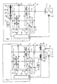
- Figur 1: Ein Schaltbild eines synchrongliederfreien Stufenwechselgetriebes mit einer Synchronisiervorrichtung, die an der der Kupplung abgewandten Seite des Getriebegehäuses angeordnet ist und deren Energieübertragungssystem durch eine Asynchronmaschine gebildet ist,
- Figur 2: Eine andere Ausführungsform des erfindungsgemäßen Stufenwechselgetriebes, bei dem das Energieübertragungssystem der Synchronisiervorrichtung aus einer Asynchronmaschine gebildet ist, deren Kurzschlußkäfigläufer auf der von der Antriebseinheit lösbaren Schwungmasse angeordnet ist.
- 1 shows a circuit diagram of a synchronous link-free step change transmission with a synchronizing device which is arranged on the side of the transmission housing facing away from the clutch and whose energy transmission system is formed by an asynchronous machine,
- Figure 2: Another embodiment of the step change transmission according to the invention, in which the energy transmission system of the synchronizing device is formed from an asynchronous machine, the squirrel-cage rotor of which is arranged on the flywheel that can be detached from the drive unit.
In den einzelnen Figuren der Zeichnung ist für jeweils gleiche Bauteile das gleiche Bezugszeichen verwendet worden.The same reference numerals have been used for the same components in the individual figures of the drawing.
In der Zeichnung der Figur 1 ist ein synchrongliederfreies Stufenwechselgetriebe 1 dargestellt, in dessen Getriebegehäuse 1′ im wesentlichen eine Getriebeeingangswelle 2 und eine Abtriebswelle 3 sowie eine Untersetzungsstufe 11 angeordnet sind. Die Getriebeeingangswelle 2 und die Abtriebswelle 3 sind über Zahnradpaare 4, 5, 6, 7 formschlüssig miteinander verbindbar. Antriebsseitig ist die Getriebeeingangswelle 2 des Stufenwechselgetriebes 1 über eine Kupplung 8 mit einer eine Schwungmasse 9 aufweisenden Antriebseinheit 10 verbunden. Der über eine Welle 12 erfolgende Abtrieb des Stufenwechselgetriebes 1 ist mit den in der Zeichnung nicht dargestellten Antriebsrädern des Fahrzeugs verbunden. Die Drehzahl der Abtriebswelle 3 wird durch einen Drehzahlsensor 13 erfaßt, der im Getriebegehäuse 1′ dem Zahnradpaar 7 zugeordnet ist. In gleicher Weise wird die Drehzahl der Getriebeeingangswelle 2 von einem Drehzahlsensor 14 erfaßt, der im Getriebegehäuse 1′ dem Zahnradpaar 5 zugeordnet ist. Die Drehzahlsensoren 13, 14 sind über Signalübertragungsleitungen mit einer Steuervorrichtung 15 verbunden. Diese Steuervorrichtung 15 ist darüber hinaus mit Betätigungsvorrichtungen 16 und 17 verbunden, die über Schiebemuffen 24 und 25 den Formschluß der jeweilig gewählten Getriebestufe ermöglichen. An der der Kupplung 8 abgewandten Seite des Getriebegehäuses 1′ ist ein als elektrische Maschine ausgebildetes Energieübertragungssystem 18 angeordnet. Die elektrische Maschine besteht dabei im wesentlichen aus einem Ständer 19a, einer Maschinensteuerungseinrichtung 19b und einem Kurzschlußkäfigläufer 20. Über die Maschinensteuerungseinrichtung 19b ist eine Energiespeichereinrichtung 21 mit der elektrischen Maschine 18 verbunden. Eine Signalleitung zwischen Maschinensteuerungseinrichtung 19b und Steuervorrichtung 15 ermöglicht die für den jeweiligen Schaltvorgang erforderliche Steuerung des Energieflusses zwischen Getriebeeingangswelle 2 und Energiespeichereinrichtung 21. Eine weitere Signalleitung verbindet die Steuervorrichtung 15 mit einer an der Antriebseinheit 10 angeordneten Drehzahlverstelleinrichtung 22.In the drawing of Figure 1, a synchronous link-free
Zur näheren Erläuterung des erfindungsgemäßen Stufenwechselgetriebes wird der Schaltvorgang vom zweiten in den dritten Getriebegang beispielhaft beschrieben. Zunächst wird die Verspannung des Antriebsstranges durch Öffnen der Kupplung 8 aufgehoben. Danach veranlaßt die Steuervorrichtung 15 über die Betätigungsvorrichtung 17 eine Bewegung der auf der Getriebeeingangswelle 2 drehfest angeordneten Schiebemuffe 25 in Pfeilrichtung A. Damit ist die formschlüssige Verbindung der Getriebeeingangswelle 2 mit der Abtriebswelle 3 aufgehoben. Die nun frei drehbare Getriebeeingangswelle 2 wird von der als Generator wirkenden elektrischen Maschine 18 so lange verzögert, bis die Drehzahl des Abtriebszahnrads in der Getriebestufe 5 mit der Drehzahl der auf der Abtriebswelle 3 drehfest angeordneten Schiebemuffe 24 nahezu übereinstimmt. Anschließend wird auf Veranlassung der Steuervorrichtung 15 die Schiebemuffe 24 durch die Betätigungsvorrichtung 16 in Pfeilrichtung B bewegt. Der Formschluß zwischen Getriebeeingangswelle 2 und Abtriebswelle 3 ist somit wieder hergestellt. Der Schaltvorgang wird beendet durch Schließen der Kupplung 8.For a more detailed explanation of the step change transmission according to the invention, the switching process from the second to the third gear is described by way of example. First, the tension in the drive train is released by opening the
Beim Herunterschalten vom dritten in den zweiten Getriebegang läuft der zuvor beschriebene Vorgang in umgekehrter Reihenfolge ab. Die frei bewegliche Getriebeeingangswelle 2 muß jedoch zur Synchronisierung beschleunigt werden. Diese Beschleunigung kann ebenfalls durch die elektrische Maschine 18 erreicht werden. Diese arbeitet dann wie ein elektrischer Antriebsmotor und bezieht ihre Energie aus einem Energiespeicher 21. Dieser Energiespeicher 21 ist so ausgebildet, daß er die beim Hochschalten während der Verzögerung der Getriebeeingangswelle 2 frei werdende Energie einspeichern kann. Darüber hinaus ist auch die Einspeicherung von zusätzlicher Energie denkbar, welche der Antriebseinheit 10 oder dem von der Abtriebswelle 3 bis zu den Antriebsrädern reichenden Abtriebsstrang entnommen wird.When shifting down from the third to the second gear, the process described above takes place in reverse order. However, the freely movable
Bei der Beendigung des Schaltvorganges kann ein für den Fahrzeuginsassen unangenehmes Rucken des gesamten Fahrzeuges auftreten, wenn vor dem Schließen der Kupplung 8 die Getriebeeingangswelle 2 und die Antriebseinheit 10 unterschiedliche Drehzahlen aufweisen. Für das erfindungsgemäße Ausführungsbeispiel ist deshalb eine Drehzahlverstellvorrichtung 22 an der Antriebseinheit 10 angeordnet, welche in Abhängigkeit von den Signalen der Steuervorrichtung 15 während des Synchronisiervorganges die Drehzahl der Antriebseinheit 10 an die Drehzahl der Getriebeeingangswelle 2 angleicht. Die während des Synchronisiervorganges beispielsweise in den Leerlauf zurückgefallene Antriebseinheit 10 müßte beschleunigt werden, um in etwa die im Augenblick der Synchronisation auftretende Drehzahl der Getriebeeingangswelle 2 zu erreichen. Die noch verbleibenden geringfügigen Drehzahldifferenezn zwischen Antriebseinheit 10 und Getriebeeingangswelle 2 werden während des Schließvorganges der Kupplung 8 aufgehoben. Auf diese Weise erhält man einen sehr gleichmäßigen Drehmomentenübergang und ermöglicht so einen Schaltvorgang mit Komfort.At the end of the switching process, an uncomfortable jerking of the entire vehicle can occur if the
Das in Figur 2 dargestellte Stufenwechselgetriebe 1 ist innerhalb des Getriebegehäuses 1′ in Aufbau und Funktion identisch mit dem in Figur 1 dargestellten Stufenwechselgetriebe. Die elekrische Maschine 18 ist hier jedoch zwischen der Antriebseinheit 10 und der Getriebeeingangswelle 2 angeordnet. Bei diesem erfindungsgemäßen Ausführungsbeispiel ist die Schwungmasse 9 von der Antriebseinheit 10 durch eine zweite Kupplung 23 lösbar. Der Läufer 20 der elektrischen Maschine 18 ist auf der Schwungmasse 9 angeordnet. Der Ständer 19a der elektrischen Maschine 18 ist an ortsfesten, die Schwungmasse 9 umgebenden Gehäuseteilen 1′ befestigt. Beim Hochschalten vom zweiten in den dritten Gang wird der Antriebsstrang zunächst durch Öffnen der zweiten Kupplung 23 unterbrochen, während die Kupplung 8 geschlossen bleibt. Der Formschluß zwischen Getriebeeingangswelle 2 und Abtriebswelle 3 wird durch Bewegung der Schiebemuffe 25 in Pfeilrichtung A aufgehoben. Damit ist das aus Getriebeeingangswelle 2, Kupplung 8 und Schwungmasse 9 bestehende System frei beweglich. Die beim Hochschalten erforderliche Verzögerung der Getriebeeingangswelle 2 kann nun von der als Generator wirkenden elektrischen Maschine 18 erreicht werden. Die dabei frei gewordene Energie wird dem Speicher 21 zugeführt, der beispielsweise als eine Batterie ausgebildet ist. Ist durch die Verzögerung der Getriebeeingangswelle 2 in etwa ein Gleichlauf zwischen der drehfest auf der Abtriebswelle 3 verschiebbaren Schiebemuffe 24 und dem Abtriebszahnrad der Zahnradstufe 5 erzielt worden, so erfolgt durch Verschieben der Schiebemuffe 24 in Pfeilrichtung B die Herstellung des Formschlusses zwischen Getriebeeingangswelle 2 und Abtriebswelle 3. Im Anschluß daran wird die zweite Kupplung 23 geschlossen, so daß die Antriebsleistung der Antriebseinheit 10 wieder auf die Antriebsräder übertragen werden kann. Die Kupplung 23 kann aber bei Formschluß zwischen Getriebeeingangswelle 2 und Abtriebswelle 3 auch geöffnet bleiben, wenn allein mit der elektrischen Maschine 18 Antriebsleistung erzeugt werden soll.The
Beim Herunterschalten vom dritten in den zweiten Gang verläuft der Schaltvorgang in umgekehrter Reihenfolge. Wie unter Figur 1 schon beschrieben, wird beim Herunterschalten jedoch eine Beschleunigung der Getriebeeingangswelle 2 notwendig. Die für die Beschleunigung notwendig werdende Energie entnimmt die elektrische Maschine 18 auch bei der in Figur 2 dargestellten Anordnung einem Energiespeicher 21. Bei geöffneter zweiter Kupplung 23 wird das aus Getriebeeingangswelle 2, Kupplung 8 und Schwungmasse 9 bestehende System bis zum Synchronlauf der formschlüssig miteinander zu verbindenden Getriebeglieder beschleunigt. Anschließend wird durch eine entsprechende Schiebemuffenbewegung und das Schließen der zweiten Kupplung 23 die Antriebsleistung der Antriebseinheit 10 wieder auf die Antriebsräder übertragen.When shifting down from third to second gear, the shifting process takes place in reverse order. As already described under FIG. 1, an acceleration of the
Das in Figur 2 dargestellte Ausführungsbeispiel des erfindungsgemäßen Stufenwechselgetriebes 1 ist in seinem prinzipiellen Aufbau mit bekannten Antriebsanordnungen für Elektrohybridfahrzeuge vergleichbar. Im Gegensatz zu diesen bisher bekannten Anordnungen ermöglicht die elektrische Maschine 18 bei dem erfindungsgemäßen Ausführungsbeispiel zusätzlich das synchrongliederfreie Schalten im Stufenwechselgetriebe 1. Damit wird ohne zusätzlichen konstruktiven Aufwand die Nutzung der elektrischen Maschine als Synchronisiervorrichtung möglich. Sie kann unabhängig von der Antriebseinheit sowohl die Beschleunigung als auch die Verzögerung der Getriebeeingangswelle 2 bewirken und ist von der ohnehin vorhandenen Steuervorrichtung 15 mit einfachen Mitteln steuerbar.The basic design of the exemplary embodiment of the
Analog zu dem in Figur 1 dargestellten Ausführungsbeispiel ist auch für das in Figur 2 dargestellte Ausführungsbeispiel ein gleichmäßiger Drehmomentenübergang zwischen der Antriebseinheit 10 und dem aus Getriebeeingangswelle 2, Kupplung 8 und Schwungmasse 9 bestehenden System über die Drehzahlverstellvorrichtung 22 möglich.Analogous to the exemplary embodiment shown in FIG. 1, a uniform torque transition between the
Claims (17)
Applications Claiming Priority (2)
| Application Number | Priority Date | Filing Date | Title |
|---|---|---|---|
| DE3814527 | 1988-04-29 | ||
| DE3814527 | 1988-04-29 |
Publications (3)
| Publication Number | Publication Date |
|---|---|
| EP0348622A2 true EP0348622A2 (en) | 1990-01-03 |
| EP0348622A3 EP0348622A3 (en) | 1990-07-04 |
| EP0348622B1 EP0348622B1 (en) | 1993-06-23 |
Family
ID=6353195
Family Applications (1)
| Application Number | Title | Priority Date | Filing Date |
|---|---|---|---|
| EP89107003A Expired - Lifetime EP0348622B1 (en) | 1988-04-29 | 1989-04-19 | Stepped shift transmission |
Country Status (2)
| Country | Link |
|---|---|
| EP (1) | EP0348622B1 (en) |
| DE (1) | DE58904778D1 (en) |
Cited By (22)
| Publication number | Priority date | Publication date | Assignee | Title |
|---|---|---|---|---|
| DE4122628A1 (en) * | 1991-07-09 | 1993-01-14 | Renk Ag | TRANSMISSION SYSTEM |
| EP0681118A1 (en) * | 1994-05-05 | 1995-11-08 | Eaton Corporation | Power synchronization for compound transmission |
| EP0690965A4 (en) * | 1994-01-31 | 1996-06-05 | Equipamentos Clark Ltda | Single sliding key type countershaft automatic transmission |
| DE19627895C1 (en) * | 1996-07-11 | 1998-02-19 | Daimler Benz Ag | Gear wheel variable gear |
| DE19652971A1 (en) * | 1996-12-19 | 1998-06-25 | Zahnradfabrik Friedrichshafen | Synchronised gearbox for commercial vehicles |
| WO1999057459A1 (en) * | 1998-05-05 | 1999-11-11 | Renault | Synchronised gearbox |
| FR2783587A1 (en) * | 1998-09-17 | 2000-03-24 | Bosch Gmbh Robert | METHOD AND DEVICE FOR A RETROGRADATION OPERATION OF A MOTOR VEHICLE GEARBOX |
| FR2784058A1 (en) * | 1998-10-02 | 2000-04-07 | Luk Getriebe Systeme Gmbh | GEARBOX, TYPE OF GEARS, WITH INTEGRATED ELECTRIC MACHINE. |
| DE19950679A1 (en) * | 1999-10-21 | 2001-04-26 | Volkswagen Ag | Automatic double clutch gearbox esp. for motor vehicle with at least two gearbox input shafts and gearbox driven shaft and unsynchronized gear changing couplings so that each of gearbox |
| WO2001004514A3 (en) * | 1999-07-08 | 2001-06-28 | Zahnradfabrik Friedrichshafen | Automated gear-shift system for a motor vehicle |
| EP1232891A1 (en) * | 2001-02-19 | 2002-08-21 | Peugeot Citroen Automobiles SA | Motion transmitting system for hybrid vehicles |
| EP1093552B1 (en) * | 1998-07-06 | 2003-08-27 | Scania CV Aktiebolag (publ) | Arrangement and method for a driving unit in a vehicle |
| US6634247B2 (en) * | 2000-07-18 | 2003-10-21 | Luk Lamellen Und Kupplungsbau Beteiligungs Kg | Double-clutch transmission |
| DE10243375A1 (en) * | 2002-05-22 | 2003-12-18 | Hitachi Ltd | transmission |
| FR2897134A1 (en) * | 2006-02-03 | 2007-08-10 | Renault Sas | HYBRID POWER UNIT OPTIMIZED FOR FIRST SPEED AND REVERSE ENGAGEMENT |
| WO2007141437A1 (en) * | 2006-06-08 | 2007-12-13 | Peugeot Citroen Automobiles Sa | Process and engagement system for a speed ratio, recording support for this process |
| FR2913474A1 (en) * | 2007-03-09 | 2008-09-12 | Peugeot Citroen Automobiles Sa | Gear ratio changing method for hybrid vehicle, involves forming traction chain by heat engine, clutch and gear box, and clutching final ratio to separate synchronizer from gear when gearbox is synchronized with rate of final ratio |
| DE102008040918A1 (en) * | 2008-08-01 | 2010-02-04 | Zf Friedrichshafen Ag | Transmission device for vehicle drive train, has electrical machine arranged to frictional switch element, where torque is presettable in region of control and regulating device actuating electrical machine and brake |
| DE102010028935A1 (en) * | 2010-05-12 | 2011-11-17 | Zf Friedrichshafen Ag | Method for operating drive train of motor vehicle i.e. hybrid vehicle, involves connecting friction clutch between electric machine and gearbox, and synchronizing transmission shaft of gearbox under utilization of rotor of electric machine |
| WO2015071563A1 (en) * | 2013-11-18 | 2015-05-21 | Peugeot Citroen Automobiles Sa | Method for controlling an alternator combined with a motor vehicle combustion engine |
| DE10119200B4 (en) * | 2000-04-21 | 2016-07-07 | Aisin Aw Co., Ltd. | Lock-up control device in an automatic transmission |
| EP3071464A4 (en) * | 2013-11-21 | 2017-07-19 | Scania CV AB | Method for controlling gear shifting in a hybrid driveline by use of an electric machine |
Families Citing this family (1)
| Publication number | Priority date | Publication date | Assignee | Title |
|---|---|---|---|---|
| DE10217746B4 (en) * | 2002-04-20 | 2005-06-16 | Zf Sachs Ag | Synchronizer for a manual transmission and corresponding motor vehicle drive train |
Family Cites Families (10)
| Publication number | Priority date | Publication date | Assignee | Title |
|---|---|---|---|---|
| DE1804533C3 (en) * | 1968-10-23 | 1974-02-14 | Ardie-Werk Gmbh, 8500 Nuernberg | Electro-hydraulic switching device for gear change transmissions |
| DE1941445C3 (en) * | 1969-08-14 | 1986-07-10 | Lahive Jun., John Anthony, Hingham, Mass. | Synchronization switching device for a gear change transmission of motor vehicles |
| IT939884B (en) * | 1971-09-25 | 1973-02-10 | Fiat Spa | AC ELECTRON SYNCHRONIZATION TRANSMISSION PARTICULARLY FOR AUTOMOBILES |
| GB1435517A (en) * | 1972-09-23 | 1976-05-12 | British Leyland Truck & Bus | Gearbox |
| DE2622927A1 (en) * | 1975-05-23 | 1976-12-09 | British Leyland Uk Ltd | Automatic transmission for heavy vehicle - with fluid clutch and sensors to control gear change without synchronisation |
| DE2622827C2 (en) * | 1976-05-21 | 1985-03-28 | Siemens AG, 1000 Berlin und 8000 München | Decoding circuit for secondary radar response signals |
| AT372654B (en) * | 1979-06-28 | 1983-11-10 | Steyr Daimler Puch Ag | ACTUATING DEVICE FOR THE CONTROL UNIT ASSIGNED TO THE INPUT SIDE OF A MOTOR VEHICLE INTERCHANGEABLE GEARBOX, THE BRAKE SERVING THE SWITCH EASIER |
| DE3021489A1 (en) * | 1980-06-07 | 1981-12-24 | Volkswagenwerk Ag, 3180 Wolfsburg | Synchronised automatic gear system for vehicle - switches in selected gear when two mating rotating parts have same speed |
| GB8430235D0 (en) * | 1984-11-30 | 1985-01-09 | Everton J M | Gearbox |
| DE8806211U1 (en) * | 1988-05-10 | 1988-06-30 | Klöckner-Humboldt-Deutz AG, 5000 Köln | Drive for a motor vehicle |
-
1989
- 1989-04-19 EP EP89107003A patent/EP0348622B1/en not_active Expired - Lifetime
- 1989-04-19 DE DE8989107003T patent/DE58904778D1/en not_active Expired - Lifetime
Cited By (37)
| Publication number | Priority date | Publication date | Assignee | Title |
|---|---|---|---|---|
| DE4122628A1 (en) * | 1991-07-09 | 1993-01-14 | Renk Ag | TRANSMISSION SYSTEM |
| US5992254A (en) * | 1994-01-31 | 1999-11-30 | Eaton Ltda | Gear-shifting mechanism controlled and commanded by a governing unit in an automatic controlled way |
| EP0690965A4 (en) * | 1994-01-31 | 1996-06-05 | Equipamentos Clark Ltda | Single sliding key type countershaft automatic transmission |
| CN1082155C (en) * | 1994-01-31 | 2002-04-03 | 伊顿汽车装配公司 | Transmission mechanism automatically controlled by the control device |
| EP0681118A1 (en) * | 1994-05-05 | 1995-11-08 | Eaton Corporation | Power synchronization for compound transmission |
| US5560249A (en) * | 1994-05-05 | 1996-10-01 | Eaton Corporation | Power synchronizer for a compound transmission |
| DE19627895C1 (en) * | 1996-07-11 | 1998-02-19 | Daimler Benz Ag | Gear wheel variable gear |
| DE19652971A1 (en) * | 1996-12-19 | 1998-06-25 | Zahnradfabrik Friedrichshafen | Synchronised gearbox for commercial vehicles |
| FR2778443A1 (en) * | 1998-05-05 | 1999-11-12 | Renault | SYNCHRONIZED GEARBOX |
| WO1999057459A1 (en) * | 1998-05-05 | 1999-11-11 | Renault | Synchronised gearbox |
| EP1093552B1 (en) * | 1998-07-06 | 2003-08-27 | Scania CV Aktiebolag (publ) | Arrangement and method for a driving unit in a vehicle |
| FR2783587A1 (en) * | 1998-09-17 | 2000-03-24 | Bosch Gmbh Robert | METHOD AND DEVICE FOR A RETROGRADATION OPERATION OF A MOTOR VEHICLE GEARBOX |
| GB2359865A (en) * | 1998-10-02 | 2001-09-05 | Luk Lamellen & Kupplungsbau | Transmission comprising at least two shafts and an electric motor or an automated clutch |
| WO2000020243A1 (en) * | 1998-10-02 | 2000-04-13 | Luk Lamellen Und Kupplungsbau Gmbh | Transmission comprising at least two shafts and an electric motor or an automated clutch |
| JP2002526326A (en) * | 1998-10-02 | 2002-08-20 | ルーク ラメレン ウント クツプルングスバウ ベタイリグングス コマンディートゲゼルシャフト | Transmission having at least two shafts and an electric machine or automatic disc clutch |
| US6506139B2 (en) | 1998-10-02 | 2003-01-14 | Luk Lamellen Und Kupplungsbau Beteiligungs Kg | Transmission with an electro-mechanical energy converter |
| GB2359865B (en) * | 1998-10-02 | 2003-07-23 | Luk Lamellen & Kupplungsbau | Transmission comprising at least two shafts and an electric motor |
| FR2784058A1 (en) * | 1998-10-02 | 2000-04-07 | Luk Getriebe Systeme Gmbh | GEARBOX, TYPE OF GEARS, WITH INTEGRATED ELECTRIC MACHINE. |
| WO2001004514A3 (en) * | 1999-07-08 | 2001-06-28 | Zahnradfabrik Friedrichshafen | Automated gear-shift system for a motor vehicle |
| DE19950679A1 (en) * | 1999-10-21 | 2001-04-26 | Volkswagen Ag | Automatic double clutch gearbox esp. for motor vehicle with at least two gearbox input shafts and gearbox driven shaft and unsynchronized gear changing couplings so that each of gearbox |
| DE19950679B4 (en) * | 1999-10-21 | 2010-01-07 | Volkswagen Ag | Automated dual-clutch transmission and method for controlling an automated dual-clutch transmission |
| DE10119200B4 (en) * | 2000-04-21 | 2016-07-07 | Aisin Aw Co., Ltd. | Lock-up control device in an automatic transmission |
| US6634247B2 (en) * | 2000-07-18 | 2003-10-21 | Luk Lamellen Und Kupplungsbau Beteiligungs Kg | Double-clutch transmission |
| FR2821137A1 (en) * | 2001-02-19 | 2002-08-23 | Peugeot Citroen Automobiles Sa | MOTION TRANSMISSION SYSTEM FOR HYBRID-DRIVEN VEHICLES |
| EP1232891A1 (en) * | 2001-02-19 | 2002-08-21 | Peugeot Citroen Automobiles SA | Motion transmitting system for hybrid vehicles |
| DE10243375A1 (en) * | 2002-05-22 | 2003-12-18 | Hitachi Ltd | transmission |
| FR2897134A1 (en) * | 2006-02-03 | 2007-08-10 | Renault Sas | HYBRID POWER UNIT OPTIMIZED FOR FIRST SPEED AND REVERSE ENGAGEMENT |
| WO2007141437A1 (en) * | 2006-06-08 | 2007-12-13 | Peugeot Citroen Automobiles Sa | Process and engagement system for a speed ratio, recording support for this process |
| FR2902168A1 (en) * | 2006-06-08 | 2007-12-14 | Peugeot Citroen Automobiles Sa | METHOD AND SYSTEM FOR ENGAGING A SPEED RATIO, RECORDING MEDIUM FOR THIS METHOD |
| FR2913474A1 (en) * | 2007-03-09 | 2008-09-12 | Peugeot Citroen Automobiles Sa | Gear ratio changing method for hybrid vehicle, involves forming traction chain by heat engine, clutch and gear box, and clutching final ratio to separate synchronizer from gear when gearbox is synchronized with rate of final ratio |
| DE102008040918A1 (en) * | 2008-08-01 | 2010-02-04 | Zf Friedrichshafen Ag | Transmission device for vehicle drive train, has electrical machine arranged to frictional switch element, where torque is presettable in region of control and regulating device actuating electrical machine and brake |
| DE102010028935A1 (en) * | 2010-05-12 | 2011-11-17 | Zf Friedrichshafen Ag | Method for operating drive train of motor vehicle i.e. hybrid vehicle, involves connecting friction clutch between electric machine and gearbox, and synchronizing transmission shaft of gearbox under utilization of rotor of electric machine |
| FR3013295A1 (en) * | 2013-11-18 | 2015-05-22 | Peugeot Citroen Automobiles Sa | METHOD FOR CONTROLLING AN ALTERNATOR ASSOCIATED WITH A THERMAL MOTOR OF A MOTOR VEHICLE |
| CN105745130A (en) * | 2013-11-18 | 2016-07-06 | 标致雪铁龙集团 | Method for controlling an alternator combined with a motor vehicle combustion engine |
| WO2015071563A1 (en) * | 2013-11-18 | 2015-05-21 | Peugeot Citroen Automobiles Sa | Method for controlling an alternator combined with a motor vehicle combustion engine |
| EP3071464A4 (en) * | 2013-11-21 | 2017-07-19 | Scania CV AB | Method for controlling gear shifting in a hybrid driveline by use of an electric machine |
| US9963151B2 (en) | 2013-11-21 | 2018-05-08 | Scania Cv Ab | Method for controlling gear shifting in a hybrid driveline by use of an electric machine |
Also Published As
| Publication number | Publication date |
|---|---|
| EP0348622B1 (en) | 1993-06-23 |
| DE58904778D1 (en) | 1993-07-29 |
| EP0348622A3 (en) | 1990-07-04 |
Similar Documents
| Publication | Publication Date | Title |
|---|---|---|
| EP0348622B1 (en) | Stepped shift transmission | |
| EP1127230B1 (en) | Gearbox for a motor vehicle, especially a gearbox with a dual clutch and method for operating said gearbox | |
| EP1126987B1 (en) | Hybrid transmission, especially for motor vehicles | |
| EP1610038B1 (en) | Double clutch transmission and control method of a double clutch transmission | |
| DE19619321C2 (en) | Method for operating a vehicle with several electric drive machines | |
| EP0262625B1 (en) | Process for shifting the gears of a transmission consisting of several components | |
| EP0088150B1 (en) | Mechanical transmission arrangement shiftable under load | |
| DE19903936A1 (en) | Gearboxes, in particular for motor vehicles | |
| EP1280677A2 (en) | Hybrid transmission, particularly for motor vehicles | |
| EP1714817A1 (en) | Hybrid drive system with double clutch | |
| DE10136725A1 (en) | Transmission system for hybrid vehicle with gearbox, automatic gear controller and electric motor, varies motor speed in accordance with gear selection | |
| DE19954544A1 (en) | Driving mechanism for applying to a motor vehicle drives two equal vehicle wheels with a travelling gear engine and two electrical motors separated from shaft connections connecting a balancing gear mechanism to the wheels. | |
| DE2406076A1 (en) | GEAR GEAR WITH DEVICES FOR PLAY ADJUSTMENT | |
| DE102008001650A1 (en) | Drive strand arrangement for vehicle i.e. commercial motor vehicle, has auxiliary transmission arranged downstream to main gear and coupled with mechanism i.e. electric machine, for applying support moment on mechanism | |
| EP3096995A1 (en) | Device for driving at least one output shaft of a rail vehicle and method for operating such a device | |
| DE102019211678A1 (en) | Propulsion system and method for operating a propulsion system | |
| DE102017222705B4 (en) | Transmission for a motor vehicle | |
| EP0348732B1 (en) | Rotational-speed synchronisation method | |
| DE102017222717B4 (en) | Transmission for a motor vehicle | |
| EP0868618B1 (en) | Method of controlling a power distribution hydromechanical branched transmission in uncertain gear positions | |
| DE102017202484B4 (en) | Drive device for a motor vehicle with an auxiliary drive that can be driven via a gear change gear controlled by means of a centrifugal actuator, and a method for operating such a drive device | |
| DE4226665C2 (en) | Device for the integral control of an internal combustion engine, in particular a diesel engine, and a mechanical gearbox during a gearshift operation in a drive train for a rail vehicle | |
| DE102014219099A1 (en) | Method for switching control of an automated manual transmission in an electric motor driven vehicle | |
| DE102014204437A1 (en) | Gear arrangement and transmission for a motor vehicle and method for operating a gear assembly | |
| WO2020048712A1 (en) | Transmission for a motor vehicle, motor vehicle powertrain, and method for operating a transmission |
Legal Events
| Date | Code | Title | Description |
|---|---|---|---|
| PUAI | Public reference made under article 153(3) epc to a published international application that has entered the european phase |
Free format text: ORIGINAL CODE: 0009012 |
|
| AK | Designated contracting states |
Kind code of ref document: A2 Designated state(s): DE FR GB IT |
|
| PUAL | Search report despatched |
Free format text: ORIGINAL CODE: 0009013 |
|
| AK | Designated contracting states |
Kind code of ref document: A3 Designated state(s): DE FR GB IT |
|
| 17P | Request for examination filed |
Effective date: 19900531 |
|
| 17Q | First examination report despatched |
Effective date: 19920625 |
|
| GRAA | (expected) grant |
Free format text: ORIGINAL CODE: 0009210 |
|
| AK | Designated contracting states |
Kind code of ref document: B1 Designated state(s): DE FR GB IT |
|
| REF | Corresponds to: |
Ref document number: 58904778 Country of ref document: DE Date of ref document: 19930729 |
|
| ET | Fr: translation filed | ||
| ITF | It: translation for a ep patent filed | ||
| GBT | Gb: translation of ep patent filed (gb section 77(6)(a)/1977) |
Effective date: 19930923 |
|
| PLBE | No opposition filed within time limit |
Free format text: ORIGINAL CODE: 0009261 |
|
| STAA | Information on the status of an ep patent application or granted ep patent |
Free format text: STATUS: NO OPPOSITION FILED WITHIN TIME LIMIT |
|
| 26N | No opposition filed | ||
| PGFP | Annual fee paid to national office [announced via postgrant information from national office to epo] |
Ref country code: GB Payment date: 20000410 Year of fee payment: 12 |
|
| PGFP | Annual fee paid to national office [announced via postgrant information from national office to epo] |
Ref country code: FR Payment date: 20000420 Year of fee payment: 12 |
|
| PG25 | Lapsed in a contracting state [announced via postgrant information from national office to epo] |
Ref country code: GB Free format text: LAPSE BECAUSE OF NON-PAYMENT OF DUE FEES Effective date: 20010419 |
|
| PG25 | Lapsed in a contracting state [announced via postgrant information from national office to epo] |
Ref country code: FR Free format text: THE PATENT HAS BEEN ANNULLED BY A DECISION OF A NATIONAL AUTHORITY Effective date: 20010430 |
|
| GBPC | Gb: european patent ceased through non-payment of renewal fee |
Effective date: 20010419 |
|
| REG | Reference to a national code |
Ref country code: FR Ref legal event code: ST |
|
| PG25 | Lapsed in a contracting state [announced via postgrant information from national office to epo] |
Ref country code: IT Free format text: LAPSE BECAUSE OF NON-PAYMENT OF DUE FEES;WARNING: LAPSES OF ITALIAN PATENTS WITH EFFECTIVE DATE BEFORE 2007 MAY HAVE OCCURRED AT ANY TIME BEFORE 2007. THE CORRECT EFFECTIVE DATE MAY BE DIFFERENT FROM THE ONE RECORDED. Effective date: 20050419 |
|
| PGFP | Annual fee paid to national office [announced via postgrant information from national office to epo] |
Ref country code: DE Payment date: 20080430 Year of fee payment: 20 |