EP0348567A1 - Kupplungs- und Dichtungsvorrichtung - Google Patents
Kupplungs- und Dichtungsvorrichtung Download PDFInfo
- Publication number
- EP0348567A1 EP0348567A1 EP88305931A EP88305931A EP0348567A1 EP 0348567 A1 EP0348567 A1 EP 0348567A1 EP 88305931 A EP88305931 A EP 88305931A EP 88305931 A EP88305931 A EP 88305931A EP 0348567 A1 EP0348567 A1 EP 0348567A1
- Authority
- EP
- European Patent Office
- Prior art keywords
- cylinder
- plunger
- annular
- receiving
- seal
- Prior art date
- Legal status (The legal status is an assumption and is not a legal conclusion. Google has not performed a legal analysis and makes no representation as to the accuracy of the status listed.)
- Withdrawn
Links
- 230000008878 coupling Effects 0.000 title claims abstract description 12
- 238000010168 coupling process Methods 0.000 title claims abstract description 12
- 238000005859 coupling reaction Methods 0.000 title claims abstract description 12
- 238000007789 sealing Methods 0.000 claims abstract description 7
- 239000007788 liquid Substances 0.000 claims description 12
- 230000004323 axial length Effects 0.000 claims description 2
- 230000002093 peripheral effect Effects 0.000 claims 1
- 230000000712 assembly Effects 0.000 description 3
- 238000000429 assembly Methods 0.000 description 3
- 238000010276 construction Methods 0.000 description 1
- 238000006073 displacement reaction Methods 0.000 description 1
- 230000000694 effects Effects 0.000 description 1
- 239000012530 fluid Substances 0.000 description 1
- 238000004519 manufacturing process Methods 0.000 description 1
- 238000000034 method Methods 0.000 description 1
- 239000000126 substance Substances 0.000 description 1
Images
Classifications
-
- F—MECHANICAL ENGINEERING; LIGHTING; HEATING; WEAPONS; BLASTING
- F16—ENGINEERING ELEMENTS AND UNITS; GENERAL MEASURES FOR PRODUCING AND MAINTAINING EFFECTIVE FUNCTIONING OF MACHINES OR INSTALLATIONS; THERMAL INSULATION IN GENERAL
- F16J—PISTONS; CYLINDERS; SEALINGS
- F16J1/00—Pistons; Trunk pistons; Plungers
- F16J1/10—Connection to driving members
- F16J1/12—Connection to driving members with piston-rods, e.g. rigid connections
-
- F—MECHANICAL ENGINEERING; LIGHTING; HEATING; WEAPONS; BLASTING
- F04—POSITIVE - DISPLACEMENT MACHINES FOR LIQUIDS; PUMPS FOR LIQUIDS OR ELASTIC FLUIDS
- F04B—POSITIVE-DISPLACEMENT MACHINES FOR LIQUIDS; PUMPS
- F04B53/00—Component parts, details or accessories not provided for in, or of interest apart from, groups F04B1/00 - F04B23/00 or F04B39/00 - F04B47/00
- F04B53/14—Pistons, piston-rods or piston-rod connections
- F04B53/144—Adaptation of piston-rods
- F04B53/147—Mounting or detaching of piston rod
-
- F—MECHANICAL ENGINEERING; LIGHTING; HEATING; WEAPONS; BLASTING
- F16—ENGINEERING ELEMENTS AND UNITS; GENERAL MEASURES FOR PRODUCING AND MAINTAINING EFFECTIVE FUNCTIONING OF MACHINES OR INSTALLATIONS; THERMAL INSULATION IN GENERAL
- F16B—DEVICES FOR FASTENING OR SECURING CONSTRUCTIONAL ELEMENTS OR MACHINE PARTS TOGETHER, e.g. NAILS, BOLTS, CIRCLIPS, CLAMPS, CLIPS OR WEDGES; JOINTS OR JOINTING
- F16B2200/00—Constructional details of connections not covered for in other groups of this subclass
- F16B2200/40—Clamping arrangements where clamping parts are received in recesses of elements to be connected
- F16B2200/406—Clamping parts being collars, bushings or wedges
-
- Y—GENERAL TAGGING OF NEW TECHNOLOGICAL DEVELOPMENTS; GENERAL TAGGING OF CROSS-SECTIONAL TECHNOLOGIES SPANNING OVER SEVERAL SECTIONS OF THE IPC; TECHNICAL SUBJECTS COVERED BY FORMER USPC CROSS-REFERENCE ART COLLECTIONS [XRACs] AND DIGESTS
- Y10—TECHNICAL SUBJECTS COVERED BY FORMER USPC
- Y10T—TECHNICAL SUBJECTS COVERED BY FORMER US CLASSIFICATION
- Y10T403/00—Joints and connections
- Y10T403/60—Biased catch or latch
Definitions
- This invention relates to a coupling and seal assembly.
- Known coupling and seal assemblies such as are used in high-pressure, liquid intensifiers, for instance, present laborious assembly and disassembly procedures, and are expensive of manufacture.
- Such assemblies comprise bolting; the bolts are subject to fretting, damaging over-torquing, or dangerous under-torquing, and are exposed to the liquid and, consequently, accrete chemical deposits and become quite difficult to remove. Too, the practice of bolting these assemblies, of course, requires tapped holes in receiving components, and this is unduly expensive, requires correct alignment of bolted elements on assembly (or reassembly), and diminishes the structural integrity of the tapped, receiving components.
- a coupling and seal assembly for use in a high-pressure, liquid intensifier, or the like, comprising: a cylinder; means at one end of said cylinder for admitting pressured liquid into said cylinder; a plunger; a ram; means, engaging both said ram and a first end of said plunger, removably coupling said ram to said first end of said plunger; and apertured means, in the other end of said cylinder, (a) slidably receiving said plunger therewithin, and (b) centering said plunger in said cylinder; wherein said receiving and centering means includes means for sealing said cylinder against leakage of liquid therefrom via said other end thereof; and further including means securing said receiving and centering means in said cylinder against removal thereof via said other end; said securing means being but a single retaining ring; characterised in that said sealing means comprises an annular seal sealingly engaged with a second end of said plunger and with said cylinder; said receiving and centering means further includes
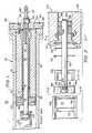
- a known high-pressure cylinder assembly 10 comprises a casing 12 in which is confined a high-pressure cylinder 14.
- the cylinder 14 confines a plunger 16 therewithin, and plunger/cylinder sealing elements 18.
- a ram 20 is removably coupled to the headed, extended end 22 of the plunger 16.
- the outermost end 24 of the cylinder 14 abuts an end plate 26 which is secured to the cylinder 14 by bolts 28 (only one is shown), and secured to the casing 12 by bolts 30.
- the coupling and seal assembly 32 of this known arrangement is generally encompassed by the bracketed portion shown in Figure 1. It can be noted that an end cap 34 is fastened to the inner end 36 of the cylinder 14 by bolts 38 (only one is shown). Consequently, the end 36 of the cylinder 14 has had to have a plurality of tapped holes 40 formed therein, and the end cap 34 has a corresponding number of bolt holes 42 formed therein.
- a conduit 44 for high-pressure liquid has a head portion 46 which is captive in the cylinder 14 and extends beyond the cylinder 14 with a threaded, terminal end 48.
- a bolt 50 secures the end 48 fast in the plate 26.
- Coupling and seal assembly 52 shown in Figures 2 to 4 comprises a high-pressure cylinder 54, a plunger 56 and a ram 58.
- An end 60 of the plunger 56 has a cleft-shaped, annular groove 62 formed therein.
- a collar of two pieces 64 and 64a is fitted to plunger end 60; each piece 64 and 64a has an inwardly-directed, arcuate ridge 66, and the latter engage the groove 62 to close the collar about the plunger and 60.
- a cup-shaped, centrally bored, collar retainer 68 slidably fits about the collared end of the plunger and, in turn, is snugly received in the thereadjacent end of the ram 58.
- the aforesaid end of the ram 58 has a cylindrical pocket 70 formed therein with an annular, inwardly-extending wall 72. Adjacent an outer end thereof, the pocket 70 has an annular groove 74 formed in an inner surface thereof. The wall 72 and groove 74 are spaced apart a given dimension, and the collar retainer 68 has a depth, or axial length "D" which is substantially the same given dimension. A retaining ring 76 is received in the groove 74, to secure the collar 64, 64a and collar retainer 68 in the pocket 70. The aforesaid substantially same dimensions, and wall 72 and ring 76, provide for a snug reception and fit of retainer 68 (and collar 64, 64a) in the pocket 70.
- a series of components which serve to receive and centre the working end 78 of the plunger 56, and to seal the cylinder against leakage of fluid therefrom.
- the innermost component is a seal 80 which sealingly engages the wall of the cylinder 54 and the outside-diameter surface of the plunger 56.
- Seal 80 is set against a seal seat 82.
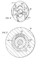
- the seat 82 abuts a key-positioning sleeve 84, and a three-piece key 86 which nests in an annular keyway 87 formed in the cylinder 54.
- the cylinder 54 has an annular shoulder 88 formed therein adjacent to the end thereof, and the sleeve 84 has an outwardly-extending flange 90 which sets into the shoulder 88. Finally, the cylinder 54 also has an inner, circumferential groove 92 in which is received a resilient retaining ring 94. The latter secures the sleeve 84 in place, and the outer surface of the sleeve 84 comprises a land which slidably receives and radially positions the three piece key 86.
- the key 86 has two, mirror-imaged pieces 86a and 86b; the third piece 86c is the smaller, and is of outwardly-diverging configuration.
- ring 94 is removed from groove 92 to permit removal of the sleeve 84 and the key pieces 86a, 86b and 86c.
- liquid is admitted into the cylinder 54 to fill it, and the plunger 56 is thrust thereinto. Displacement of the liquid by the plunger 56 forces the seal 80 and seat 82 to remove from the cylinder.
Landscapes
- Engineering & Computer Science (AREA)
- General Engineering & Computer Science (AREA)
- Mechanical Engineering (AREA)
- Chemical & Material Sciences (AREA)
- Combustion & Propulsion (AREA)
- Pistons, Piston Rings, And Cylinders (AREA)
Applications Claiming Priority (1)
| Application Number | Priority Date | Filing Date | Title |
|---|---|---|---|
| US07/053,773 US4757751A (en) | 1987-05-26 | 1987-05-26 | Ram couling and cylinder end seal assembly for high pressure cylinder |
Publications (1)
| Publication Number | Publication Date |
|---|---|
| EP0348567A1 true EP0348567A1 (de) | 1990-01-03 |
Family
ID=21986430
Family Applications (1)
| Application Number | Title | Priority Date | Filing Date |
|---|---|---|---|
| EP88305931A Withdrawn EP0348567A1 (de) | 1987-05-26 | 1988-06-27 | Kupplungs- und Dichtungsvorrichtung |
Country Status (2)
| Country | Link |
|---|---|
| US (1) | US4757751A (de) |
| EP (1) | EP0348567A1 (de) |
Cited By (2)
| Publication number | Priority date | Publication date | Assignee | Title |
|---|---|---|---|---|
| FR2711746A1 (fr) * | 1993-10-26 | 1995-05-05 | Bk Cie Francaise | Système d'accrochage d'une tige de vérin sur un collier. |
| EP0877164A3 (de) * | 1997-05-09 | 1999-08-11 | Genus Corporation | Hochdruckverdrängerpumpe |
Families Citing this family (17)
| Publication number | Priority date | Publication date | Assignee | Title |
|---|---|---|---|---|
| US4926745A (en) * | 1988-04-21 | 1990-05-22 | The United States Of Amerca As Represented By The United States Department Of Energy | Pull rod assembly |
| US5107569A (en) * | 1990-06-07 | 1992-04-28 | Daniel Hughes | Two-piece sun visor bushing and method of use |
| US5127764A (en) * | 1991-04-24 | 1992-07-07 | Shop Vac Corporation | Clip ring spread preventer |
| US5353805A (en) * | 1993-12-14 | 1994-10-11 | Mojena Gregory L | Aid for use by women in discharge of bodily wastes |
| US5622098A (en) * | 1996-03-08 | 1997-04-22 | Amalga Composites, Inc. | High pressure cylinder with locking end caps |
| ITTO980181A1 (it) * | 1998-03-05 | 1999-09-05 | Eltek Spa | Attuatore di tipo termico e metodo di chiusura e tenuta per il corpo di un attuatore di tipo termico. |
| IT1299758B1 (it) * | 1998-03-20 | 2000-04-04 | Scaglia Spa | Dispositivo per agganciare automaticamente un albero porta bobina ad un mandrino di una macchina |
| US6805024B1 (en) * | 2001-10-09 | 2004-10-19 | Valeo Electrical Systems, Inc. | End play restriction wedge |
| CN1300491C (zh) * | 2003-03-13 | 2007-02-14 | 上海交通大学 | 柱塞式高电压绝缘油缸 |
| US20040200840A1 (en) * | 2003-04-11 | 2004-10-14 | Stephen Oser | End closure assembly for a pressure vessel |
| US7240606B2 (en) * | 2004-07-15 | 2007-07-10 | Parker-Hannifin Corporation | Crimped piston to rod joint |
| US20100253005A1 (en) * | 2009-04-03 | 2010-10-07 | Liarakos Nicholas P | Seal for oil-free rotary displacement compressor |
| EP3193014B1 (de) * | 2016-01-12 | 2024-07-31 | Graco Minnesota Inc. | Kolbenstange mit kappenaussparung |
| US11554461B1 (en) | 2018-02-13 | 2023-01-17 | Omax Corporation | Articulating apparatus of a waterjet system and related technology |
| US12403621B2 (en) | 2019-12-20 | 2025-09-02 | Hypertherm, Inc. | Motorized systems and associated methods for controlling an adjustable dump orifice on a liquid jet cutting system |
| CN111894845B (zh) * | 2020-07-17 | 2022-02-22 | 重庆海浦洛自动化科技有限公司 | 一种汽车涂装供胶伺服定量机用密封机构及其拆装方法 |
| CN114076091A (zh) * | 2020-08-20 | 2022-02-22 | 苏州鼎元电源科技有限公司 | 一种碱性干电池加工的海霸泵柱塞机构 |
Citations (4)
| Publication number | Priority date | Publication date | Assignee | Title |
|---|---|---|---|---|
| US3175474A (en) * | 1960-05-17 | 1965-03-30 | Eickmann Karl | Closure device for hydraulic cylinder or the like |
| DE2032434A1 (de) * | 1969-06-30 | 1971-01-07 | Maschinenfabrik Burckhardt Ag, Basel (Schweiz) | Einrichtung zur zentrischen Fuhrung eines Kolbens in einem Arbeitszylinder von Hochdruck Kompressoren oder Pumpen |
| US3807285A (en) * | 1972-04-17 | 1974-04-30 | Cessna Aircraft Co | Connection between rod and piston of fluid power cylinder |
| FR2422847A1 (fr) * | 1978-04-14 | 1979-11-09 | Case Co J I | Ensemble de verin muni d'un organe de retenue a bague en plusieurs parties |
Family Cites Families (14)
| Publication number | Priority date | Publication date | Assignee | Title |
|---|---|---|---|---|
| US2690939A (en) * | 1950-12-20 | 1954-10-05 | Westinghouse Air Brake Co | Fluid pressure cylinder |
| US3136230A (en) * | 1963-09-30 | 1964-06-09 | Prince Mfg Corp | Hydraulic cylinder |
| US3627361A (en) * | 1967-06-14 | 1971-12-14 | Charles W Bimba | Fluid motor with a removably locked piston rod connection means |
| DE1907873C3 (de) * | 1969-02-17 | 1975-04-10 | Alfred Teves Gmbh, 6000 Frankfurt | Radbremszylinder für Teilbelagscheibenbremsen |
| US3722374A (en) * | 1971-06-14 | 1973-03-27 | R Densmore | Segmented retaining ring assembly |
| US3951048A (en) * | 1973-01-26 | 1976-04-20 | Clark Equipment Company | Piston and rod connection |
| IT1046312B (it) * | 1973-06-07 | 1980-06-30 | Pumpenfabrik Urach | Tenuta stagna di parti di macchina a moto di va e vieni |
| GB1509544A (en) * | 1974-12-18 | 1978-05-04 | Dobson Park Ind | Gland seal arrangements |
| US4182578A (en) * | 1978-03-24 | 1980-01-08 | Caterpillar Tractor Co. | Keeper assembly |
| US4324171A (en) * | 1978-06-16 | 1982-04-13 | Clark Equipment Company | Fluid device and method for making |
| NZ202076A (en) * | 1982-10-04 | 1986-06-11 | Campion & Irving Ltd | Retention of first member in bore of second member using grooves and retaining rings |
| US4476772A (en) * | 1982-11-04 | 1984-10-16 | Corbett Elevator Manufacturing Co., Inc. | Caging seal for hydraulic elevator or the like |
| DE3246349A1 (de) * | 1982-12-15 | 1984-06-20 | FAG Kugelfischer Georg Schäfer KGaA, 8720 Schweinfurt | Geberzylinder |
| JPS59151762U (ja) * | 1983-03-31 | 1984-10-11 | アイシン精機株式会社 | マスタシリンダ用シ−ル部材 |
-
1987
- 1987-05-26 US US07/053,773 patent/US4757751A/en not_active Expired - Fee Related
-
1988
- 1988-06-27 EP EP88305931A patent/EP0348567A1/de not_active Withdrawn
Patent Citations (4)
| Publication number | Priority date | Publication date | Assignee | Title |
|---|---|---|---|---|
| US3175474A (en) * | 1960-05-17 | 1965-03-30 | Eickmann Karl | Closure device for hydraulic cylinder or the like |
| DE2032434A1 (de) * | 1969-06-30 | 1971-01-07 | Maschinenfabrik Burckhardt Ag, Basel (Schweiz) | Einrichtung zur zentrischen Fuhrung eines Kolbens in einem Arbeitszylinder von Hochdruck Kompressoren oder Pumpen |
| US3807285A (en) * | 1972-04-17 | 1974-04-30 | Cessna Aircraft Co | Connection between rod and piston of fluid power cylinder |
| FR2422847A1 (fr) * | 1978-04-14 | 1979-11-09 | Case Co J I | Ensemble de verin muni d'un organe de retenue a bague en plusieurs parties |
Cited By (3)
| Publication number | Priority date | Publication date | Assignee | Title |
|---|---|---|---|---|
| FR2711746A1 (fr) * | 1993-10-26 | 1995-05-05 | Bk Cie Francaise | Système d'accrochage d'une tige de vérin sur un collier. |
| EP0877164A3 (de) * | 1997-05-09 | 1999-08-11 | Genus Corporation | Hochdruckverdrängerpumpe |
| US6171070B1 (en) * | 1997-05-09 | 2001-01-09 | Hakusu Tech Co., Ltd. | High-pressure reciprocating pumps |
Also Published As
| Publication number | Publication date |
|---|---|
| US4757751A (en) | 1988-07-19 |
Similar Documents
| Publication | Publication Date | Title |
|---|---|---|
| EP0348567A1 (de) | Kupplungs- und Dichtungsvorrichtung | |
| AU671778B2 (en) | Injector assembly | |
| US5171025A (en) | Sealing arrangement for a valve and more particularly one in the form of a multi-way valve | |
| CA1207658A (en) | Marine riser coupling assembly | |
| US4693497A (en) | Collet connector | |
| US4852611A (en) | Wellhead connection of hydraulic control lines | |
| US6923476B2 (en) | Floating seal for undersea hydraulic coupling | |
| GB2162271B (en) | Pipe coupling | |
| US4826180A (en) | Valve stem sealing assembly | |
| GB2230835A (en) | Pipe flange connections | |
| GB1573363A (en) | Device for the tensile locking of pipe sections | |
| IE43266B1 (en) | Pipe coupling | |
| US4572551A (en) | Fluid connector | |
| EP0234722B1 (de) | Verbunddichtung zwischen ebenen Flächen | |
| AU675584B2 (en) | Pipe connector | |
| GB2155577A (en) | Pipe clamps/connectors | |
| US4109940A (en) | Coupling apparatus | |
| US6418912B1 (en) | HPDI injector and packaging | |
| US4465097A (en) | Coupling | |
| AP1630A (en) | Pipe coupling. | |
| CN213871610U (zh) | 一种快速连接装置 | |
| AU2004257931A2 (en) | A hydraulic coupling device and a valve device provided with a sealing member | |
| JPH03502595A (ja) | 簡潔流体操作式装置及び方法 | |
| CA1287786C (en) | Coupling and seal assembly | |
| US4766934A (en) | Closure head for a hydraulic tube-testing bench |
Legal Events
| Date | Code | Title | Description |
|---|---|---|---|
| PUAI | Public reference made under article 153(3) epc to a published international application that has entered the european phase |
Free format text: ORIGINAL CODE: 0009012 |
|
| AK | Designated contracting states |
Kind code of ref document: A1 Designated state(s): DE FR GB IT NL SE |
|
| 17P | Request for examination filed |
Effective date: 19900409 |
|
| 17Q | First examination report despatched |
Effective date: 19910627 |
|
| STAA | Information on the status of an ep patent application or granted ep patent |
Free format text: STATUS: THE APPLICATION IS DEEMED TO BE WITHDRAWN |
|
| 18D | Application deemed to be withdrawn |
Effective date: 19911108 |