EP0348451B1 - Heisse gase führende leitung für eine brennkraftmaschine - Google Patents
Heisse gase führende leitung für eine brennkraftmaschine Download PDFInfo
- Publication number
- EP0348451B1 EP0348451B1 EP88909511A EP88909511A EP0348451B1 EP 0348451 B1 EP0348451 B1 EP 0348451B1 EP 88909511 A EP88909511 A EP 88909511A EP 88909511 A EP88909511 A EP 88909511A EP 0348451 B1 EP0348451 B1 EP 0348451B1
- Authority
- EP
- European Patent Office
- Prior art keywords
- line
- screws
- pipe
- exhaust duct
- hot
- Prior art date
- Legal status (The legal status is an assumption and is not a legal conclusion. Google has not performed a legal analysis and makes no representation as to the accuracy of the status listed.)
- Expired - Lifetime
Links
Images

Classifications
-
- F—MECHANICAL ENGINEERING; LIGHTING; HEATING; WEAPONS; BLASTING
- F02—COMBUSTION ENGINES; HOT-GAS OR COMBUSTION-PRODUCT ENGINE PLANTS
- F02F—CYLINDERS, PISTONS OR CASINGS, FOR COMBUSTION ENGINES; ARRANGEMENTS OF SEALINGS IN COMBUSTION ENGINES
- F02F1/00—Cylinders; Cylinder heads
- F02F1/24—Cylinder heads
- F02F1/42—Shape or arrangement of intake or exhaust channels in cylinder heads
- F02F1/4264—Shape or arrangement of intake or exhaust channels in cylinder heads of exhaust channels
- F02F1/4271—Shape or arrangement of intake or exhaust channels in cylinder heads of exhaust channels with an exhaust liner
-
- F—MECHANICAL ENGINEERING; LIGHTING; HEATING; WEAPONS; BLASTING
- F01—MACHINES OR ENGINES IN GENERAL; ENGINE PLANTS IN GENERAL; STEAM ENGINES
- F01N—GAS-FLOW SILENCERS OR EXHAUST APPARATUS FOR MACHINES OR ENGINES IN GENERAL; GAS-FLOW SILENCERS OR EXHAUST APPARATUS FOR INTERNAL-COMBUSTION ENGINES
- F01N13/00—Exhaust or silencing apparatus characterised by constructional features
- F01N13/14—Exhaust or silencing apparatus characterised by constructional features having thermal insulation
-
- F—MECHANICAL ENGINEERING; LIGHTING; HEATING; WEAPONS; BLASTING
- F02—COMBUSTION ENGINES; HOT-GAS OR COMBUSTION-PRODUCT ENGINE PLANTS
- F02F—CYLINDERS, PISTONS OR CASINGS, FOR COMBUSTION ENGINES; ARRANGEMENTS OF SEALINGS IN COMBUSTION ENGINES
- F02F1/00—Cylinders; Cylinder heads
- F02F1/24—Cylinder heads
- F02F2001/244—Arrangement of valve stems in cylinder heads
- F02F2001/247—Arrangement of valve stems in cylinder heads the valve stems being orientated in parallel with the cylinder axis
-
- F—MECHANICAL ENGINEERING; LIGHTING; HEATING; WEAPONS; BLASTING
- F02—COMBUSTION ENGINES; HOT-GAS OR COMBUSTION-PRODUCT ENGINE PLANTS
- F02F—CYLINDERS, PISTONS OR CASINGS, FOR COMBUSTION ENGINES; ARRANGEMENTS OF SEALINGS IN COMBUSTION ENGINES
- F02F1/00—Cylinders; Cylinder heads
- F02F1/24—Cylinder heads
- F02F1/42—Shape or arrangement of intake or exhaust channels in cylinder heads
- F02F1/4264—Shape or arrangement of intake or exhaust channels in cylinder heads of exhaust channels
- F02F2001/4278—Exhaust collectors
Definitions
- the invention relates to a hot gas line for an internal combustion engine according to the preamble of claim 1. Such an arrangement prevents the hot gas from coming into direct contact with the liquid-cooled envelope, thereby keeping the heat flow into the coolant small.
- a generic arrangement of a hot gas-carrying line is known from DE-GM 80 13 256.
- Several flange-like lugs are distributed over the length on each long side of the thin-walled line and lie against a corresponding flange surface of the liquid-cooled jacket.
- the cable is fastened using screws inserted perpendicular to the flange surface.
- the high temperatures of the hot gases that occur during operation lead to considerable differences in thermal expansion between the pipe and the jacket, which are only partially compensated for by the fastening.
- Thermal expansion that cannot be compensated leads to pressure forces that result in incalculable material stresses.
- the effects of the pressure forces overlap with the operational stresses of an internal combustion engine, such as vibration and gas pulsation, to the operational stresses of the pipeline.
- the advantages achieved by the invention consist in particular in that the generation of the line deformation necessarily takes place with the assembly of the fastening means, that the fastening means can be checked from the outside, that the undersize which results in the deformation of the line can be clearly measured during assembly, that there is an inexpensive manufacture of the line fastening.
- a line 11 which receives the hot exhaust gases of the exhaust gas turbine 12 (FIGS. 1 and 2).
- the thin-walled line 11 is surrounded by a liquid-cooled jacket 13 to which the line 11 and the exhaust line 14 are attached.
- the connection between line 11 and sheathing 13 takes place at the outlet end 15 of line 11 by means of four screws 16 arranged radially and in a cross-sectional plane.
- the wall of line 11 is equipped in the cross-sectional plane in accordance with the circumferential distribution of screws 16 with lenticular knobs 17, each of which have the corresponding nut thread 16.
- the line 11 In the initial state of assembly, when the line 11 is inserted into the casing 13, the line 11 has a radial undersize in the region of each lug 17. Due to the screws 16 engaging and tightening in the nut threads of the knobs 17, the line 11 is drawn against the sheathing, deforming its cross-sectional contour in the region of each knobs 17. The original radial undersize is then no longer available. For this purpose, the line 11 is deformed in the cross-sectional plane of the screws 16 in the wall sections between the lugs 17 to the contour shown in full lines in FIG. 2.
- the radial undersize causing the deformation between the lugs 17 on the line 11 and the sheath 13 is selected so that a deformation occurs which is of the order of magnitude of the thermal expansion to be expected at the operating temperature of the line 11. This results in a decrease in the cold state generated at the operating temperature of the line 11 due to the thermal expansion Deformation.
- the line 11 In the wall sections between the lugs 17, the line 11 then assumes the contour shown in dash-dot lines in FIG. 2. There is no impediment to thermal expansion. In the warmed-up state, the line 11 is thereby relieved of constraining forces which jeopardize the operation and which result from impeded thermal expansion.
- the unevenly long wall sections between the lugs 17 have different natural frequencies, so that the vibrations of the line 11 excited by the pulsating exhaust gas flow increase this way can not rock up to a hazardous resonance vibration.
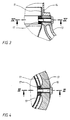
- FIGS. 3 and 4 show a second exemplary embodiment of a line 11 carrying hot exhaust gases, which relates to the situation shown in FIGS. 1 and 2.
- the line 11 is, however, smooth-walled in the fastening plane and has the undersize required for deformation in relation to the casing 13 in the assembled state.
- a clamping ring 19 is loosely inserted in the interior of the conduit 11 and bears with its radially projecting lugs 17 on the inside of the conduit 11.
- the attachment of line 11 and tension ring 19 to the casing 13 is again carried out with screws 16, which penetrate the line 11 through holes and are screwed into the lugs 17.
- Line 11 and clamping ring 19 are deformed as already described after tightening the screws 16.
- the advantage of this embodiment is that the line 11 can be formed without a weld seam or with fewer weld seams. Furthermore, different materials can be selected for line 11 and clamping ring 19.
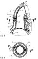
- FIGS. 5 and 6 show a third exemplary embodiment, which shows a line 11 carrying hot exhaust gases inside a liquid-cooled envelope 13 at the exhaust gas outlet Cylinder of an internal combustion engine shows.
- the attachment between line 11 and sheathing 13 takes place by means of two screws 16 arranged radially in a cross-sectional plane.
- the cross-sectional plane with screws 16 is arranged approximately in the middle of the longitudinal extent of line 11.
- the wall of the line 11 is equipped with lugs 17.
- a radial undersize is also present in the second exemplary embodiment in the cold state between the line 11 in the region of each lug 17 and the casing 13.
- the lugs 17 form shoulders 20, 21 projecting radially over the outer circumference of the line 11 and two corresponding cutouts 18 in the sheath 13, by means of which the line 11 is fixed in the axial direction.
Landscapes
- Engineering & Computer Science (AREA)
- Chemical & Material Sciences (AREA)
- Combustion & Propulsion (AREA)
- Mechanical Engineering (AREA)
- General Engineering & Computer Science (AREA)
- Exhaust Silencers (AREA)
- Connection Of Plates (AREA)
- Clamps And Clips (AREA)
- Rigid Pipes And Flexible Pipes (AREA)
Description
- Die Erfindung bezieht sich auf eine heiße Gase führende Leitung für eine Brennkraftmaschine gemäß dem Oberbegriff von Patentanspruch 1. Mit einer derartigen Anordnung wird verhindert, daß das heiße Gas unmittelbaren Kontakt mit der flüssigkeitsgekühlten Umhüllung bekommt, wodurch der Wärmezufluß in das Kühlmittel klein gehalten wird.
- Eine gattungsbildende Anordnung einer heiße Gase führenden Leitung ist aus dem DE-GM 80 13 256 bekannt. Mehrere flanschartig ausgebildete Knaggen sind über die Länge verteilt an jeder Längsseite der dünnwandigen Leitung angeordnet und liegen an einer korrespondierenden Flanschfläche der flüssigkeitsgekühlten Umhüllung an. Die Befestigung der Leitung erfolgt durch senkrecht zur Flanschfläche eingesetzte Schrauben. Die im Betrieb auftretenden hohen Temperaturen der heißen Gase führen zu erheblichen Wärmedehnungsdifferenzen zwischen Leitung und Umhüllung, die nur zum Teil von der Befestigung kompensiert werden. Nicht kompensierbare Wärmedehnungen führen zu Zwangsdruckkräften, die nicht kalkulierbare Werkstoffbeanspruchungen zur Folge haben. Die Auswirkungen der Zwangsdruckkräfte überlagern sich mit den betriebsbedingten Beanspruchungen einer Brennkraftmaschine wie Vibration und Gaspulsation zu betriebsgefährdenden Beanspruchungen der Leitung.
- Es ist deshalb Aufgabe der Erfindung, eine heiße Gase führende Leitung für eine Brennkraftmaschine zu schaffen, die eine betriebssichere Verbindung zwischen Leitung und flüssigkeitsgekühlter Umhüllung ergibt.
- Diese Aufgabe wird erfindungsgemäß mit den kennzeichnenden Merkmalen von Patentanspruch 1 gelöst. Nach Einbau der Leitung in die Umhüllung sind die Wandungsabschnitte zwischen den Knaggen mindestens in Bereichen beiderseits der Querschnittebene der Schrauben durch Zugspannungen verformt. Die Verformung liegt in der Größenordnung der bei Betriebstemperatur zu erwartenden Wärmedehnung. Die im kalten Zustand erzeugte Verformung der Leitung geht bei Erwärmung zurück, wobei die Zugspannungen abgebaut werden. Bei dieser gewissermaßen programmierten Wärmedehnung der Leitung ist die Gefahr von unkalkulierbaren Werkstoffbeanspruchungen durch Zwangskräfte vermieden. Weitere Ausgestaltungen der Erfindung ergeben sich aus den Ansprüchen 2 bis 6.
- Die mit der Erfindung erzielten Vorteile bestehen insbesondere darin, daß die Erzeugung der Leitungsverformung zwangsläufig mit der Montage der Befestigungsmittel erfolgt, daß die Befestigungsmittel von außen kontrollierbar sind, daß sich das Untermaß, das die Verformung der Leitung ergibt, eindeutig bei der Montage messen läßt, daß sich eine kostengünstige Herstellung der Leitungsbefestigung ergibt.
- Drei Ausführungsbeispiele der Erfindung sind in den Zeichnungen dargestellt und werden nachstehend näher beschrieben. Es zeigt:
- Fig. 1 Teilquerschnitt einer Abgasturbine mit einer heiße Gase führenden Leitung im Abgasaustritt nach Linie I-I in Fig. 2;
- Fig. 2 Schnitt durch die Befestigungsebene der Leitung nach Linie II-II in Fig. 1;
- Fig. 3 Ausschnitt einer heiße Gase führenden Leitung mit eingefügtem Spannring nach Linie III-III in Fig. 4;
- Fig. 4 Schnitt durch die Befestigungsebene der Leitung nach Linie IV-IV in Fig. 3;
- Fig. 5 Teilquerschnitt eines Brennkraftmaschine mit einer heiße Gase führenden Leitung im Abgasaustritt eines Zylinders nach Linie V-V in Fig. 6;
- Fig. 6 Schnitt durch die Befestigungsebene der Leitung nach Linie VI-VI in Fig. 5.
- Zwischen einer Abgasturbine 12 und einer Auspuffleitung 14 ist eine die heißen Abgase der Abgasturbine 12 aufnehmende Leitung 11 angeordnet (Fig. 1 und Fig. 2). Die dünnwandig ausgebildete Leitung 11 ist von einer flüssigkeitsgekühlten Umhüllung 13 umgeben, an der die Leitung 11 und die Auspuffleitung 14 befestigt sind. Die Verbindung zwischen Leitung 11 und Umhüllung 13 erfolgt am Austrittsende 15 der Leitung 11 durch vier radial und in einer Querschnittsebene angeordnete Schrauben 16. Die Wand der Leitung 11 ist in der Querschnittsebene entsprechend der Umfangsverteilung der Schrauben 16 mit linsenförmigen Knaggen 17 ausgestattet, die jeweils ein den Schrauben 16 entsprechendes Mutterngewinde aufweisen.
- Im Montageanfangszustand, wenn die Leitung 11 in die Umhüllung 13 eingeschoben ist, weist die Leitung 11 im Bereich jedes Knaggen 17 ein radiales Untermaß auf. Durch die in die Mutterngewinde der Knaggen 17 eingreifenden und fest angezogenen Schrauben 16 wird die Leitung 11 unter Verformung ihrer Querschnittskontur im Bereich jedes Knaggen 17 gegen die Umhüllung gezogen. Das ursprünglich vorhandene radiale Untermaß ist danach nicht mehr vorhanden. Dafür ist die Leitung 11 in der Querschnittsebene der Schrauben 16 in den Wandungsabschnitten zwischen den Knaggen 17 zu der in Fig. 2 mit vollen Linien dargestellten Kontur verformt. Das die Verformung bewirkende radiale Untermaß zwischen den Knaggen 17 an der Leitung 11 und der Umhüllung 13 wird so gewählt, daß sich eine Verformung einstellt, die in der Größenordnung der bei Betriebstemperatur der Leitung 11 zu erwartenden Wärmedehnung liegt. Daraus ergibt sich bei Betriebstemperatur der Leitung 11 infolge der Wärmedehnung ein Rückgang der im kalten Zustand erzeugten Verformung. In den Wandungsabschnitten zwischen den Knaggen 17 nimmt die Leitung 11 dann die in Fig. 2 strichpunktiert gezeichnete Kontur an. Eine Behinderung der Wärmedehnung kann nicht eintreten. Im betriebswarmen Zustand ist die Leitung 11 dadurch von betriebsgefährdenden Zwangskräften, die aus behinderter Wärmedehnung resultieren, entlastet.
- Eine in Umfangsrichtung unregelmäßige Anordnung der Knaggen 17, wie in Fig. 6 beispielhaft dargestellt, verbessert das Schwingungsverhalten der Leitung 11. Die ungleich langen Wandabschnitte zwischen den Knaggen 17 haben unterschiedliche Eigenfrequenzen, so daß die von der pulsierenden Abgasströmung angeregten Schwingungen der Leitung 11 sich auf diese Weise nicht zu einer betriebsgefährdenden Resonanzschwingung aufschaukeln können.
- In den Figuren 3 und 4 ist ein zweites Ausführungsbeispiel einer heiße Abgase führenden Leitung 11 dargestellt, das sich auf die in Fig. 1 und 2 gezeigte Situation bezieht. Die Leitung 11 ist allerdings in der Befestigungsebene glattwandig ausgebildet und weist gegenüber der Umhüllung 13 im Montagezustand das zur Verformung erforderliche Untermaß auf. Im Innern der Leitung 11 ist ein Spannring 19 lose eingefügt, der mit seinen radial vorspringenden Knaggen 17 an der Innenseite der Leitung 11 anliegt. Die Befestigung von Leitung 11 und Spannring 19 an der Umhüllung 13 erfolgt wieder mit Schrauben 16, die die Leitung 11 an Durchgangslöchern durchdringen und in die Knaggen 17 eingeschraubt werden. Leitung 11 und Spannring 19 sind nach dem Anziehen der Schrauben 16 wie vorstehend schon beschrieben verformt. Der Vorteil dieser Ausführung liegt darin, daß die Leitung 11 ohne Schweißnaht bzw. mit weniger Schweißnähten ausgebildet werden kann. Ferner sind für Leitung 11 und Spannring 19 unterschiedliche Werkstoffe wählbar.
- In den Figuren 5 und 6 ist ein drittes Ausführungsbeispiel dargestellt, das eine heiße Abgase führende Leitung 11 innerhalb einer flüssigkeitsgekühlten Umhüllung 13 am Abgasaustritt eines Zylinders einer Brennkraftmaschine zeigt. Die Befestigung zwischen Leitung 11 und Umhüllung 13 erfolgt mittels zweier, radial in einer Querschnittsebene angeordneter Schrauben 16. Die Querschnittsebene mit den Schrauben 16 ist etwa in der Mitte der Längserstreckung der Leitung 11 angeordnet. Zur Aufnahme der Schrauben 16 ist die Wand der Leitung 11 mit Knaggen 17 ausgestattet. Wie für das Ausführungsbeispiel in Fig. 1 und 2 beschrieben, ist auch beim zweiten Ausführungsbeispiel im kalten Zustand zwischen der Leitung 11 im Bereich jeden Knaggens 17 und der Umhüllung 13 ein radiales Untermaß vorhanden. Durch das Anziehen der Schrauben 16 wird die Leitung 11 in den Wandungsabschnitten zwischen den Knaggen 17 durch eine Zugspannung verformt. Die sich dabei einstellende Querschnittskontur der Leitung 11 zwischen den Knaggen 17 in der Befestigungsebene der Schrauben 16 entspricht der Darstellung in Fig. 2 für den kalten und für den betriebswarmen Zustand.
- Die Knaggen 17 bilden radial über den Außenumfang der Leitung 11 auskragende, zwei entsprechenden Aussparungen 18 in der Umhüllung 13 zusammenwirkende Schultern 20, 21, durch die die Leitung 11 in axialer Richtung fixiert ist.
Claims (6)
Applications Claiming Priority (2)
| Application Number | Priority Date | Filing Date | Title |
|---|---|---|---|
| DE3743851A DE3743851C1 (de) | 1987-12-23 | 1987-12-23 | Abgasleitung fuer eine Brennkraftmaschine |
| DE3743851 | 1987-12-23 |
Publications (2)
| Publication Number | Publication Date |
|---|---|
| EP0348451A1 EP0348451A1 (de) | 1990-01-03 |
| EP0348451B1 true EP0348451B1 (de) | 1992-01-22 |
Family
ID=6343463
Family Applications (1)
| Application Number | Title | Priority Date | Filing Date |
|---|---|---|---|
| EP88909511A Expired - Lifetime EP0348451B1 (de) | 1987-12-23 | 1988-11-09 | Heisse gase führende leitung für eine brennkraftmaschine |
Country Status (8)
| Country | Link |
|---|---|
| US (1) | US5022227A (de) |
| EP (1) | EP0348451B1 (de) |
| JP (1) | JPH02502470A (de) |
| KR (1) | KR930011562B1 (de) |
| CN (1) | CN1009124B (de) |
| DE (2) | DE3743851C1 (de) |
| SU (1) | SU1766274A3 (de) |
| WO (1) | WO1989005911A1 (de) |
Families Citing this family (7)
| Publication number | Priority date | Publication date | Assignee | Title |
|---|---|---|---|---|
| DE4021326C1 (de) * | 1990-07-04 | 1991-09-05 | Mtu Friedrichshafen Gmbh | |
| DE4229467A1 (de) * | 1992-09-03 | 1994-03-10 | Mtu Friedrichshafen Gmbh | Lagereinrichtung für die Abgassammelleitung einer Brennkraftmaschine |
| US5408828A (en) * | 1993-12-10 | 1995-04-25 | General Motors Corporation | Integral cast diffuser for a catalytic converter |
| AT413130B (de) * | 2003-09-23 | 2005-11-15 | Ge Jenbacher Ag | Brennkraftmaschine |
| RU2310085C2 (ru) * | 2005-12-09 | 2007-11-10 | Открытое акционерное общество "Заволжский моторный завод" | Экран теплоизолирующий для двигателя внутреннего сгорания |
| CN102943716A (zh) * | 2012-11-29 | 2013-02-27 | 河南创世电机科技有限公司 | 一种通用小型汽油机高功率用气缸盖 |
| AT522795B1 (de) * | 2019-10-07 | 2021-02-15 | Avl List Gmbh | Zylinderkopf einer brennkraftmaschine |
Family Cites Families (9)
| Publication number | Priority date | Publication date | Assignee | Title |
|---|---|---|---|---|
| DE926578C (de) * | 1952-04-13 | 1955-04-21 | Bayerische Motoren Werke Ag | Vorrichtung zum Verhindern des Anlaufens von verchromten Auspuff-rohrkruemmern fuer Brennkraftmaschinen, insbesondere fuer Kraftraeder |
| US3908369A (en) * | 1974-05-06 | 1975-09-30 | Clark Equipment Co | Turbo-supercharger exhaust |
| DE2602434A1 (de) * | 1976-01-23 | 1977-07-28 | Daimler Benz Ag | Im zylinderkopf einer brennkraftmaschine befindliche gasfuehrungskanaele und deren herstellung |
| US4086763A (en) * | 1976-04-13 | 1978-05-02 | Fuji Jukogyo Kabushiki Kaisha | Thermal reactor system for internal combustion engine |
| US4197704A (en) * | 1976-06-11 | 1980-04-15 | Honda Giken Kogyo Kabushiki Kaisha | Exhaust manifold for internal combustion engine |
| DE2744964A1 (de) * | 1977-10-06 | 1979-04-19 | Kloeckner Humboldt Deutz Ag | Abgasleitungssystem fuer mehrzylindrige hubkolbenbrennkraftmaschinen |
| DE8013256U1 (de) * | 1980-05-16 | 1986-10-02 | Mtu Motoren- Und Turbinen-Union Friedrichshafen Gmbh, 7990 Friedrichshafen | Abgassammelleitung für Brennkraftmaschinen mit mehreren Zylindern |
| US4430856A (en) * | 1981-11-13 | 1984-02-14 | Deere & Company | Port liner and method of assembly |
| DE3635478C1 (de) * | 1986-10-18 | 1988-02-11 | Mtu Friedrichshafen Gmbh | Abgasleitung fuer eine aufgeladene,mehrzylindrige Brennkraftmaschine |
-
1987
- 1987-12-23 DE DE3743851A patent/DE3743851C1/de not_active Expired
-
1988
- 1988-11-09 US US07/423,409 patent/US5022227A/en not_active Expired - Fee Related
- 1988-11-09 WO PCT/DE1988/000697 patent/WO1989005911A1/de not_active Ceased
- 1988-11-09 KR KR1019890701591A patent/KR930011562B1/ko not_active Expired - Fee Related
- 1988-11-09 EP EP88909511A patent/EP0348451B1/de not_active Expired - Lifetime
- 1988-11-09 JP JP63508784A patent/JPH02502470A/ja active Granted
- 1988-11-09 DE DE8888909511T patent/DE3868059D1/de not_active Expired - Lifetime
- 1988-12-23 CN CN88108762A patent/CN1009124B/zh not_active Expired
-
1989
- 1989-06-07 SU SU894614201A patent/SU1766274A3/ru active
Also Published As
| Publication number | Publication date |
|---|---|
| DE3868059D1 (de) | 1992-03-05 |
| EP0348451A1 (de) | 1990-01-03 |
| KR900700748A (ko) | 1990-08-16 |
| CN1034606A (zh) | 1989-08-09 |
| SU1766274A3 (ru) | 1992-09-30 |
| JPH0411726B2 (de) | 1992-03-02 |
| WO1989005911A1 (fr) | 1989-06-29 |
| DE3743851C1 (de) | 1989-05-03 |
| JPH02502470A (ja) | 1990-08-09 |
| CN1009124B (zh) | 1990-08-08 |
| KR930011562B1 (ko) | 1993-12-11 |
| US5022227A (en) | 1991-06-11 |
Similar Documents
| Publication | Publication Date | Title |
|---|---|---|
| DE69827224T2 (de) | Vorrichtung zur Behandlung von Verbrennungsabgasen für Kraftfahrzeug | |
| DE69408424T2 (de) | Integraler Gussdiffusor für einen Katalysator | |
| EP0379538B1 (de) | Den raum zwischen v-förmig angeordneten zylinderreihen einer brennkraftmaschine überdeckende haube | |
| EP0348451B1 (de) | Heisse gase führende leitung für eine brennkraftmaschine | |
| DE29907590U1 (de) | Abkoppelelement zur Abkopplung von Schwingungen | |
| EP3781856B1 (de) | Spannvorrichtung zum abdichten und verbinden zweier rohre | |
| DE19808068A1 (de) | Brennstoffeinspritzventil | |
| DE19628798B4 (de) | Abgaskrümmer zur Abgasführung aus einer Brennkraftmaschine | |
| EP2522824A1 (de) | Abgasanlagenkomponente | |
| DE2653263B2 (de) | Abgasleitung | |
| DE3631312C1 (de) | Einrichtung zur Halterung von Abgasleitungen | |
| DE69900391T2 (de) | Flexibles Rohr mit feinmaschig geflochtener Auskleidung | |
| DE102007002636B4 (de) | Feder-Dämpfer-Element für flexible Leitungselemente | |
| EP0698180B1 (de) | Abgasleitung | |
| EP3808950B1 (de) | Mischeranordnung | |
| DE10244107A1 (de) | Schlauchleitung und Verfahren zu deren Herstellung | |
| DE29916158U1 (de) | Katalytischer Konverter zum Reinigen von Abgas und Abgasreinigungsanordnung mit einem katalytischen Konverter | |
| DE102015016155A1 (de) | Abgassystem für eine Brennkraftmaschine | |
| DE2458994A1 (de) | Anordnung zur katalytischen reinigung von abgasen | |
| EP0937873B1 (de) | Anschlussvorrichtung für ein Abgasrohr einer Brennkraftmaschine | |
| DE4021326C1 (de) | ||
| DE19858634A1 (de) | Flexschlauch | |
| DE4224317C1 (de) | Einrichtung zur Befestigung eines Gasführungskanals innerhalb eines Gehäuses einer Abgasleitung | |
| DE2407263A1 (de) | Einrichtung zur katalytischen abgasreinigung | |
| EP0276648A1 (de) | Auslasskrümmer für Verbrennungsmotoren |
Legal Events
| Date | Code | Title | Description |
|---|---|---|---|
| PUAI | Public reference made under article 153(3) epc to a published international application that has entered the european phase |
Free format text: ORIGINAL CODE: 0009012 |
|
| 17P | Request for examination filed |
Effective date: 19890818 |
|
| AK | Designated contracting states |
Kind code of ref document: A1 Designated state(s): CH DE FR GB IT LI |
|
| 17Q | First examination report despatched |
Effective date: 19910417 |
|
| ITF | It: translation for a ep patent filed | ||
| GRAA | (expected) grant |
Free format text: ORIGINAL CODE: 0009210 |
|
| AK | Designated contracting states |
Kind code of ref document: B1 Designated state(s): CH DE FR GB IT LI |
|
| ET | Fr: translation filed | ||
| REF | Corresponds to: |
Ref document number: 3868059 Country of ref document: DE Date of ref document: 19920305 |
|
| GBT | Gb: translation of ep patent filed (gb section 77(6)(a)/1977) | ||
| PLBE | No opposition filed within time limit |
Free format text: ORIGINAL CODE: 0009261 |
|
| STAA | Information on the status of an ep patent application or granted ep patent |
Free format text: STATUS: NO OPPOSITION FILED WITHIN TIME LIMIT |
|
| 26N | No opposition filed | ||
| PGFP | Annual fee paid to national office [announced via postgrant information from national office to epo] |
Ref country code: CH Payment date: 19931013 Year of fee payment: 6 |
|
| PGFP | Annual fee paid to national office [announced via postgrant information from national office to epo] |
Ref country code: GB Payment date: 19931014 Year of fee payment: 6 Ref country code: DE Payment date: 19931014 Year of fee payment: 6 |
|
| PGFP | Annual fee paid to national office [announced via postgrant information from national office to epo] |
Ref country code: FR Payment date: 19931018 Year of fee payment: 6 |
|
| PG25 | Lapsed in a contracting state [announced via postgrant information from national office to epo] |
Ref country code: GB Effective date: 19941109 |
|
| PG25 | Lapsed in a contracting state [announced via postgrant information from national office to epo] |
Ref country code: LI Effective date: 19941130 Ref country code: CH Effective date: 19941130 |
|
| GBPC | Gb: european patent ceased through non-payment of renewal fee |
Effective date: 19941109 |
|
| PG25 | Lapsed in a contracting state [announced via postgrant information from national office to epo] |
Ref country code: FR Effective date: 19950731 |
|
| REG | Reference to a national code |
Ref country code: CH Ref legal event code: PL |
|
| PG25 | Lapsed in a contracting state [announced via postgrant information from national office to epo] |
Ref country code: DE Effective date: 19950801 |
|
| REG | Reference to a national code |
Ref country code: FR Ref legal event code: ST |
|
| PG25 | Lapsed in a contracting state [announced via postgrant information from national office to epo] |
Ref country code: IT Free format text: LAPSE BECAUSE OF NON-PAYMENT OF DUE FEES;WARNING: LAPSES OF ITALIAN PATENTS WITH EFFECTIVE DATE BEFORE 2007 MAY HAVE OCCURRED AT ANY TIME BEFORE 2007. THE CORRECT EFFECTIVE DATE MAY BE DIFFERENT FROM THE ONE RECORDED. Effective date: 20051109 |