EP0348227B1 - Dispositif d'obturation latérale pour machine de coulée continue de bande - Google Patents
Dispositif d'obturation latérale pour machine de coulée continue de bande Download PDFInfo
- Publication number
- EP0348227B1 EP0348227B1 EP89306400A EP89306400A EP0348227B1 EP 0348227 B1 EP0348227 B1 EP 0348227B1 EP 89306400 A EP89306400 A EP 89306400A EP 89306400 A EP89306400 A EP 89306400A EP 0348227 B1 EP0348227 B1 EP 0348227B1
- Authority
- EP
- European Patent Office
- Prior art keywords
- side wall
- refractory layer
- chamber
- layer
- wear
- Prior art date
- Legal status (The legal status is an assumption and is not a legal conclusion. Google has not performed a legal analysis and makes no representation as to the accuracy of the status listed.)
- Expired - Lifetime
Links
Images


Classifications
-
- B—PERFORMING OPERATIONS; TRANSPORTING
- B22—CASTING; POWDER METALLURGY
- B22D—CASTING OF METALS; CASTING OF OTHER SUBSTANCES BY THE SAME PROCESSES OR DEVICES
- B22D11/00—Continuous casting of metals, i.e. casting in indefinite lengths
- B22D11/06—Continuous casting of metals, i.e. casting in indefinite lengths into moulds with travelling walls, e.g. with rolls, plates, belts, caterpillars
- B22D11/0637—Accessories therefor
- B22D11/0648—Casting surfaces
- B22D11/066—Side dams
Definitions
- the present invention relates to a side wall construction of a continuous caster according to the preamble of claim 1.
- One such continuous caster is a synchronous belt caster which includes a pair of endless circulating bodies in the form of belts which define a funnel-like path having a wider inlet and a narrower outlet so as to form a solidified shell during throughput of molten metal.
- the endless belts form a moving wall of the caster and a pair of stationary side walls is provided for defining the aforementioned funnel-like path.
- Each of the side walls has a wider transverse width at the portion in the vicinity of the inlet and a narrower transverse width at the portion in the vicinity of the outlet so as to define the funnel-like path, gradually narrowing the path area toward the outlet.
- Molten metal such as molten pig iron or molten steel
- molten metal is supplied to such a belt caster through the inlet and cooled by transference of heat between the belts for gradually forming and growing a solidified shell in the caster.
- the cast block is fed out or withdrawn through the outlet.
- the thickness of the solidified shell is reduced at a predetermined reduction rate by the essentially funnel shaped path.
- Japanese Patent First (unexamined) Publication (Tokkai) Showa 58-218360 proposes a side wall construction provided with a refractory layer at the transverse center thereof.
- the refractory is supported on a metallic wall.
- the metallic wall extends along the side edge of the refractory and establishes a tight contact with the endless belt.
- JPA 58-218349 discloses a continuous caster in which the side edge plates are located between continuous circulating bodies and are formed from a refractory material. Sliding plates are mounted on the surfaces of the side edge plates which are in contact with the continuously circulating bodies to prevent leakage of molten steel.
- JPA 62-203644 discloses a side edge plate for a continuous caster formed from a refractory material and a metallic support.
- the metallic support includes channels to provide cooling fluid and lubricant.
- FRA 2613646 the use of side walls in the form of refractory plates located at each side of the belts and of sufficient dimensions to seal the casting chamber, is disclosed.
- Each refractory plate has a plane surface.
- the refractory layer Despite the presence of the refractory layer, it is still difficult to provide satisfactory delay of solidification. Namely, when the temperature of the melt is relative low or when the speed of the melt flowing along the path is relatively low, substantial heat exchange occurs between the melt and the refractory resulting in growth of a solidified shell on the refractory. In such cases, the solidified shell grown on the refractory is drawn together with the shells grown on the belt or the metallic edge portion of the side wall. If the stiffness of the solidified shell on the refractory is relatively low, it would still be possible to compress the shell during travel along the path toward the outlet.
- the stiffness of the shell is substantial, to such an extent that it can resist the compression force exerted by the walls of the caster, since the solidified shell forms a wedge shaped block, metal penetration may occur. If metal penetration occurs, movement of the solidified shell at the portion in the vicinity of the side wall can be completely prevented and movement of the solidified shell at the transverse central portion where the solidifying block mates with the belt is permitted to occur. This tends to cause break-out of the cast block. Alternatively, because of the excessive thickness of the shell, the belt will be subjected to substantial bending stress thus causing damage to the belt.
- the material used to form the refractory layer on the side wall may be selected from silica, boron nitride, sialon and so forth. Such materials generally have high heat conductivities enabling greater heat transfer from the metal, to promote growth of the solidified shell when such material is solely used for forming the refractory layer. In addition, these refractory materials have relatively large linear expansion coefficients. Therefore, deformation can be caused in the metallic side wall when there is substantial thermal expansion of the refractory. On the other hand, when material having a low heat transfer coefficient, such as molten silica brick, is used for forming the refractory layer on the side wall, a solidified layer can grow not only at the metallic side edge portion but also on the refractory layer.
- the solidified shell formed on the refractory layer tends to cause wearing of the surface of the refractory layer. Therefore, a refractory layer formed of a material having a low heat transfer coefficient would not be suitable for the belt caster for long period of use.
- Japanese Patent First (unexamined) Publication (Tokkai) Showa 58-218326 discloses a method of positively heating the refractory so as to prevent the melt from solidifying.
- a side wall for a continuous caster of the type comprising a pair of endless circulating bodies forming moving walls of the caster and a pair of side walls forming stationary walls of said caster wherein the stationary walls are cooperative with said moving walls for defining the interior surface of a casting chamber to which molten metal is introduced for the purpose of casting a continuous cast block, said side wall comprising:
- the refractory layer is a double layer construction composed of a heat insulating refractory layer and a wear-resistant refractory layer.
- the heat insulating layer may be provided in a region below the meniscus of the molten metal.
- the wear-resistant refractory layer may be formed of a material having a shore hardness at a predetermined high temperature range greater than the shore hardness of the cast block immediately after casting.
- the material of the wear-resistant refractory layer is preferably selected to have a shore hardness of 15 at 1200°C.
- the wear-resistant refractory layer is formed of a material selected from silicon nitride, sialon, alumina, mullite and zirconium boride or a composition of any one of these and boron nitride.
- the heat insulating refractory layer may be formed of a material selected from MgO board, SiO2 type board or molten silica brick.
- a second heat insulative layer, which partially defines the inside surface of the chamber may be provided. Such a second layer may be formed of a material selected among asbestos fabric, glass fiber fabric or rock wool.
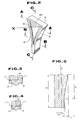
- the belt caster includes a pair of metallic endless belts 1 and 2 forming the moving walls of the caster, and a pair of side walls 4 and 5 forming the stationary walls of the caster.
- Each of the endless belts 1 and 2 is associated with guide rollers 3a, 3b and 3c, one of which is drivingly connected to a driving device to be rotatingly driven for circulating the belt.
- the portion of the belt extending between the guide rollers 3a and 3c forms the moving wall of the caster and is associated with a cooling pad 7a or 7b, to which coolant, such as cooling water, is circulated for cooling the associated one of the belts, 1 or 2.
- coolant such as cooling water
- the side walls 4 and 5 are formed into an essentially funnel shape in front elevation so as to have the greatest width at the top (inlet) end and gradually decreasing in width in a downward direction towards the bottom (outlet) end.
- the side walls 4 and 5 also have a predetermined length of constant width portion adjacent the lower end thereof. Therefore, the belts 1 and 2 and the side walls 4 and 5 form an essentially wedge-shaped casting chamber. Molten metal, such as molten pig iron or molten steel, is supplied to the casting chamber from the top end from a tundish via a nozzle 6.
- the side walls 4 and 5 include metallic walls 8.
- Each metal wall 8 is formed with an essentially triangular recess 8a defined by frame-like edge portions 9.
- a refractory layer 10 is disposed within the recess 8a to complete the side wall assembly.
- the melt is cooled by heat exchange with the belts 1 and 2 and thus gradually grows a solidified shell on the belts. Also, the portion of the melt interfacing with the edge portions 9 of the side walls 4 and 5 is also cooled by heat exchange with the edge portions and thus grows a solidified shell. The solidified shell growing on the edge of the side walls 4 and 5 serves to prevent the melt entering the space between the belt and the side wall. During travel through the casting chamber, the melt is thus gradually solidified and withdrawn through the lower end outlet.
- the metallic wall 8 of the side wall 4 and 5 has a coolant path 11 for circulating coolant, such as cooling water, for cooling the metallic wall.
- coolant such as cooling water
- the major part of the refractory layer 10 is enclosed by the recess 8a.
- the refractory layer 10 has an essentially triangular cross section and has a peak X located at the transverse center of the refractory layer 10 and projecting into the casting chamber. The extent to which peak X projects into the chamber is greatest at the inlet end and gradually decreases to zero towards the outlet end.
- the profile of the refractory layer has a positive taper with a gradient of ⁇ 1/ l1, where ⁇ 1 is the peak height difference between the inlet end and the outlet end of the refractory layer and l1 is length of the peak.
- the thickness of the edge portion 9 of the metal wall 8 gradually increases towards the outlet end.
- the gradient of the edge portion 9 is ⁇ 2/ l2, where ⁇ 2 is the difference between the thickness of edge portion 9 at the inlet end and the thickness of the edge portion at the outlet end, and l2 is the overall length of the side wall.
- the metallic wall 8 is cooled by coolant circulating inside the coolant passage, heat exchange occurs between the melt and the edge portions 9 which define a portion of the inside surface of the chamber, thereby cooling the melt. Consequently, a solidified shell is grown on the edge portions 9.
- the solidified shell is released from the surface of the exposed surfaces of the side walls 4 and 5 and will not be subjected to break out or give rise to defects in the cast block because of the presence of the opposite taper of the refractory layer and the edge portions 9.
- the casting operation was performed very smoothly without causing break out or defects in the cast block.
- a coolant passage 11a extending through the major section of the metallic wall 8, and a coolant passage 11b extending through the edge portions 9 of the wall are provided.
- the heat insulative refractory layer 10a is an inner layer located adjacent to the metallic wall 8 and the wear-resistant refractory layer 10b is an outer layer which comes into contact with the melt in the chamber.
- a section heat insulative layer 10c is at least partially formed on the surface of the wear-resistant layer 10b.
- the heat insulative layer 10c is formed in an area starting immediately below the meniscus line M and terminating at the portion where a constant width section starts at the outlet side.
- the heat insulative refractory layer 10a is selected from a material having a heat transfer rate lower than or equal to 0.002 cal/cm.s.°C.
- MgO board, SiO2 type board, molten silica brick may be selected for forming the heat insulative refractory layer.
- the material for forming the heat insulative layer 10c is preferably selected from, for example, asbestos wool, glass fiber fabrics, rock wools.
- the preferred thickness of the heat insulative layer 10c to be formed on the wear-resistant refractory layer 10b is in a range of 1 mm to 3 mm. When the thickness of the heat insulative layer 10c is less than 1 mm heat insulation becomes insufficient.
- the material of the wear-resistant refractory layer preferably has a high spalling resistance and mechanical strength, particularly as the shore hardness of the cast block immediately after withdrawal from the casting chamber is less than or equal to 10. Therefore, the wear-resistant refractory layer should have a shore hardness greater than or equal to 10.
- the material for the wear-resistant refractory layer is selected to have a shore hardness greater than or equal to 15 at a temperature of 1200°C. Materials satisfying this condition include; silicon nitride, sialon, alumina, mullite, zirconium boride or compositions of the above-mentioned material and boron-nitride.
- the thickness of the wear-resistant refractory layer 10b is in a range of 2 mm to 10 mm. If the thickness of the wear-resistant refractory layer is less than 2 mm, it is easy to break thus making handling difficult. Furthermore, such thin layers may not have satisfactory resistance against heat shock and thus may break when subjected to heat shock. On the other hand, when the thickness of the wear-resistant refractory layer 10b is thicker than 10 mm, heat absorption at the initial stage of casting becomes substantial and causes the formation of solidified shell thereon.
- the thickness of melting out of the refractory was approximately 1 mm for a casting length of 300 m. In this comparative example, break out was observed.
- the force required for withdrawing the cast block was increased at the initial stage of casting. After casting a length of 6 m, break out was observed. In contrast, casting was smoothly performed without causing melting of the refractory when the MgO/Sialon/BN refractory material was used.
- line A shows the temperature variation in the wear-resistant refractory layer when the asbestos layer was not attached and line B shows the temperature variation in the wear-resistant refractory layer when coupled with the asbestos layer.
- the temperature in both cases become substantially equal to one another 14 seconds after starting the casting operation.
- the heat insulative effect of the asbestos layer resulted in no formation of a solidified shell, even during the low temperature period, i.e. within approximately 9 sec. of starting the casting operation.
- slight solidification was observed in the period up to 5 sec. after the start of casting.
- the present invention is applicable to any type of continuous caster which employs a side wall having a refractory layer.
Landscapes
- Engineering & Computer Science (AREA)
- Mechanical Engineering (AREA)
- Continuous Casting (AREA)
Claims (11)
- Paroi latérale pour une machine de coulée continue du type comprenant une paire de corps circulants sans fin (1, 2) constituant des parois mobiles de la machine et une paire de parois latérales (4, 5) constituant des parois fixes de la machine, les parois fixes coopérant avec les parois mobiles pour définir la surface intérieure d'une chambre de coulée dans laquelle est introduit du métal en fusion afin de couler un bloc de coulée continue, ladite paroi latérale comprenant :a) une paroi métallique (8), etb) une couche réfractaire (10, 10a, 10b, 10c), disposée sur la surface intérieure de la paroi métallique de manière à définir partiellement la surface intérieure de la chambre et à entrer en contact avec le métal en fusion dans la chambre, la couche réfractaire étant partiellement incluse dans un évidement (8a) des parties de bords (9) des parois métalliques qui s'étendent au-delà de la couche réfractaire, définissent une partie de la surface intérieure de la chambre et entrent en contact avec le métal en fusion dans la chambre, caractérisée en ce que la couche réfractaire présente une section sensiblement triangulaire dont la pointe (X) est disposée de manière à faire saillie dans la chambre, l'ampleur de cette saillie diminuant dans la direction d'écoulement.
- Paroi latérale selon la revendication 1, caractérisée en ce que la pointe de la section triangulaire est arrondie.
- Paroi latérale selon la revendication 1 ou 2, caractérisée en ce que la pointe de la section triangulaire est centrale par rapport aux parois latérales.
- Paroi latérale selon l'une quelconque des revendications précédentes, caractérisée en ce que la couche réfractaire comprend une couche réfractaire intérieure calorifuge (10a) et une couche réfractaire extérieure résistante à l'usure (10b), dont la surface définit partiellement la surface intérieure de la chambre.
- Paroi latérale selon la revendication 4, caractérisée en ce qu'elle comprend en outre une seconde couche calorifuge (10c), formée sur la surface de la couche réfractaire résistante à l'usure.
- Paroi latérale selon la revendication 5, caractérisée en ce que la seconde couche calorifuge est prévue dans une région située en dessous du ménisque (M) du métal en fusion.
- Paroi latérale selon l'une quelconque des revendications 4 à 6, caractérisée en ce que la seconde couche calorifuge est constituée d'un matériau choisi parmi les suivants : tissu d'amiante, tissu de fibre de verre ou laine de roche.
- Paroi latérale selon l'une quelconque des revendications 4 à 7, caractérisée en ce que la couche réfractaire résistante à l'usure est constituée d'un matériau possédant, dans une plage prédéterminée de hautes températures, une dureté Shore qui est supérieure à la dureté Shore du bloc coulé juste après la coulée.
- Paroi latérale selon l'une quelconque des revendications 4 à 8, caractérisée en ce que la matériau de la couche réfractaire résistante à l'usure possède une dureté Shore au moins égale à 15 à 1200°C.
- Paroi latérale selon l'une quelconque des revendications 4 à 9, caractérisée en ce que la couche réfractaire résistante à l'usure est constituée d'un matériau choisi parmi les suivants :nitrure de silicium, sialon, oxyde d'aluminium, mullite et borure de zirconium, ou une combinaison d'un quelconque de ces matériaux et de nitrure de bore.
- Paroi latérale selon l'une quelconque des revendications 4 à 10, caractérisée en ce que la première couche réfractaire calorifuge est constituée d'un matériau choisi parmi les suivants : plaque de MgO, plaque du type SiO₂ ou brique de silice fondue.
Applications Claiming Priority (4)
| Application Number | Priority Date | Filing Date | Title |
|---|---|---|---|
| JP155046/88 | 1988-06-24 | ||
| JP15504688A JPH01321047A (ja) | 1988-06-24 | 1988-06-24 | 薄鋳片連続鋳造機の短辺側板 |
| JP298046/88 | 1988-11-28 | ||
| JP29804688A JPH02147151A (ja) | 1988-11-28 | 1988-11-28 | 薄鋳片連続鋳造機の短辺側板 |
Publications (2)
| Publication Number | Publication Date |
|---|---|
| EP0348227A1 EP0348227A1 (fr) | 1989-12-27 |
| EP0348227B1 true EP0348227B1 (fr) | 1993-05-05 |
Family
ID=26483154
Family Applications (1)
| Application Number | Title | Priority Date | Filing Date |
|---|---|---|---|
| EP89306400A Expired - Lifetime EP0348227B1 (fr) | 1988-06-24 | 1989-06-23 | Dispositif d'obturation latérale pour machine de coulée continue de bande |
Country Status (3)
| Country | Link |
|---|---|
| US (1) | US5127462A (fr) |
| EP (1) | EP0348227B1 (fr) |
| DE (1) | DE68906312T2 (fr) |
Cited By (1)
| Publication number | Priority date | Publication date | Assignee | Title |
|---|---|---|---|---|
| DE4337399A1 (de) * | 1993-10-26 | 1995-04-27 | Mannesmann Ag | Stranggießkokille für die Erzeugung von dünnen Brammen, Platten oder Blechen aus Stahl |
Families Citing this family (4)
| Publication number | Priority date | Publication date | Assignee | Title |
|---|---|---|---|---|
| FR2666256B1 (fr) * | 1990-09-03 | 1992-10-16 | Usinor Sacilor | Installation de coulee continue entre cylindres. |
| FR2699436A1 (fr) * | 1992-12-17 | 1994-06-24 | Usinor Sacilor | Dispositif de coulée continue entre cylindres de produits métalliques minces. |
| FR2765504B1 (fr) * | 1997-07-04 | 1999-08-20 | Usinor | Face laterale d'obturation de l'espace de coulee d'une installation de coulee continue entre cylindres de bandes minces metalliques |
| KR100431832B1 (ko) * | 1999-08-26 | 2004-05-20 | 주식회사 포스코 | 쌍롤식 박판주조장치용 에지댐 |
Family Cites Families (5)
| Publication number | Priority date | Publication date | Assignee | Title |
|---|---|---|---|---|
| JPS5838640A (ja) * | 1981-08-31 | 1983-03-07 | Kawasaki Steel Corp | 薄板の連続鋳造装置 |
| JPS609553A (ja) * | 1983-06-29 | 1985-01-18 | Kawasaki Steel Corp | 絞り込み式連続鋳造機 |
| JPS6343744A (ja) * | 1986-08-11 | 1988-02-24 | Kawasaki Steel Corp | 薄鋳片連続鋳造用短辺鋳型 |
| JPS63149044A (ja) * | 1986-12-12 | 1988-06-21 | Kawasaki Steel Corp | 薄鋳片連続鋳造機の短辺側板 |
| FR2613646B1 (fr) * | 1987-04-09 | 1991-02-01 | Siderurgie Fse Inst Rech | Dispositif d'obturation laterale pour lingotiere de coulee continue entre cylindres |
-
1989
- 1989-06-23 DE DE8989306400T patent/DE68906312T2/de not_active Expired - Fee Related
- 1989-06-23 EP EP89306400A patent/EP0348227B1/fr not_active Expired - Lifetime
-
1991
- 1991-05-21 US US07/704,895 patent/US5127462A/en not_active Expired - Fee Related
Cited By (1)
| Publication number | Priority date | Publication date | Assignee | Title |
|---|---|---|---|---|
| DE4337399A1 (de) * | 1993-10-26 | 1995-04-27 | Mannesmann Ag | Stranggießkokille für die Erzeugung von dünnen Brammen, Platten oder Blechen aus Stahl |
Also Published As
| Publication number | Publication date |
|---|---|
| EP0348227A1 (fr) | 1989-12-27 |
| DE68906312D1 (de) | 1993-06-09 |
| US5127462A (en) | 1992-07-07 |
| DE68906312T2 (de) | 1993-08-12 |
Similar Documents
| Publication | Publication Date | Title |
|---|---|---|
| CA1139529A (fr) | Methode de coulee continue extra rapide de corps metalliques de forme allongee | |
| EP0348227B1 (fr) | Dispositif d'obturation latérale pour machine de coulée continue de bande | |
| KR100607428B1 (ko) | 냉각 요소 제조용 주조 몰드 및 그 몰드에서 제조되는냉각 요소 | |
| US4911226A (en) | Method and apparatus for continuously casting strip steel | |
| CA1325875C (fr) | Paroi laterale de moule pour machine de coulee continue a courroies | |
| US6173755B1 (en) | Nozzle for continuous slab casting | |
| EP0448773B1 (fr) | Moule de coulée continue et procédé de coulée continue | |
| JP3380412B2 (ja) | 溶鋼の連続鋳造用鋳型 | |
| AU738253B2 (en) | Tapping launder for a molten iron | |
| US20050280192A1 (en) | Zirconia refractories for making steel | |
| JP3289118B2 (ja) | 連続鋳造における収縮孔低減装置 | |
| US5092391A (en) | Device for the continuous casting of thin metal products between rolls | |
| EP0780176A2 (fr) | Dispositif et procédé pour la coulée continue | |
| KR20010040757A (ko) | 용융 금속의 수직 충전부에서 연속적으로 주조하는 장치 | |
| CA1240819A (fr) | Dispositif obturateur des parois laterales d'un moule de forme essentiellement rectangulaire pour installation de coulee continue | |
| CA1228969A (fr) | Appareil et methode de coulee en continu des metaux, dans un moule a parois tournantes refroidies | |
| KR100922068B1 (ko) | 노즐막힘 방지장치 | |
| KR20110120544A (ko) | 래들의 버블링 콘 인발용 지그 및 그를 이용한 인발 방법 | |
| JPH04197555A (ja) | 耐摩耗性に優れた水平連続鋳造用モールド | |
| JPH0438503B2 (fr) | ||
| JP2558187B2 (ja) | 連続鋳造用加熱鋳型 | |
| JPH0318032Y2 (fr) | ||
| JPS58218349A (ja) | 薄鋼板連続鋳造装置の固定側板 | |
| JPH07106428B2 (ja) | 金属の連続鋳造用鋳型 | |
| JPH01162545A (ja) | 薄鋳片連続鋳造機の短辺側板 |
Legal Events
| Date | Code | Title | Description |
|---|---|---|---|
| PUAI | Public reference made under article 153(3) epc to a published international application that has entered the european phase |
Free format text: ORIGINAL CODE: 0009012 |
|
| AK | Designated contracting states |
Kind code of ref document: A1 Designated state(s): DE FR GB IT |
|
| 17P | Request for examination filed |
Effective date: 19900221 |
|
| 17Q | First examination report despatched |
Effective date: 19910826 |
|
| GRAA | (expected) grant |
Free format text: ORIGINAL CODE: 0009210 |
|
| AK | Designated contracting states |
Kind code of ref document: B1 Designated state(s): DE FR GB IT |
|
| ITF | It: translation for a ep patent filed |
Owner name: BUGNION S.P.A. |
|
| REF | Corresponds to: |
Ref document number: 68906312 Country of ref document: DE Date of ref document: 19930609 |
|
| ET | Fr: translation filed | ||
| PLBE | No opposition filed within time limit |
Free format text: ORIGINAL CODE: 0009261 |
|
| STAA | Information on the status of an ep patent application or granted ep patent |
Free format text: STATUS: NO OPPOSITION FILED WITHIN TIME LIMIT |
|
| 26N | No opposition filed | ||
| PGFP | Annual fee paid to national office [announced via postgrant information from national office to epo] |
Ref country code: FR Payment date: 19990610 Year of fee payment: 11 |
|
| PGFP | Annual fee paid to national office [announced via postgrant information from national office to epo] |
Ref country code: GB Payment date: 19990623 Year of fee payment: 11 |
|
| PGFP | Annual fee paid to national office [announced via postgrant information from national office to epo] |
Ref country code: DE Payment date: 19990626 Year of fee payment: 11 |
|
| PG25 | Lapsed in a contracting state [announced via postgrant information from national office to epo] |
Ref country code: GB Free format text: LAPSE BECAUSE OF NON-PAYMENT OF DUE FEES Effective date: 20000623 |
|
| GBPC | Gb: european patent ceased through non-payment of renewal fee |
Effective date: 20000623 |
|
| PG25 | Lapsed in a contracting state [announced via postgrant information from national office to epo] |
Ref country code: FR Free format text: LAPSE BECAUSE OF NON-PAYMENT OF DUE FEES Effective date: 20010228 |
|
| REG | Reference to a national code |
Ref country code: FR Ref legal event code: ST |
|
| PG25 | Lapsed in a contracting state [announced via postgrant information from national office to epo] |
Ref country code: DE Free format text: LAPSE BECAUSE OF NON-PAYMENT OF DUE FEES Effective date: 20010403 |
|
| PG25 | Lapsed in a contracting state [announced via postgrant information from national office to epo] |
Ref country code: IT Free format text: LAPSE BECAUSE OF NON-PAYMENT OF DUE FEES;WARNING: LAPSES OF ITALIAN PATENTS WITH EFFECTIVE DATE BEFORE 2007 MAY HAVE OCCURRED AT ANY TIME BEFORE 2007. THE CORRECT EFFECTIVE DATE MAY BE DIFFERENT FROM THE ONE RECORDED. Effective date: 20050623 |