EP0348131A2 - Elektrische Vorrichtung - Google Patents
Elektrische Vorrichtung Download PDFInfo
- Publication number
- EP0348131A2 EP0348131A2 EP89306186A EP89306186A EP0348131A2 EP 0348131 A2 EP0348131 A2 EP 0348131A2 EP 89306186 A EP89306186 A EP 89306186A EP 89306186 A EP89306186 A EP 89306186A EP 0348131 A2 EP0348131 A2 EP 0348131A2
- Authority
- EP
- European Patent Office
- Prior art keywords
- tank
- bushings
- low
- enclosure
- electrical apparatus
- Prior art date
- Legal status (The legal status is an assumption and is not a legal conclusion. Google has not performed a legal analysis and makes no representation as to the accuracy of the status listed.)
- Granted
Links
Images


Classifications
-
- H—ELECTRICITY
- H01—ELECTRIC ELEMENTS
- H01F—MAGNETS; INDUCTANCES; TRANSFORMERS; SELECTION OF MATERIALS FOR THEIR MAGNETIC PROPERTIES
- H01F27/00—Details of transformers or inductances, in general
- H01F27/02—Casings
- H01F27/04—Leading of conductors or axles through casings, e.g. for tap-changing arrangements
Definitions
- This invention relates to an electrical apparatus such as a high-power electrical transformer.
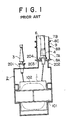
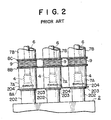
- Fig. 1 is a sectional view illustrating a conventional three-phase transformer as an example of an electrical apparatus used in a power plant or the like, in which 1 is a transformer main body which comprises an iron core 101 and a winding 102. 2 is a tank for containing the transformer main body 1 therein and is filled with an electrically insulating oil. Fig. 2 is a front view of the upper portion of the tank 2, which is a view of the transformer shown in Fig. 1 as viewd from the right in the figure.
- 201 and 202 are high-voltage bushing mounting seats and low-voltage bushing mounting seats formed on the tank 2, respectively, and 3 are high-voltage bushings mounted to the high-voltage bushing mounting seats 201 and is connected to a high-voltage side of the winding 102.
- 203 are bus conductor outer sheath mounting flanges formed in the low-voltage mounting seats 202
- 204 are low-voltage bushing mounting flanges formed in the bus conductor outer sheath mounting flanges 203
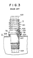
- 4 are low-voltage bushings mounted to low-voltage bushing mounting flanges 204 and are connected to the low-voltage side of the winding 102, the detail of which is shown in Fig. 3.
- 401 is an insulator tube
- 402 is a circular rod-shaped central conductor inserted into the insulator tube 401
- 403 and 404 are an upper terminal and a lower terminal disposed at the opposite ends of the central conductor 402
- 405 is a mounting unit disposed about the outer circumference of the central portion of the insulator tube 401 and secured thereto by cement 406.
- 6 are three-phase separated bus conductors connecting the low-voltage bushings 4 and a generator (not shown)
- 7A are transformer-side three-phase separated bus conductor outer sheaths surrounding the low-voltage bushings 4 at the portion located outside of the tank 2
- 8A and 8B are outer sheath shorting plates in common to three phases and disposed at the opposite ends of the transformer-side three-phase separated bus conductor outer sheaths 7A, one of the shorting plates 8A being mounted to the bus conductor outer sheath mounting flanges 203.
- 7B are generator-side three-phase separated bus conductor outer sheaths surrounding the three-phase separated bus conductors 6, 8C is an outer sheath shorting plate in common to three phases and disposed at one ends of the generator-side three-phase separated bus conductor outer sheaths 7B, a similar outer sheath shorting plate (not shown) being provided at the other ends.
- 9 are expansion joints made of an electrically insulating material and disposed between the transformer-side and the generator-side three-phase separated outer sheaths 7A and 7B.
- the so-called mini-flux structure is adapted, in which a three-phase closed circuit is formed by the three-phase separated bus conductor outer sheaths 7B on the generator-side, the outer sheath shorting plate 8C on one ends of the outer sheaths and the unillustrated outer sheath shorting plate on the other ends of the outer sheaths so that the magnetic flux crosses the closed circuit and generates a current flowing in the direction opposite to the three-phase separated bus conductors 6 thereby generating a magnetic flux which offsets the magnetic flux generated by the current flowing through the three-phase separated bus conductors 6.
- the transformer-side three-phase separated bus conductor outer sheaths 7A and the shorting plates 8A and 8B form a three-phase closed circuit in the mini-flux structure.
- the expansion joint 9 absorbs the dimentional difference between both of the three-phase separated bus conductor outer sheaths 7A and 7B, and an insulating material is selected for the joint to electrically isolate the generator side and the transformer side so that they do not electrically influence each other.
- the conventional electrical apparatus is constructed as above described and the mini-flux structure by the phase separated bus conductors and the outer sheath shorting plates is employed at the outside of the tank, the magnetic fluxes generated by the current flowing through the phase separated bus conductors are cancelled out.
- the mini-flux structure is not adapted at the inside of the tank, a massive magnetic flux is generated by the current flowing through the bushings to increase the stray loss and overheats the adjacent structural members, the tank and the like.
- one object of the present invention is to provide an electrical apparatus free from the above problem of the conventional design.
- Another object of the present invention is to provide an electrical apparatus in which the stray loss is small.
- a further object of the present invention is to provide an electrical apparatus in which the structures around the bushing are not overheated.
- the electrical apparatus of the present invention comprises an enclosure member surrounding each bushing at portion located inside of a tank and connectable to phase-separated bus conductor outer sheaths, and the enclosure members are connected to each other by an enclosure member shorting plate.
- each of the bushings is surrounded at the portion located inside of the tank by an enclosure member, and these enclosure members are connected to phase-separated bus conductor outer sheaths at the outside of the tank, and the enclosure members each is connected by an enclosure member shorting plate, surrounding each of said bushings at the portion located outside of said tank and coaxially surrounding each of said bushings at the portion located inside of said tank, and the enclosure members are connected by an enclosure member shorting plate, thereby to cause the mini-flux structure to extend from the outside to the inside of the tank, whereby the magnetic flux inside of the tank due to the currents flowing through the bushings is cancelled out by the magnetic flux due to the current flowing through the enclosure member.
- Fig. 4 is a sectional view showing a three-phase transformer as an electrical apparatus according to one embodiment of the present invention, in which the transformer main body 1, the iron core 101, the winding 102, the tank 2, the high-voltage bushing mounting seats 201, the high-voltage bushings 3, the three-phase separated bus conductors 6, the generator-side three-phase separated bus conductor outer sheaths 7B, the outer sheath shorting plates 8B and 8C, and the expansion joint 9 are similar to those of the conventional design shown in Fig. 1, so that their explanation will be omitted.
- Fig. 5 is a front view of the upper portion of the tank 2 as viewed the transformer shown in Fig. 4 from the right in the figure.
- 202 is a low-voltage bushing mounting seat formed on the tank 2 and is common for three phases.
- 204 are low-voltage bushing mounting flanges formed on an upper plate 205 of the low-voltage bushing mounting seat 202, 4 are low-voltage bushings mounted to the low-voltage bushing mounting flanges 204 which are connected to the low voltage side of the winding 102.
- FIG. 6 is a front view of the low-voltage bushing and the enclosure member, in which the insulator tube 401, the central conductor 402, the upper and the lower terminals 403 and 404 are similar to those of the conventional design shown in Fig. 3, so that their explanation will be omitted.
- 11 is an enclosure member also serving as a mounting unit and is disposed at the outer circumference of the insulator tube 401 and is secured to the insulator tube by a cemenet 406.
- 111 is a flange, which mounts, by attaching this to the low-voltage bushing mounting flange 204 by the bolts 5A, the low-voltage bushing 4 is mounted in a manner in which the bushing extends through the low-voltage bushing mounting flange 204.
- the 112 is a cylinder member having a general configuration of a circular cylinder, the bottom end [in the figure] of the member has a square cross section of which one side has a length equal to the diameter of the above-mentioned cylinder.
- This cylinder member 112 coaxially surrounds the low-voltage bushing 4 at its portion located inside of the tank 2.
- the flange 111 and the cylinder member 112 are made of a material having a good electrical conductivity such as copper or aluminium, these two constituting an enclosure member 11.
- FIG. 12 illustrates in a perspective view the enclosure member shorting plate 12 and the connecting conductors 13.
- the enclosure member shorting plate 12 has formed therein three circular holes 121 at a pitch equal to the mounting pitch of the low-voltage bushings 4 so that the connecting conductors from the low-voltage bushings 4 to the winding 102 may extend therethrough.
- Figs. 4, 5 and 6, 7A are transformer-side three-phase separated bus conductor outer sheaths surrounding the low-voltage bushings 4 at the portion located outside of the tank 2 and attached to the flange portion 111 of the enclosure members 11 by bolts 50.
- the generator-side has the mini-flux structure constructed by the generator-side three-phase separated bus conductor outer sheaths 7B and the outer sheath shorting plate 8C similarly to the conventional example shown in Fig. 2 to cancel out the magnetic flux.
- a three-phase closed circuit extending into the inside of the tank 2 is formed by the transformer-side three-phase separated bus conductor outer sheaths 7A, the flange portion 111 and the cylindrical portion 112 of the enclosure members 11, the connecting conductors 13, the enclosure member shorting plate 12, and the outer sheath shorting plate 8B outside of the tank 2.
- the enclosure members 11, the enclosure member shorting plate 12 and the connecting conductor 13 are made of copper or aluminium, and in this embodiment these elements are immersed within the insulation oil and cooled, so that these elements are not overheated even when a large current flows therethrough.
- the length of the cylindrical portion 112 of the enclosure members 11 and the position of the enclosure member shorting plate 12 since the area in which the magnetic flux offset effect of these members extends become larger when these elements are extended downwardly in the figure, it is preferable that they extend to the position lower than the low- voltage bushing mounting flanges 204 as well as the upper plate 205 of the low-voltage bushing mounting seat 202 which can be easily overheated because they are close to the low-voltage bushings 4.
- the enclosure members 11 are indirectly connected to each other by the enclosure member shorting plate 12 through the connecting conductors 13 in the above-described embodiment, the enclosure members 11 may be directly connected to each other by the enclosure member shorting plate 12. Also, while a three-phase example has been shown, similar advantageous results can be obtained in case of a single phase.
- each of the bushings is surrounded at the portion located inside of the tank by an enclosure member, and these enclosure members are connected to phase-separated bus conductor outer sheaths at the outside of the tank, and the enclosure members each is connected by an enclosure member shorting plate, so that the arrangement is such that the mini-flux structure extends to the inside of the tank, whereby the magnetic flux inside of the tank due to the currents flowing through the bushings is cancelled out by the magnetic flux due to the current flowing through the enclosure member, resulting in advantageous results that the stray loss is small and the structures around the bushing are not overheated.
Landscapes
- Engineering & Computer Science (AREA)
- Power Engineering (AREA)
- Housings And Mounting Of Transformers (AREA)
- Regulation Of General Use Transformers (AREA)
Applications Claiming Priority (2)
| Application Number | Priority Date | Filing Date | Title |
|---|---|---|---|
| JP154107/88 | 1988-06-21 | ||
| JP63154107A JPH0744116B2 (ja) | 1988-06-21 | 1988-06-21 | 電気機器 |
Publications (3)
| Publication Number | Publication Date |
|---|---|
| EP0348131A2 true EP0348131A2 (de) | 1989-12-27 |
| EP0348131A3 EP0348131A3 (en) | 1990-08-22 |
| EP0348131B1 EP0348131B1 (de) | 1994-06-01 |
Family
ID=15577077
Family Applications (1)
| Application Number | Title | Priority Date | Filing Date |
|---|---|---|---|
| EP89306186A Expired - Lifetime EP0348131B1 (de) | 1988-06-21 | 1989-06-19 | Elektrische Vorrichtung |
Country Status (6)
| Country | Link |
|---|---|
| US (1) | US4980515A (de) |
| EP (1) | EP0348131B1 (de) |
| JP (1) | JPH0744116B2 (de) |
| CA (1) | CA1334855C (de) |
| DE (1) | DE68915620T2 (de) |
| PT (1) | PT90921B (de) |
Cited By (3)
| Publication number | Priority date | Publication date | Assignee | Title |
|---|---|---|---|---|
| US5808536A (en) * | 1996-06-28 | 1998-09-15 | General Signal Corporation | Power transformer and coupling means therefor |
| EP0918341A3 (de) * | 1997-11-19 | 2000-08-02 | ABB Trasformatori S.p.A. | Elektrischer Transformator für hohe und sehr hohe Stromstärken, insbesondere für Öfen und Gleichrichter |
| WO2016004293A1 (en) * | 2014-07-03 | 2016-01-07 | Hubbell Corporation | Transformer security enclosure |
Families Citing this family (6)
| Publication number | Priority date | Publication date | Assignee | Title |
|---|---|---|---|---|
| US6346677B1 (en) | 1999-09-08 | 2002-02-12 | Electro Composites, Inc. | High-voltage bushing provided with external shields |
| US6515232B2 (en) * | 2000-12-15 | 2003-02-04 | Mechanical Dynamics & Analysis, Llc. | High voltage bushing and method of assembling same |
| DE102008013416A1 (de) * | 2008-03-10 | 2009-10-15 | Siemens Aktiengesellschaft | Anordnung mit einem Generator und einem Transformator |
| EP2556521B1 (de) | 2010-04-07 | 2018-05-30 | ABB Schweiz AG | Freiluft trockentransformator |
| US10366824B2 (en) * | 2017-04-11 | 2019-07-30 | Trench Limited | Direct mounting bracket |
| EP3618086B1 (de) | 2018-08-30 | 2021-04-28 | ABB Power Grids Switzerland AG | Abschirmung für einen anschluss einer elektrischen hochspannungsvorrichtung und verfahren zum betrieb davon |
Family Cites Families (7)
| Publication number | Priority date | Publication date | Assignee | Title |
|---|---|---|---|---|
| CA592759A (en) * | 1960-02-16 | P. Tootill William | Support structure for electric conductors | |
| GB416564A (en) * | 1932-12-17 | 1934-09-17 | Gen Electric | Improvements in and relating to the prevention of eddy-current losses in electric switches or circuit breakers and other enclosed electric apparatus |
| DE1540113A1 (de) * | 1965-11-03 | 1969-12-11 | Licentia Gmbh | Anordnung zur Verringerung von Verlusten in der Naehe von Wechselstromdurchfuehrungen |
| JPS5279227A (en) * | 1975-12-26 | 1977-07-04 | Hitachi Ltd | Magnetic shielding equipment for induction apparatus |
| JPS596491B2 (ja) * | 1977-06-01 | 1984-02-13 | 株式会社日立製作所 | 変圧器のリ−ド線引出し装置 |
| JPS549721A (en) * | 1977-06-24 | 1979-01-24 | Hitachi Ltd | Drawing out lead-in wires for electric apparatus |
| US4370512A (en) * | 1981-02-23 | 1983-01-25 | Westinghouse Electric Corp. | Shielding device for electrical inductive structure |
-
1988
- 1988-06-21 JP JP63154107A patent/JPH0744116B2/ja not_active Expired - Lifetime
-
1989
- 1989-06-19 CA CA000603147A patent/CA1334855C/en not_active Expired - Fee Related
- 1989-06-19 EP EP89306186A patent/EP0348131B1/de not_active Expired - Lifetime
- 1989-06-19 DE DE68915620T patent/DE68915620T2/de not_active Expired - Fee Related
- 1989-06-20 US US07/369,039 patent/US4980515A/en not_active Expired - Fee Related
- 1989-06-20 PT PT90921A patent/PT90921B/pt not_active IP Right Cessation
Cited By (4)
| Publication number | Priority date | Publication date | Assignee | Title |
|---|---|---|---|---|
| US5808536A (en) * | 1996-06-28 | 1998-09-15 | General Signal Corporation | Power transformer and coupling means therefor |
| EP0918341A3 (de) * | 1997-11-19 | 2000-08-02 | ABB Trasformatori S.p.A. | Elektrischer Transformator für hohe und sehr hohe Stromstärken, insbesondere für Öfen und Gleichrichter |
| WO2016004293A1 (en) * | 2014-07-03 | 2016-01-07 | Hubbell Corporation | Transformer security enclosure |
| US9812241B2 (en) | 2014-07-03 | 2017-11-07 | Hubbell Incorporated | Transformer security enclosure |
Also Published As
| Publication number | Publication date |
|---|---|
| EP0348131B1 (de) | 1994-06-01 |
| CA1334855C (en) | 1995-03-21 |
| US4980515A (en) | 1990-12-25 |
| EP0348131A3 (en) | 1990-08-22 |
| DE68915620T2 (de) | 1995-01-12 |
| PT90921B (pt) | 1995-06-30 |
| JPH0744116B2 (ja) | 1995-05-15 |
| DE68915620D1 (de) | 1994-07-07 |
| JPH01319918A (ja) | 1989-12-26 |
| PT90921A (pt) | 1989-12-29 |
Similar Documents
| Publication | Publication Date | Title |
|---|---|---|
| EP0348131B1 (de) | Elektrische Vorrichtung | |
| US4140934A (en) | Power terminal structure for stator component of high-output turbo-generator | |
| US6624360B2 (en) | Outdoor high-voltage bushing, and a high voltage switching device having such a bushing | |
| US4370512A (en) | Shielding device for electrical inductive structure | |
| US3621426A (en) | Transformer with bushing compartment | |
| JPH0158725B2 (de) | ||
| JP3982973B2 (ja) | 変流器 | |
| US4345804A (en) | Flexible bushing connector | |
| EP0068158B1 (de) | Elektrischer Transformator | |
| JP2000150249A (ja) | 変圧器用ブッシュ | |
| CN219370888U (zh) | 套管式一体化组合器件 | |
| US3835429A (en) | Current transformer | |
| CN111952059B (zh) | 变压器及变压器系统 | |
| SU1206846A1 (ru) | Устройство дл снижени потерь | |
| JPS61141112A (ja) | 中性点接地リアクトル装置 | |
| JPH0731302Y2 (ja) | 無効電力補償装置における無効電力発生部の構造 | |
| JPS596491B2 (ja) | 変圧器のリ−ド線引出し装置 | |
| JPH023365B2 (de) | ||
| RU2247438C2 (ru) | Трансформатор тока высокого напряжения | |
| US3541231A (en) | Electrical terminal providing a plurality of circuits | |
| JPS6226969Y2 (de) | ||
| JPS5815339U (ja) | ガス絶縁電気機器 | |
| JPS6245467Y2 (de) | ||
| JP2023037465A (ja) | 変流器 | |
| RU1830551C (ru) | Силовой трансформатор высокого напр жени |
Legal Events
| Date | Code | Title | Description |
|---|---|---|---|
| PUAI | Public reference made under article 153(3) epc to a published international application that has entered the european phase |
Free format text: ORIGINAL CODE: 0009012 |
|
| AK | Designated contracting states |
Kind code of ref document: A2 Designated state(s): DE FR GB SE |
|
| PUAL | Search report despatched |
Free format text: ORIGINAL CODE: 0009013 |
|
| AK | Designated contracting states |
Kind code of ref document: A3 Designated state(s): DE FR GB SE |
|
| 17P | Request for examination filed |
Effective date: 19901210 |
|
| 17Q | First examination report despatched |
Effective date: 19920812 |
|
| GRAA | (expected) grant |
Free format text: ORIGINAL CODE: 0009210 |
|
| AK | Designated contracting states |
Kind code of ref document: B1 Designated state(s): DE FR GB SE |
|
| PGFP | Annual fee paid to national office [announced via postgrant information from national office to epo] |
Ref country code: GB Payment date: 19940613 Year of fee payment: 6 |
|
| PGFP | Annual fee paid to national office [announced via postgrant information from national office to epo] |
Ref country code: SE Payment date: 19940615 Year of fee payment: 6 |
|
| PGFP | Annual fee paid to national office [announced via postgrant information from national office to epo] |
Ref country code: DE Payment date: 19940622 Year of fee payment: 6 |
|
| PGFP | Annual fee paid to national office [announced via postgrant information from national office to epo] |
Ref country code: FR Payment date: 19940624 Year of fee payment: 6 |
|
| REF | Corresponds to: |
Ref document number: 68915620 Country of ref document: DE Date of ref document: 19940707 |
|
| REG | Reference to a national code |
Ref country code: GB Ref legal event code: 727 |
|
| REG | Reference to a national code |
Ref country code: GB Ref legal event code: 727A |
|
| ET | Fr: translation filed | ||
| REG | Reference to a national code |
Ref country code: GB Ref legal event code: 727B |
|
| EAL | Se: european patent in force in sweden |
Ref document number: 89306186.1 |
|
| REG | Reference to a national code |
Ref country code: GB Ref legal event code: SP |
|
| PLBE | No opposition filed within time limit |
Free format text: ORIGINAL CODE: 0009261 |
|
| STAA | Information on the status of an ep patent application or granted ep patent |
Free format text: STATUS: NO OPPOSITION FILED WITHIN TIME LIMIT |
|
| 26N | No opposition filed | ||
| PG25 | Lapsed in a contracting state [announced via postgrant information from national office to epo] |
Ref country code: GB Effective date: 19950619 |
|
| PG25 | Lapsed in a contracting state [announced via postgrant information from national office to epo] |
Ref country code: SE Effective date: 19950620 |
|
| GBPC | Gb: european patent ceased through non-payment of renewal fee |
Effective date: 19950619 |
|
| PG25 | Lapsed in a contracting state [announced via postgrant information from national office to epo] |
Ref country code: FR Effective date: 19960229 |
|
| PG25 | Lapsed in a contracting state [announced via postgrant information from national office to epo] |
Ref country code: DE Effective date: 19960301 |
|
| EUG | Se: european patent has lapsed |
Ref document number: 89306186.1 |
|
| REG | Reference to a national code |
Ref country code: FR Ref legal event code: ST |